User Manual
Page 1
... version of this manual. TURBO HD H1T Series Bullet Camera User Manual User Manual Thank you for purchasing our product. If there are any questions, or requests, do not hesitate to change without notice. The updates will readily improve or update the products or procedures described in the manual. 0300001070703 This manual applies to the models below: Type Type I Camera Type II Camera Model DS-2CE16H1T-IT(E) DS-2CE16H1T-IT1(E) DS-2CE16H1T-IT3(E) DS-2CE16H1T-IT5...
... version of this manual. TURBO HD H1T Series Bullet Camera User Manual User Manual Thank you for purchasing our product. If there are any questions, or requests, do not hesitate to change without notice. The updates will readily improve or update the products or procedures described in the manual. 0300001070703 This manual applies to the models below: Type Type I Camera Type II Camera Model DS-2CE16H1T-IT(E) DS-2CE16H1T-IT1(E) DS-2CE16H1T-IT3(E) DS-2CE16H1T-IT5...

User Manual
Page 2
...Operation is likely to cause harmful interference in which case the user will be required to take attention that changes or modification not expressly approved by the party responsible for a Class A digital device, pursuant to part...received, including interference that cannot be disposed of the FCC Rules. The battery is marked with this product to operate the equipment. Regulatory Information FCC Information Please take adequate measures. This equipment generates, uses, and can radiate radio frequency energy and, if not installed and used...documentation for specific battery ...
...Operation is likely to cause harmful interference in which case the user will be required to take attention that changes or modification not expressly approved by the party responsible for a Class A digital device, pursuant to part...received, including interference that cannot be disposed of the FCC Rules. The battery is marked with this product to operate the equipment. Regulatory Information FCC Information Please take adequate measures. This equipment generates, uses, and can radiate radio frequency energy and, if not installed and used...documentation for specific battery ...
User Manual
Page 3
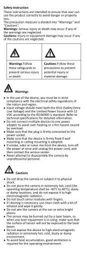
...wall mounting or ceiling mounting is adopted. If smoke, odor or noise rise from the device, turn off the power at the sun or extra bright places. The sensor may be burned out by a laser beam, so when any of the cautions are neglected. Refer to technical specifications for the operating... aim the camera at once and unplug the power cord, and then contact the service center. Never attempt to disassemble the camera by overload. Make sure that the plug is firmly connected to the power socket. Make sure that user can use clean cloth ...
...wall mounting or ceiling mounting is adopted. If smoke, odor or noise rise from the device, turn off the power at the sun or extra bright places. The sensor may be burned out by a laser beam, so when any of the cautions are neglected. Refer to technical specifications for the operating... aim the camera at once and unplug the power cord, and then contact the service center. Never attempt to disassemble the camera by overload. Make sure that the plug is firmly connected to the power socket. Make sure that user can use clean cloth ...
User Manual
Page 4
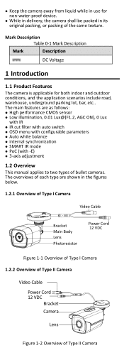
..., 0.01 Lux@(F1.2, AGC ON), 0 Lux with IR IR cut filter with auto switch OSD menu with configurable parameters Auto white balance internal synchronization SMART IR mode PoC (with -E) 3-axis adjustment 1.2 Overview This manual applies to two types of bullet cameras. Mark Description Table 0-1 Mark Description Mark Description DC Voltage 1 Introduction 1.1 Product Features...
..., 0.01 Lux@(F1.2, AGC ON), 0 Lux with IR IR cut filter with auto switch OSD menu with configurable parameters Auto white balance internal synchronization SMART IR mode PoC (with -E) 3-axis adjustment 1.2 Overview This manual applies to two types of bullet cameras. Mark Description Table 0-1 Mark Description Mark Description DC Voltage 1 Introduction 1.1 Product Features...
User Manual
Page 5
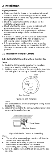
... related equipment is power-off during the installation. Check the specification of the products for repair or maintenance by yourself. 2.1 Installation of the camera and the bracket. If the wall is wooden, use self-tapping screws to secure the camera. If the product does not function properly, contact your dealer or the nearest service center. Screw Hole Cable Hole Template...
... related equipment is power-off during the installation. Check the specification of the products for repair or maintenance by yourself. 2.1 Installation of the camera and the bracket. If the wall is wooden, use self-tapping screws to secure the camera. If the product does not function properly, contact your dealer or the nearest service center. Screw Hole Cable Hole Template...

User Manual
Page 6
Loosen the T screw to adjust the tilt position [0° to check whether the image on the Junction box' cover. 4. Tighten the screw after completing the adjustment. 2.1.2 Ceiling/Wall Mounting with those on the monitor is gotten from the optimum angle. Figure 2-4 Drill Template of the drill template. Power on the ceiling/wall. Loosen the R screw and rotate the camera [0°to 180...
Loosen the T screw to adjust the tilt position [0° to check whether the image on the Junction box' cover. 4. Tighten the screw after completing the adjustment. 2.1.2 Ceiling/Wall Mounting with those on the monitor is gotten from the optimum angle. Figure 2-4 Drill Template of the drill template. Power on the ceiling/wall. Loosen the R screw and rotate the camera [0°to 180...
User Manual
Page 7
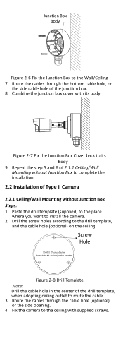
... Cover back to its body. Fix the camera to install the camera. 2. Combine the junction box cover with supplied screws. Route the cables through the cable hole (optional) or the side opening. 4. Paste the drill template (supplied) to the place where you want to the..., and the cable hole (optional) on the ceiling. Repeat the step 5 and 6 of 2.1.1 Ceiling/Wall Mounting without Junction Box to the Wall/Ceiling 7. Junction Box Body Figure 2-6 Fix the Junction Box to complete the installation. 2.2 Installation of Type II Camera 2.2.1 Ceiling/Wall Mounting without Junction Box...
... Cover back to its body. Fix the camera to install the camera. 2. Combine the junction box cover with supplied screws. Route the cables through the cable hole (optional) or the side opening. 4. Paste the drill template (supplied) to the place where you want to the..., and the cable hole (optional) on the ceiling. Repeat the step 5 and 6 of 2.1.1 Ceiling/Wall Mounting without Junction Box to the Wall/Ceiling 7. Junction Box Body Figure 2-6 Fix the Junction Box to complete the installation. 2.2 Installation of Type II Camera 2.2.1 Ceiling/Wall Mounting without Junction Box...

User Manual
Page 8
... No.3 adjusting screw. 2.2.2 Ceiling/Wall Mounting with supplied screws on the Junction box's cover. 4. Steps: 1. Connect the corresponding power cord, and video cable. 6. Tighten the No.1 adjusting screw. 2). Loosen the No.3 adjusting screw to adjust the rotation position [0°to adjust the tilting position [0°to180°]. Tighten the No. 2 adjusting screw. 3). Loosen the No.1 adjusting screw to adjust the pan position [0°to route the cable. 3. Note: Drill the cable hole...
... No.3 adjusting screw. 2.2.2 Ceiling/Wall Mounting with supplied screws on the Junction box's cover. 4. Steps: 1. Connect the corresponding power cord, and video cable. 6. Tighten the No.1 adjusting screw. 2). Loosen the No.3 adjusting screw to adjust the rotation position [0°to adjust the tilting position [0°to180°]. Tighten the No. 2 adjusting screw. 3). Loosen the No.1 adjusting screw to adjust the pan position [0°to route the cable. 3. Note: Drill the cable hole...
User Manual
Page 9
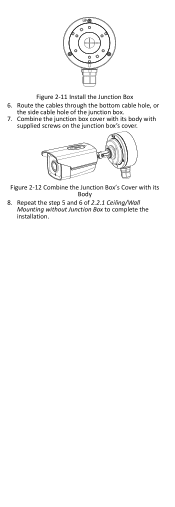
Route the cables through the bottom cable hole, or the side cable hole of 2.2.1 Ceiling/Wall Mounting without Junction Box to complete the installation. Repeat the step 5 and 6 of the junction box. 7. Combine the junction box cover with its body with its Body 8. Figure 2-11 Install the Junction Box 6. Figure 2-12 Combine the Junction Box's Cover with supplied screws on the junction box's cover.
Route the cables through the bottom cable hole, or the side cable hole of 2.2.1 Ceiling/Wall Mounting without Junction Box to complete the installation. Repeat the step 5 and 6 of the junction box. 7. Combine the junction box cover with its body with its Body 8. Figure 2-11 Install the Junction Box 6. Figure 2-12 Combine the Junction Box's Cover with supplied screws on the junction box's cover.
User Manual
Page 10
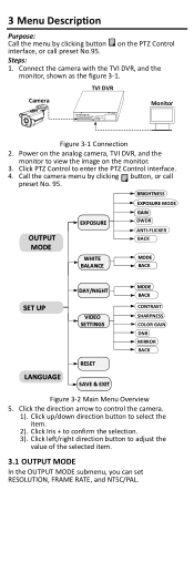
... MODE OUTPUT MODE EXPOSURE GAIN DWDR ANTI-FLICKER BACK WHITE BALANCE MODE BACK SET UP DAY/NIGHT VIDEO SETTINGS MODE BACK CONTRAST SHARPNESS COLOR GAIN DNR MIRROR BACK LANGUAGE RESET SAVE & EXIT Figure 3-2 Main Menu Overview 5. Call the camera menu by clicking button on the PTZ Control interface, or call preset No. 95. Click Iris + to view the image on the analog camera, TVI DVR, and the monitor to confirm the selection. 3). Power on the monitor...
... MODE OUTPUT MODE EXPOSURE GAIN DWDR ANTI-FLICKER BACK WHITE BALANCE MODE BACK SET UP DAY/NIGHT VIDEO SETTINGS MODE BACK CONTRAST SHARPNESS COLOR GAIN DNR MIRROR BACK LANGUAGE RESET SAVE & EXIT Figure 3-2 Main Menu Overview 5. Call the camera menu by clicking button on the PTZ Control interface, or call preset No. 95. Click Iris + to view the image on the analog camera, TVI DVR, and the monitor to confirm the selection. 3). Power on the monitor...
User Manual
Page 11
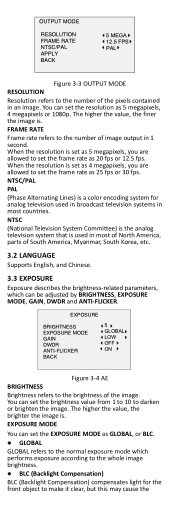
.... EXPOSURE MODE You can be adjusted by BRIGHTNESS, EXPOSURE MODE, GAIN, DWDR and ANTI-FLICKER. OUTPUT MODE RESOLUTION FRAME RATE NTSC/PAL APPLY BACK 5 MEGA 12.5 FPS PAL Figure 3-3 OUTPUT MODE RESOLUTION Resolution refers to the number of image output in 1 second. NTSC (National Television System Committee) is the analog television system that is a color encoding system for the front object to set as 4 megapixels...
.... EXPOSURE MODE You can be adjusted by BRIGHTNESS, EXPOSURE MODE, GAIN, DWDR and ANTI-FLICKER. OUTPUT MODE RESOLUTION FRAME RATE NTSC/PAL APPLY BACK 5 MEGA 12.5 FPS PAL Figure 3-3 OUTPUT MODE RESOLUTION Resolution refers to the number of image output in 1 second. NTSC (National Television System Committee) is the analog television system that is a color encoding system for the front object to set as 4 megapixels...
User Manual
Page 12
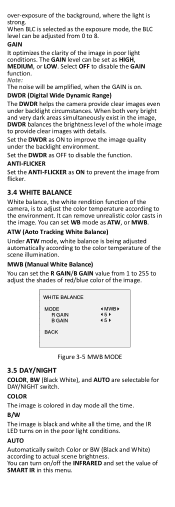
..., where the light is colored in day mode all the time, and the IR LED turns on in the poor light conditions. When BLC is selected as ATW, or MWB. Set the DWDR as ON to 8. You can remove unrealistic color casts in the image. WHITE BALANCE MODE R GAIN B GAIN BACK MWB 5 5 Figure 3-5 MWB MODE 3.5 DAY/NIGHT COLOR, BW (Black White), and AUTO are selectable for DAY/NIGHT switch.
..., where the light is colored in day mode all the time, and the IR LED turns on in the poor light conditions. When BLC is selected as ATW, or MWB. Set the DWDR as ON to 8. You can remove unrealistic color casts in the image. WHITE BALANCE MODE R GAIN B GAIN BACK MWB 5 5 Figure 3-5 MWB MODE 3.5 DAY/NIGHT COLOR, BW (Black White), and AUTO are selectable for DAY/NIGHT switch.
User Manual
Page 13
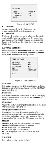
... determines the amount of the color. DNR (Digital Noise Reduction) The DNR function can turn on/off the IR LED to meet the requirements of an image. DAY/NIGHT MODE INFRARED SMART IR BACK AUTO ON 1 Figure 3-6 DAY NIGHT INFRARED You can decrease the noise effect, especially when capturing moving images in color and light between parts of different circumstances. SMART...
... determines the amount of the color. DNR (Digital Noise Reduction) The DNR function can turn on/off the IR LED to meet the requirements of an image. DAY/NIGHT MODE INFRARED SMART IR BACK AUTO ON 1 Figure 3-6 DAY NIGHT INFRARED You can decrease the noise effect, especially when capturing moving images in color and light between parts of different circumstances. SMART...

User Manual
Page 14
3.8 SAVE & EXIT Move the cursor to SAVE & EXIT and click Iris+ to save the setting and exit the menu. UD05378B-A
3.8 SAVE & EXIT Move the cursor to SAVE & EXIT and click Iris+ to save the setting and exit the menu. UD05378B-A
Data Sheet
Page 1
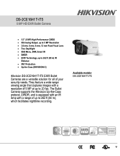
The Bullet Camera supports the Hikvision Up-the-Coax protocol, DWDR, and is equipped with an IR lamp with a resolution of your security needs. Available models: DS-2CE16H1T-IT5 They feature a wide range viewing angle that captures images with a range of up to 262 ft (80 m) IR Distance • IP67 Protection • Up-the-Coax (HIKVISION-C) Hikvision DS-2CE16H1T-IT5 EXIR Bullet Cameras are a versatile solution for all of...
The Bullet Camera supports the Hikvision Up-the-Coax protocol, DWDR, and is equipped with an IR lamp with a resolution of your security needs. Available models: DS-2CE16H1T-IT5 They feature a wide range viewing angle that captures images with a range of up to 262 ft (80 m) IR Distance • IP67 Protection • Up-the-Coax (HIKVISION-C) Hikvision DS-2CE16H1T-IT5 EXIR Bullet Cameras are a versatile solution for all of...
Data Sheet
Page 2
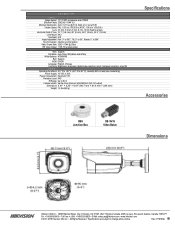
... HD Video Output 1 HD-TVI analog output Menu AGC Support D/N Mode Auto/Color/ BW (Black and White) White Balance ATW/MWB BLC Support WDR DWDR Language English, Chinese Functions Brightness, sharpness, digital noise reduction, mirror, bad pixel correction, smart IR General Operating Conditions -40° F to 140° F (-40° C to 60° C), Humidity 90% or less (non-condensing) Power Supply 12 VDC ± 30% Power Consumption...
... HD Video Output 1 HD-TVI analog output Menu AGC Support D/N Mode Auto/Color/ BW (Black and White) White Balance ATW/MWB BLC Support WDR DWDR Language English, Chinese Functions Brightness, sharpness, digital noise reduction, mirror, bad pixel correction, smart IR General Operating Conditions -40° F to 140° F (-40° C to 60° C), Humidity 90% or less (non-condensing) Power Supply 12 VDC ± 30% Power Consumption...
