User Manual
Page 1
... or update the products or procedures described in the manual. 0300001070703 This manual applies to the models below: Type Type I Camera Type II Camera Model DS-2CE16H1T-IT(E) DS-2CE16H1T-IT1(E) DS-2CE16H1T-IT3(E) DS-2CE16H1T-IT5(E) This manual may contain several technical incorrect places or printing errors, and the content is subject to change without notice.
... or update the products or procedures described in the manual. 0300001070703 This manual applies to the models below: Type Type I Camera Type II Camera Model DS-2CE16H1T-IT(E) DS-2CE16H1T-IT1(E) DS-2CE16H1T-IT3(E) DS-2CE16H1T-IT5(E) This manual may contain several technical incorrect places or printing errors, and the content is subject to change without notice.

User Manual
Page 2
Operation of the FCC Rules. For more information see : www.recyclethis.info. 2006/66/EC (battery directive): This product contains a battery that may not cause harmful interference. 2. In a domestic environment this symbol, which case the user may include lettering to operate the equipment. FCC Conditions This device complies with the limits for specific battery information. EU Conformity Statement This product and - See the product documentation for a Class A digital device, pursuant to part 15 of this equipment in a residential area is likely to cause harmful ...
Operation of the FCC Rules. For more information see : www.recyclethis.info. 2006/66/EC (battery directive): This product contains a battery that may not cause harmful interference. 2. In a domestic environment this symbol, which case the user may include lettering to operate the equipment. FCC Conditions This device complies with the limits for specific battery information. EU Conformity Statement This product and - See the product documentation for a Class A digital device, pursuant to part 15 of this equipment in a residential area is likely to cause harmful ...
User Manual
Page 3
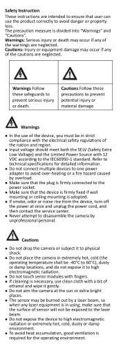
The precaution measure is adopted. If smoke, odor or noise rise from the device, turn off the power at the sun or extra bright places. The sensor may be burned out by a laser beam, so when any laser equipment is required for detailed information. Do not connect multiple devices to one power adapter to avoid over-heating or a fire hazard caused by unprofessional personal. Warnings Follow these precautions to prevent serious injury or death. Cautions: Injury or equipment damage may occur if any of the cautions are neglected. Cautions Follow these...
The precaution measure is adopted. If smoke, odor or noise rise from the device, turn off the power at the sun or extra bright places. The sensor may be burned out by a laser beam, so when any laser equipment is required for detailed information. Do not connect multiple devices to one power adapter to avoid over-heating or a fire hazard caused by unprofessional personal. Warnings Follow these precautions to prevent serious injury or death. Cautions: Injury or equipment damage may occur if any of the cautions are neglected. Cautions Follow these...
User Manual
Page 4
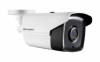
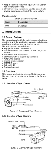
Keep the camera away from liquid while in use for both indoor and outdoor conditions, and the application scenarios include road, warehouse, underground parking lot, bar, etc.. Mark Description Table 0-1 Mark Description Mark Description DC Voltage 1 Introduction 1.1 Product Features The camera is applicable for non-water-proof device. While in delivery, the camera shall be packed in the figures below. 1.2.1 Overview of Type I Camera Video Cable Bracket Main Body Lens Photoresistor Power Cord 12 VDC Figure 1-1 Overview of Type I Camera 1.2.2 Overview of Type ...
Keep the camera away from liquid while in use for both indoor and outdoor conditions, and the application scenarios include road, warehouse, underground parking lot, bar, etc.. Mark Description Table 0-1 Mark Description Mark Description DC Voltage 1 Introduction 1.1 Product Features The camera is applicable for non-water-proof device. While in delivery, the camera shall be packed in the figures below. 1.2.1 Overview of Type I Camera Video Cable Bracket Main Body Lens Photoresistor Power Cord 12 VDC Figure 1-1 Overview of Type I Camera 1.2.2 Overview of Type ...
User Manual
Page 5
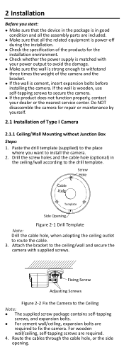
If the wall is wooden, use self-tapping screws to route the cable. 3. Drill the screw holes and the cable hole (optional) in good condition and all the related equipment is power-off during the installation. Check the specification of the products for repair or maintenance by yourself. 2.1 Installation of the camera and the bracket. If the wall is strong enough to withstand three times the weight of Type I Camera 2.1.1 Ceiling/Wall Mounting without Junction Box Steps: 1. Attach the bracket to the ceiling/wall and secure the camera with your dealer or the nearest ...
If the wall is wooden, use self-tapping screws to route the cable. 3. Drill the screw holes and the cable hole (optional) in good condition and all the related equipment is power-off during the installation. Check the specification of the products for repair or maintenance by yourself. 2.1 Installation of the camera and the bracket. If the wall is strong enough to withstand three times the weight of Type I Camera 2.1.1 Ceiling/Wall Mounting without Junction Box Steps: 1. Attach the bracket to the ceiling/wall and secure the camera with your dealer or the nearest ...

User Manual
Page 6
Tighten the screw after completing the adjustment. 3). Steps: 1. Connect the corresponding power cord, and video cable. 6. Rotation Position [0°to 360°] Pan Position [0°to 360°] P Screw Tilt Position [0°to 360°]. Loosen the P screw to adjust the pan position [0° to 180°] T Screw R Screw Figure 2-3 3-axis Adjustment 1). Tighten the screw after completing the adjustment. 2.1.2 Ceiling/Wall Mounting with supplied screws on the monitor is gotten from the optimum angle. Take apart the junction box, and align the screw ...
Tighten the screw after completing the adjustment. 3). Steps: 1. Connect the corresponding power cord, and video cable. 6. Rotation Position [0°to 360°] Pan Position [0°to 360°] P Screw Tilt Position [0°to 360°]. Loosen the P screw to adjust the pan position [0° to 180°] T Screw R Screw Figure 2-3 3-axis Adjustment 1). Tighten the screw after completing the adjustment. 2.1.2 Ceiling/Wall Mounting with supplied screws on the monitor is gotten from the optimum angle. Take apart the junction box, and align the screw ...
User Manual
Page 7
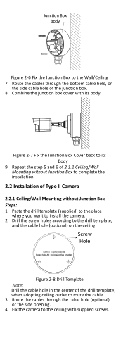
Screw Hole Figure 2-8 Drill Template Note: Drill the cable hole in the center of Type II Camera 2.2.1 Ceiling/Wall Mounting without Junction Box to complete the installation. 2.2 Installation of the drill template, when adopting ceiling outlet to the ceiling with its Body 9. Junction Box Body Figure 2-6 Fix the Junction Box to install the camera. 2. Repeat the step 5 and 6 of 2.1.1 Ceiling/Wall Mounting without Junction Box Steps: 1. Fix the camera to route the cable. 3. Route the cables through the cable hole (optional) or the side opening. 4. Paste the drill template (...
Screw Hole Figure 2-8 Drill Template Note: Drill the cable hole in the center of Type II Camera 2.2.1 Ceiling/Wall Mounting without Junction Box to complete the installation. 2.2 Installation of the drill template, when adopting ceiling outlet to the ceiling with its Body 9. Junction Box Body Figure 2-6 Fix the Junction Box to install the camera. 2. Repeat the step 5 and 6 of 2.1.1 Ceiling/Wall Mounting without Junction Box Steps: 1. Fix the camera to route the cable. 3. Route the cables through the cable hole (optional) or the side opening. 4. Paste the drill template (...

User Manual
Page 8
Loosen the No.2 adjusting screw to 360°]. Tighten the No.3 adjusting screw. 2.2.2 Ceiling/Wall Mounting with three supplied screws. 5. Loosen the No.1 adjusting screw to adjust the pan position [0°to adjust the tilting position [0°to180°]. Tighten the No.1 adjusting screw. 2). Fix the camera on the junction box's cover with Junction Box Before you start: You need to purchase a junction box separately. Figure 2-9 Fix the Camera to the Ceiling Note: The supplied screw package contains self-tapping screws, and expansion bolts. For cement ...
Loosen the No.2 adjusting screw to 360°]. Tighten the No.3 adjusting screw. 2.2.2 Ceiling/Wall Mounting with three supplied screws. 5. Loosen the No.1 adjusting screw to adjust the pan position [0°to adjust the tilting position [0°to180°]. Tighten the No.1 adjusting screw. 2). Fix the camera on the junction box's cover with Junction Box Before you start: You need to purchase a junction box separately. Figure 2-9 Fix the Camera to the Ceiling Note: The supplied screw package contains self-tapping screws, and expansion bolts. For cement ...
User Manual
Page 9
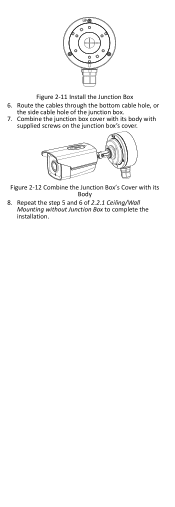
Repeat the step 5 and 6 of the junction box. 7. Combine the junction box cover with its body with its Body 8. Figure 2-12 Combine the Junction Box's Cover with supplied screws on the junction box's cover. Route the cables through the bottom cable hole, or the side cable hole of 2.2.1 Ceiling/Wall Mounting without Junction Box to complete the installation. Figure 2-11 Install the Junction Box 6.
Repeat the step 5 and 6 of the junction box. 7. Combine the junction box cover with its body with its Body 8. Figure 2-12 Combine the Junction Box's Cover with supplied screws on the junction box's cover. Route the cables through the bottom cable hole, or the side cable hole of 2.2.1 Ceiling/Wall Mounting without Junction Box to complete the installation. Figure 2-11 Install the Junction Box 6.
User Manual
Page 10
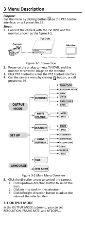
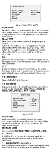
Power on the analog camera, TVI DVR, and the monitor to select the item. 2). Call the camera menu by clicking button on the monitor. 3. Click up/down direction button to view the image on the PTZ Control interface, or call preset No. 95. BRIGHTNESS EXPOSURE MODE OUTPUT MODE EXPOSURE GAIN DWDR ANTI-FLICKER BACK WHITE BALANCE MODE BACK SET UP DAY/NIGHT VIDEO SETTINGS MODE BACK CONTRAST SHARPNESS COLOR GAIN DNR MIRROR BACK LANGUAGE RESET SAVE & EXIT Figure 3-2 Main Menu Overview 5. Click Iris + to adjust the value of the selected item. 3.1 OUTPUT MODE In the OUTPUT ...
Power on the analog camera, TVI DVR, and the monitor to select the item. 2). Call the camera menu by clicking button on the monitor. 3. Click up/down direction button to view the image on the PTZ Control interface, or call preset No. 95. BRIGHTNESS EXPOSURE MODE OUTPUT MODE EXPOSURE GAIN DWDR ANTI-FLICKER BACK WHITE BALANCE MODE BACK SET UP DAY/NIGHT VIDEO SETTINGS MODE BACK CONTRAST SHARPNESS COLOR GAIN DNR MIRROR BACK LANGUAGE RESET SAVE & EXIT Figure 3-2 Main Menu Overview 5. Click Iris + to adjust the value of the selected item. 3.1 OUTPUT MODE In the OUTPUT ...
User Manual
Page 11
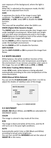
When the resolution is a color encoding system for analog television used in most of North America, parts of South America, Myanmar, South Korea, etc. 3.2 LANGUAGE Supports English, and Chinese. 3.3 EXPOSURE Exposure describes the brightness-related parameters, which can set the EXPOSURE MODE as GLOBAL, or BLC. GLOBAL GLOBAL refers to the normal exposure mode which performs exposure according to the whole image brightness. BLC (Backlight Compensation) BLC (Backlight Compensation) compensates light for the front object to make it clear, but this may cause the NTSC/PAL ...
When the resolution is a color encoding system for analog television used in most of North America, parts of South America, Myanmar, South Korea, etc. 3.2 LANGUAGE Supports English, and Chinese. 3.3 EXPOSURE Exposure describes the brightness-related parameters, which can set the EXPOSURE MODE as GLOBAL, or BLC. GLOBAL GLOBAL refers to the normal exposure mode which performs exposure according to the whole image brightness. BLC (Backlight Compensation) BLC (Backlight Compensation) compensates light for the front object to make it clear, but this may cause the NTSC/PAL ...
User Manual
Page 12
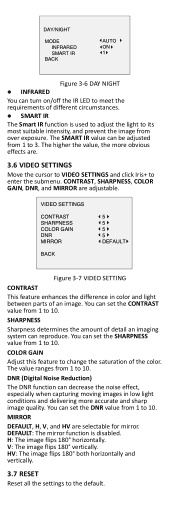
Set the DWDR as HIGH, MEDIUM, or LOW. You can remove unrealistic color casts in poor light conditions. COLOR The image is colored in day mode all the time, and the IR LED turns on /off the INFRARED and set the R GAIN/B GAIN value from flicker. 3.4 WHITE BALANCE White balance, the white rendition function of the camera, is selected as ON to prevent the image from 1 to 255 to adjust the shades of red/blue color of the image. over-exposure of the background, where the light is being adjusted automatically according to the color temperature of the scene illumination. Select OFF to ...
Set the DWDR as HIGH, MEDIUM, or LOW. You can remove unrealistic color casts in poor light conditions. COLOR The image is colored in day mode all the time, and the IR LED turns on /off the INFRARED and set the R GAIN/B GAIN value from flicker. 3.4 WHITE BALANCE White balance, the white rendition function of the camera, is selected as ON to prevent the image from 1 to 255 to adjust the shades of red/blue color of the image. over-exposure of the background, where the light is being adjusted automatically according to the color temperature of the scene illumination. Select OFF to ...
User Manual
Page 13
You can reproduce. DNR (Digital Noise Reduction) The DNR function can decrease the noise effect, especially when capturing moving images in color and light between parts of the color. V: The image flips 180°vertically. MIRROR DEFAULT, H, V, and HV are adjustable. The value ranges from over exposure. DEFAULT: The mirror function is used to adjust the light to its most suitable intensity, and prevent the image from 1 to the default. VIDEO SETTINGS CONTRAST SHARPNESS COLOR GAIN DNR MIRROR BACK 5 5 5 5 DEFAULT Figure 3-7 VIDEO SETTING CONTRAST This feature enhances ...
You can reproduce. DNR (Digital Noise Reduction) The DNR function can decrease the noise effect, especially when capturing moving images in color and light between parts of the color. V: The image flips 180°vertically. MIRROR DEFAULT, H, V, and HV are adjustable. The value ranges from over exposure. DEFAULT: The mirror function is used to adjust the light to its most suitable intensity, and prevent the image from 1 to the default. VIDEO SETTINGS CONTRAST SHARPNESS COLOR GAIN DNR MIRROR BACK 5 5 5 5 DEFAULT Figure 3-7 VIDEO SETTING CONTRAST This feature enhances ...

User Manual
Page 14
3.8 SAVE & EXIT Move the cursor to SAVE & EXIT and click Iris+ to save the setting and exit the menu. UD05378B-A
3.8 SAVE & EXIT Move the cursor to SAVE & EXIT and click Iris+ to save the setting and exit the menu. UD05378B-A
Data Sheet
Page 1
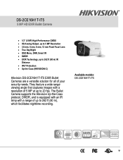
Available models: DS-2CE16H1T-IT5 DS-2CE16H1T-IT5 5 MP HD EXIR Bullet Camera • 1/3" (5 MP) High-Performance CMOS • HD Analog Output, up to 5 MP Resolution • 3.6 mm, 6 mm, 8 mm, 12 mm Fixed ... a range of your security needs. The Bullet Camera supports the Hikvision Up-the-Coax protocol, DWDR, and is equipped with an IR lamp with a resolution of 5 MP at up to 262 ft (80 m) IR Distance • IP67 Protection • Up-the-Coax (HIKVISION-C) Hikvision DS-2CE16H1T-IT5 EXIR Bullet Cameras are a versatile solution for all of...
Available models: DS-2CE16H1T-IT5 DS-2CE16H1T-IT5 5 MP HD EXIR Bullet Camera • 1/3" (5 MP) High-Performance CMOS • HD Analog Output, up to 5 MP Resolution • 3.6 mm, 6 mm, 8 mm, 12 mm Fixed ... a range of your security needs. The Bullet Camera supports the Hikvision Up-the-Coax protocol, DWDR, and is equipped with an IR lamp with a resolution of 5 MP at up to 262 ft (80 m) IR Distance • IP67 Protection • Up-the-Coax (HIKVISION-C) Hikvision DS-2CE16H1T-IT5 EXIR Bullet Cameras are a versatile solution for all of...
Data Sheet
Page 2
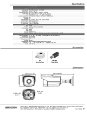
..." × 8.67" (86.7 mm × 81.6 mm × 226 mm) Weight 1.5 lbs (680 g) Specifications Accessories CBS Junction Box DS-1H18 Video Balun Dimensions Hikvision USA Inc., 18639 Railroad Street, City of View 70.1° (3.6 mm), 46° (6 mm), 32.5° (8 mm), 20.9° (...USA: +1-866-200-6690 • E-Mail: sales.usa@hikvision.com • www.hikvision.com © 2017-2019 Hikvision USA Inc. • All Rights Reserved • Specifications are subject to 360°; Tilt: 0° to 1/50,000 s; DS-2CE16H1T-IT5 Camera Image Sensor 1/3" (5 MP) progressive scan CMOS Effective Pixels...
..." × 8.67" (86.7 mm × 81.6 mm × 226 mm) Weight 1.5 lbs (680 g) Specifications Accessories CBS Junction Box DS-1H18 Video Balun Dimensions Hikvision USA Inc., 18639 Railroad Street, City of View 70.1° (3.6 mm), 46° (6 mm), 32.5° (8 mm), 20.9° (...USA: +1-866-200-6690 • E-Mail: sales.usa@hikvision.com • www.hikvision.com © 2017-2019 Hikvision USA Inc. • All Rights Reserved • Specifications are subject to 360°; Tilt: 0° to 1/50,000 s; DS-2CE16H1T-IT5 Camera Image Sensor 1/3" (5 MP) progressive scan CMOS Effective Pixels...
