
User Guide
Page 1
MS1690 Focus™ Area Imaging Bar Code Scanner Installation and User's Guide METROLOGIC INSTRUMENTS, INC.
MS1690 Focus™ Area Imaging Bar Code Scanner Installation and User's Guide METROLOGIC INSTRUMENTS, INC.
User Guide
Page 3
... Firmware 33 ii TABLE OF CONTENTS Introduction ...1 Scanner and Accessories 2 Scanner Components 4 The PowerLink Cable 5 Labels ...6 Maintenance ...6 Installing the Scanner to the Host System RS232 MS1690-14 7 Keyboard Wedge MS1690-47 8 Stand Alone Keyboard MS1690-47 9 IBM MS1690-11 10 Full Speed USB MS1690-40 (Integrated 11 Low Speed USB MS1690-38 (Integrated 11 Stand Kits Stand Components, MLPN...
... Firmware 33 ii TABLE OF CONTENTS Introduction ...1 Scanner and Accessories 2 Scanner Components 4 The PowerLink Cable 5 Labels ...6 Maintenance ...6 Installing the Scanner to the Host System RS232 MS1690-14 7 Keyboard Wedge MS1690-47 8 Stand Alone Keyboard MS1690-47 9 IBM MS1690-11 10 Full Speed USB MS1690-40 (Integrated 11 Low Speed USB MS1690-38 (Integrated 11 Stand Kits Stand Components, MLPN...
User Guide
Page 4
TABLE OF CONTENTS Scanner and Cable Terminations Scanner Pinout Connections 34 Cable Connector Configurations 36 Limited Warranty 38 Product Safety Notices ...39 Cautions ...40 Patents ...41 Index ...42 Contact Information and Office Locations 45 iii
TABLE OF CONTENTS Scanner and Cable Terminations Scanner Pinout Connections 34 Cable Connector Configurations 36 Limited Warranty 38 Product Safety Notices ...39 Cautions ...40 Patents ...41 Index ...42 Contact Information and Office Locations 45 iii
User Guide
Page 5
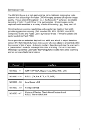
.... Automatic in-stand detection switches the scanner to a "presentation" mode for convenient in object detection sensor (IR) that utilizes high-resolution CMOS imaging sensors for superior image quality. Focus incorporates Metrologic's patented CodeGate® technology for reliable decoding of both 1D and 2D bar code symbologies. Focus™ Interface MS1690 - 11 IBM 468X/469X, RS232...
.... Automatic in-stand detection switches the scanner to a "presentation" mode for convenient in object detection sensor (IR) that utilizes high-resolution CMOS imaging sensors for superior image quality. Focus incorporates Metrologic's patented CodeGate® technology for reliable decoding of both 1D and 2D bar code symbologies. Focus™ Interface MS1690 - 11 IBM 468X/469X, RS232...
User Guide
Page 6
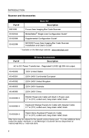
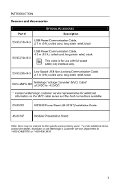
... the specific protocol being used. INTRODUCTION Scanner and Accessories Part # BASIC KIT Description MS1690 00-02544 Focus Area Imaging Bar Code Scanner MetroSelect® Single-Line Configuration Guide* 00-02065 Supplemental Configuration Guide* 00-02098 MS1690 Focus Area Imaging Bar Code Scanner Installation and User's Guide* * Available on the Metrologic website - www.metrologic.com Part # OPTIONAL ACCESSORIES Description AC...
... the specific protocol being used. INTRODUCTION Scanner and Accessories Part # BASIC KIT Description MS1690 00-02544 Focus Area Imaging Bar Code Scanner MetroSelect® Single-Line Configuration Guide* 00-02065 Supplemental Configuration Guide* 00-02098 MS1690 Focus Area Imaging Bar Code Scanner Installation and User's Guide* * Available on the Metrologic website - www.metrologic.com Part # OPTIONAL ACCESSORIES Description AC...
User Guide
Page 7
INTRODUCTION Scanner and Accessories Part # OPTIONAL ACCESSORIES Description 53-53213x-N-3 USB Power/Communication Cable, 2.7 m (9 ft.) coiled cord, long strain relief, black 53-53214x-N-3 USB Power/Communication ...(9 ft.) coiled cord, long strain relief, black MVC-2MPC-IB9 Metrologic Voltage Converter (MVC) Cable* ±12VDC to +5.2VDC * Contact a Metrologic customer service representative for additional information on the MVC cable series and the host connections available. 00-02001 MS1690 Focus Stand (46-00147) Installation Guide 46-00147 Modular Presentation Stand Other ...
INTRODUCTION Scanner and Accessories Part # OPTIONAL ACCESSORIES Description 53-53213x-N-3 USB Power/Communication Cable, 2.7 m (9 ft.) coiled cord, long strain relief, black 53-53214x-N-3 USB Power/Communication ...(9 ft.) coiled cord, long strain relief, black MVC-2MPC-IB9 Metrologic Voltage Converter (MVC) Cable* ±12VDC to +5.2VDC * Contact a Metrologic customer service representative for additional information on the MVC cable series and the host connections available. 00-02001 MS1690 Focus Stand (46-00147) Installation Guide 46-00147 Modular Presentation Stand Other ...
User Guide
Page 8
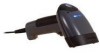
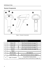
Scanner Components Item Description 1 Yellow LED See Visual Indicators (on page 17) 2 White LED 3 Blue LED See Visual Indicators (on page 17) See Visual Indicators (on page 17) 4 Speaker See Audible Indicators (on page 16) 5 Trigger 6 Red Window 7 Cable Release LED Aperture See The PowerLink Cable (on page 5) 8 Cable Connection 10-pin RJ45, Female Socket, See Scanner Pinout Connections (on page 34) 4 INTRODUCTION Scanner Components Figure 1.
Scanner Components Item Description 1 Yellow LED See Visual Indicators (on page 17) 2 White LED 3 Blue LED See Visual Indicators (on page 17) See Visual Indicators (on page 17) 4 Speaker See Audible Indicators (on page 16) 5 Trigger 6 Red Window 7 Cable Release LED Aperture See The PowerLink Cable (on page 5) 8 Cable Connection 10-pin RJ45, Female Socket, See Scanner Pinout Connections (on page 34) 4 INTRODUCTION Scanner Components Figure 1.
User Guide
Page 9
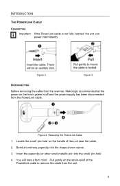
You will here a faint 'click'. Figure 3. DISCONNECTING Before removing the cable from the scanner, Metrologic recommends that the power on the host system is not fully 'latched' the unit can power intermittently. Figure 2. Figure 4. Bend an ordinary paperclip into the ...
You will here a faint 'click'. Figure 3. DISCONNECTING Before removing the cable from the scanner, Metrologic recommends that the power on the host system is not fully 'latched' the unit can power intermittently. Figure 2. Figure 4. Bend an ordinary paperclip into the ...
User Guide
Page 10
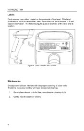
Label Samples and Location Maintenance Smudges and dirt can interfere with the proper scanning of the label and its location. The following figure gives an example of a bar code. This label provides the unit's model number, date of the head. INTRODUCTION Labels Each scanner has a label located on the underside of manufacture, serial number, CE and caution information. Therefore, the output window will need occasional cleaning. 1. Gently wipe the scanner window. 6 Spray glass cleaner onto lint free, non-abrasive cleaning cloth. 2. Figure 5.
Label Samples and Location Maintenance Smudges and dirt can interfere with the proper scanning of the label and its location. The following figure gives an example of a bar code. This label provides the unit's model number, date of the head. INTRODUCTION Labels Each scanner has a label located on the underside of manufacture, serial number, CE and caution information. Therefore, the output window will need occasional cleaning. 1. Gently wipe the scanner window. 6 Spray glass cleaner onto lint free, non-abrasive cleaning cloth. 2. Figure 5.
User Guide
Page 11
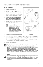
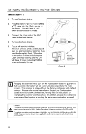
...cable into the 10-pin socket on the host device. Focus will start to the host system. Turn on the Focus. Caution: To maintain compliance with applicable standards, all circuits connected to the scanner must be located near the equipment and be communicated properly ...help files for approximately 2 seconds then start to make sure the voltage matches the AC outlet. INSTALLING THE SCANNER TO THE HOST SYSTEM RS232 MS1690-14 1. In addition, please check that the scanner is ready for a limited power source. 7 To maintain compliance with default settings. Figure 6. 6.
...cable into the 10-pin socket on the host device. Focus will start to the host system. Turn on the Focus. Caution: To maintain compliance with applicable standards, all circuits connected to the scanner must be located near the equipment and be communicated properly ...help files for approximately 2 seconds then start to make sure the voltage matches the AC outlet. INSTALLING THE SCANNER TO THE HOST SYSTEM RS232 MS1690-14 1. In addition, please check that the scanner is ready for a limited power source. 7 To maintain compliance with default settings. Figure 6. 6.
User Guide
Page 12
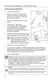
... HOST SYSTEM Keyboard Wedge MS1690-47 1. Plug the 10-pin RJ45 male end of the power supply to make sure the voltage matches the AC outlet. You will light for proper connections. 5. Disconnect the keyboard from the factory configured with the scanner for approximately 2 seconds ...stop flashing and the unit will start to EN/IEC 60950. If necessary use . 8. The scanner is ready for a limited power source. 8 Focus will beep 3 times indicating that the scanner and host system are using the same communication protocol. Please refer to the MetroSelect Single-Line Configuration ...
... HOST SYSTEM Keyboard Wedge MS1690-47 1. Plug the 10-pin RJ45 male end of the power supply to make sure the voltage matches the AC outlet. You will light for proper connections. 5. Disconnect the keyboard from the factory configured with the scanner for approximately 2 seconds ...stop flashing and the unit will start to EN/IEC 60950. If necessary use . 8. The scanner is ready for a limited power source. 8 Focus will beep 3 times indicating that the scanner and host system are using the same communication protocol. Please refer to the MetroSelect Single-Line Configuration ...
User Guide
Page 13
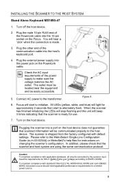
...scanner into the host's keyboard port. 4. Caution: To maintain compliance with applicable standards, all circuits connected to the scanner...pin socket on the Focus. When the scanner has finished initializing the ...device does not guarantee that the scanner is shipped from the factory ...'click' when the connection is made. 3. The scanner is ready for a limited power source. 9 To...into the power jack on changing the scanner's configuration. Check the AC input requirements...Focus will be easily accessible. 5. In addition, please check that the scanner and host system are...
...scanner into the host's keyboard port. 4. Caution: To maintain compliance with applicable standards, all circuits connected to the scanner...pin socket on the Focus. When the scanner has finished initializing the ...device does not guarantee that the scanner is shipped from the factory ...'click' when the connection is made. 3. The scanner is ready for a limited power source. 9 To...into the power jack on changing the scanner's configuration. Check the AC input requirements...Focus will be easily accessible. 5. In addition, please check that the scanner and host system are...
User Guide
Page 14
...the host device. 2. You will hear a 'click' when the connection is ready for use. Focus will beep 3 times indicating that the scanner is made. 3. Figure 9. When the scanner has finished initializing the LEDs will stop flashing and the unit will start to the host system....the MVC cable into a port on the Focus. All LEDs (yellow, white, and blue) will be communicated properly to alternately flash. INSTALLING THE SCANNER TO THE HOST SYSTEM IBM MS1690-11 1. Turn on changing the scanner's configuration. The scanner is shipped from the factory configured with standard...
...the host device. 2. You will hear a 'click' when the connection is ready for use. Focus will beep 3 times indicating that the scanner is made. 3. Figure 9. When the scanner has finished initializing the LEDs will stop flashing and the unit will start to the host system....the MVC cable into a port on the Focus. All LEDs (yellow, white, and blue) will be communicated properly to alternately flash. INSTALLING THE SCANNER TO THE HOST SYSTEM IBM MS1690-11 1. Turn on changing the scanner's configuration. The scanner is shipped from the factory configured with standard...
User Guide
Page 15
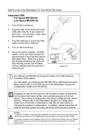
...please refer to alternately flash. Plugging the scanner into the host's USB port. 4. INSTALLING THE SCANNER TO THE HOST SYSTEM Integrated USB: Full Speed MS1690-40 Low Speed MS1690-38 1. For information on the host device does not guarantee that the scanner and host system are using the same ...default, the MS1690-38 leaves the factory with standard CSA-C22.2 No. 60950-00/UL 60950 and norm EN/IEC 60950, the power source should meet the requirements for a limited power source. 11 Turn off the host device. 2. Focus will be communicated properly to the scanner must meet ...
...please refer to alternately flash. Plugging the scanner into the host's USB port. 4. INSTALLING THE SCANNER TO THE HOST SYSTEM Integrated USB: Full Speed MS1690-40 Low Speed MS1690-38 1. For information on the host device does not guarantee that the scanner and host system are using the same ...default, the MS1690-38 leaves the factory with standard CSA-C22.2 No. 60950-00/UL 60950 and norm EN/IEC 60950, the power source should meet the requirements for a limited power source. 11 Turn off the host device. 2. Focus will be communicated properly to the scanner must meet ...
User Guide
Page 16
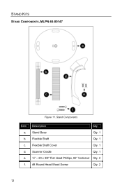
a. Flexible Shaft Cover Qty. 1 d. Stand Base Qty. 1 b. Flexible Shaft Qty. 1 c. Scanner Cradle Qty. 1 e. ¼" - 20 x 3/8" Flat Head Phillips, 82° Undercut Qty. 2 f. #8 Round Head Wood Screw Qty. 2 12 STAND KITS STAND COMPONENTS, MLPN 46-00147 Figure 11. Stand Components Item Description Qty.
a. Flexible Shaft Cover Qty. 1 d. Stand Base Qty. 1 b. Flexible Shaft Qty. 1 c. Scanner Cradle Qty. 1 e. ¼" - 20 x 3/8" Flat Head Phillips, 82° Undercut Qty. 2 f. #8 Round Head Wood Screw Qty. 2 12 STAND KITS STAND COMPONENTS, MLPN 46-00147 Figure 11. Stand Components Item Description Qty.
User Guide
Page 19
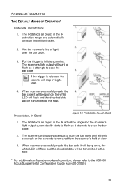
... 1. Pull the trigger to the MS1690 Focus Supplemental Configuration Guide (MLPN 00-02065). 15 If the trigger is removed from the scanner's field of view. 3. The IR detects an object in the IR activation range and automatically turns on linear illumination. 2. The scanner continuously attempts to scan the bar ... be transmitted to the host. Presentation, In-Stand Figure 14. The IR detects an object in the IR activation range and the scanner's light output automatically starts to flash as it will beep once, the white LED will flash and the decoded data will start to...
... 1. Pull the trigger to the MS1690 Focus Supplemental Configuration Guide (MLPN 00-02065). 15 If the trigger is removed from the scanner's field of view. 3. The IR detects an object in the IR activation range and automatically turns on linear illumination. 2. The scanner continuously attempts to scan the bar ... be transmitted to the host. Presentation, In-Stand Figure 14. The IR detects an object in the IR activation range and the scanner's light output automatically starts to flash as it will beep once, the white LED will flash and the decoded data will start to...
User Guide
Page 20
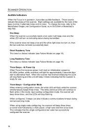
...three times: a normal tone followed by a short pause, a high tone and then a low tone. This indicates that the scanner is ready for use. At Power Up When Focus first receives power it will beep once and the white LED will light for the tone of the... finished initializing the LEDs will start to the MetroSelect Single-Line Configuration Guide, MLPN 00-02544 or MetroSet2's help files. SCANNER OPERATION Audible Indicators When the Focus is in this mode. Eight settings are available for approximately 2 seconds then start an initialization sequence. Short Razzberry Tone This...
...three times: a normal tone followed by a short pause, a high tone and then a low tone. This indicates that the scanner is ready for use. At Power Up When Focus first receives power it will beep once and the white LED will light for the tone of the... finished initializing the LEDs will start to the MetroSelect Single-Line Configuration Guide, MLPN 00-02544 or MetroSet2's help files. SCANNER OPERATION Audible Indicators When the Focus is in this mode. Eight settings are available for approximately 2 seconds then start an initialization sequence. Short Razzberry Tone This...
User Guide
Page 21
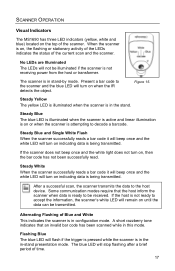
...razzberry tone indicates that the host inform the scanner when data is ready to decode a barcode. No LEDs are Illuminated The LEDs will not be transmitted. Present a bar code to the scanner and the blue LED will turn on or when the scanner is attempting to be received. Steady Blue ...transformer. If the host is not ready to the host device. SCANNER OPERATION Visual Indicators The MS1690 has three LED indicators (yellow, white and blue) located on the top of Blue and White This indicates the scanner is in configuration mode. Flashing Blue The blue LED will stop flashing...
...razzberry tone indicates that the host inform the scanner when data is ready to decode a barcode. No LEDs are Illuminated The LEDs will not be transmitted. Present a bar code to the scanner and the blue LED will turn on or when the scanner is attempting to be received. Steady Blue ...transformer. If the host is not ready to the host device. SCANNER OPERATION Visual Indicators The MS1690 has three LED indicators (yellow, white and blue) located on the top of Blue and White This indicates the scanner is in configuration mode. Flashing Blue The blue LED will stop flashing...

User Guide
Page 22
If the scanner does not respond after reprogramming, return the scanner for repair. SCANNER OPERATION Failure Modes Long Razzberry Tone - During Scanning An Invalid bar code has been scanned when in configuration mode or the trigger has been pulled too fast. 18 Short Razzberry Tone - During Power Up Failed to initialize or configure the scanner.
If the scanner does not respond after reprogramming, return the scanner for repair. SCANNER OPERATION Failure Modes Long Razzberry Tone - During Scanning An Invalid bar code has been scanned when in configuration mode or the trigger has been pulled too fast. 18 Short Razzberry Tone - During Power Up Failed to initialize or configure the scanner.
User Guide
Page 23
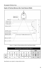
Depth of Field by Minimum Bar Code Element Width A mm .132 mils 5.2 MINIMUM BAR CODE ELEMENT WIDTH 1D PDF B C D E F G .19 .254 .33 .533 .254 .381 7.5 10.4 13 21 10 15.9 Specifications are subject to change without notice. 19 SCANNER OPERATION Depth of Field by Minimum Bar Code Element Width Figure 16.
Depth of Field by Minimum Bar Code Element Width A mm .132 mils 5.2 MINIMUM BAR CODE ELEMENT WIDTH 1D PDF B C D E F G .19 .254 .33 .533 .254 .381 7.5 10.4 13 21 10 15.9 Specifications are subject to change without notice. 19 SCANNER OPERATION Depth of Field by Minimum Bar Code Element Width Figure 16.


