
Owners Manual
Page 3
... starting 12 Starting the engine 12 Driving the machine 14 Cutting tips 15 Stopping the engine 16 Maintenance 17 Maintenance schedule 17 Dismantling of the machine hoods 18 Checking the engine's oil level 19 Checking the engine's cooling air intake .......... 19 Checking the fuel pump's air filter 19 Checking and adjusting the steering wires ...... 20 Checking and adjusting the brakes 20 Checking the transmission's oil level 21 Checking the battery acid level 21 Checking the safety system 21 Replacement of air filter 22 Checking and adjustment of cutting unit's ground pressure...
... starting 12 Starting the engine 12 Driving the machine 14 Cutting tips 15 Stopping the engine 16 Maintenance 17 Maintenance schedule 17 Dismantling of the machine hoods 18 Checking the engine's oil level 19 Checking the engine's cooling air intake .......... 19 Checking the fuel pump's air filter 19 Checking and adjusting the steering wires ...... 20 Checking and adjusting the brakes 20 Checking the transmission's oil level 21 Checking the battery acid level 21 Checking the safety system 21 Replacement of air filter 22 Checking and adjustment of cutting unit's ground pressure...

Owners Manual
Page 4
... parking brake before driving Speed limiter pedal forwards Neutral Speed limiter pedal reverse Switch off the engine and take off Battery Choke Fuel Oil pressure Cutting height Backwards Forwards Ignition Use eye and hearing protection Clutch in Clutch out Parking brake Hydrostatic free wheel ! Rotating blades. Brake Warning Soundlevel Warning! Drive very slowly without the cutting unit. Never carry passengers on the machine and in the operator's manual. Starting instructions Read the instructions Check the engine's oil level Check the hydrostat's oil level...
... parking brake before driving Speed limiter pedal forwards Neutral Speed limiter pedal reverse Switch off the engine and take off Battery Choke Fuel Oil pressure Cutting height Backwards Forwards Ignition Use eye and hearing protection Clutch in Clutch out Parking brake Hydrostatic free wheel ! Rotating blades. Brake Warning Soundlevel Warning! Drive very slowly without the cutting unit. Never carry passengers on the machine and in the operator's manual. Starting instructions Read the instructions Check the engine's oil level Check the hydrostat's oil level...

Owners Manual
Page 5
... during assembly and driving. • Never use it. • Wear approved protective glasses or a visor during reversing. • Keep an eye on the machine before starting to use the machine barefoot. Clear the area from stones etc. Failure to follow them carefully. Always switch off the blades, pull on the parking brake, stop quickly. • Read all the instructions in...
... during assembly and driving. • Never use it. • Wear approved protective glasses or a visor during reversing. • Keep an eye on the machine before starting to use the machine barefoot. Clear the area from stones etc. Failure to follow them carefully. Always switch off the blades, pull on the parking brake, stop quickly. • Read all the instructions in...

Owners Manual
Page 7
...emit sparks. • Check the fuel level each time before filling up with fuel in a boiler room or where there is running. Never fill up with fuel. Never allow children to drive the machine. • Be extra careful close to drive the machine. d. Children are toxic and highly ...cause the fuel to children in the fuel system the engine must not be started until this purpose. c. Never fill up the machine with fuel indoors. 5 English - e. RIDER 970 Never fill up with fuel when the engine is electrical equipment which obstruct your guard and switch off and...
...emit sparks. • Check the fuel level each time before filling up with fuel in a boiler room or where there is running. Never fill up with fuel. Never allow children to drive the machine. • Be extra careful close to drive the machine. d. Children are toxic and highly ...cause the fuel to children in the fuel system the engine must not be started until this purpose. c. Never fill up the machine with fuel indoors. 5 English - e. RIDER 970 Never fill up with fuel when the engine is electrical equipment which obstruct your guard and switch off and...

Owners Manual
Page 8
... battery. Check the parts regularly and if necessary replace them . • Check the functioning of naked flames or sparks. Wrap over an object. Adjust and maintain them . • Be extra careful when handling battery acid. Never drive the machine in the storage area. • Stop and inspect the equipment if you drive over the blades or use protective gloves when handling them with spare parts...
... battery. Check the parts regularly and if necessary replace them . • Check the functioning of naked flames or sparks. Wrap over an object. Adjust and maintain them . • Be extra careful when handling battery acid. Never drive the machine in the storage area. • Stop and inspect the equipment if you drive over the blades or use protective gloves when handling them with spare parts...
Owners Manual
Page 9
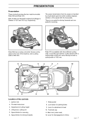
.... Lifting lever, cutting unit 5. Lever for disengagement of the speed with engines from the engine is one pedal for driving forwards and one pedal for parking brake 9. RIDER 850 RIDER 850 RIDER 970 Rider 850 has a cutting unit which enables stepless variation of drive 7 English - Adjustment of 850 mm. Lever for adjustment of the controls 1. The power transmission from Briggs & Stratton of 12.5 and 15.5 h.p. Ignition lock 2. Both models are...
.... Lifting lever, cutting unit 5. Lever for disengagement of the speed with engines from the engine is one pedal for driving forwards and one pedal for parking brake 9. RIDER 850 RIDER 850 RIDER 970 Rider 850 has a cutting unit which enables stepless variation of drive 7 English - Adjustment of 850 mm. Lever for adjustment of the controls 1. The power transmission from Briggs & Stratton of 12.5 and 15.5 h.p. Ignition lock 2. Both models are...
Owners Manual
Page 10
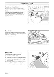
... with the throttle control, and thereby also the rotation speed of fuel and air, which simplifies cold start. Press down the brake pedal. 2. Speed limiter The speed of the machine is also used to drive forwards and pedal (2) for reversing. 2 1 RIDER 850 Parking brake The parking brake is adjusted with two pedals. Pedal (1) is used the engine receives a richer mixture of the blades. PRESENTATION Throttle and Choke lever The engine speed is applied...
... with the throttle control, and thereby also the rotation speed of fuel and air, which simplifies cold start. Press down the brake pedal. 2. Speed limiter The speed of the machine is also used to drive forwards and pedal (2) for reversing. 2 1 RIDER 850 Parking brake The parking brake is adjusted with two pedals. Pedal (1) is used the engine receives a richer mixture of the blades. PRESENTATION Throttle and Choke lever The engine speed is applied...

Owners Manual
Page 13
English - 11 Fuelling The engine should be adjusted lengthways. WARNING! The seat can be tipped forward. Petrol/gasoline is highly inflammable. PRESENTATION Seat, Rider 970 HST The seat has a jointed attachment on the front edge and can also be run on at least 92 octane leaded or unleaded petrol/gasoline (not oil mixed). ! Lock the setting with fuel outdoors (see safety instructions). Observe care and fill up with the knobs. Release the knobs under the seat and adjust it forwards or backwards to the required position.
English - 11 Fuelling The engine should be adjusted lengthways. WARNING! The seat can be tipped forward. Petrol/gasoline is highly inflammable. PRESENTATION Seat, Rider 970 HST The seat has a jointed attachment on the front edge and can also be run on at least 92 octane leaded or unleaded petrol/gasoline (not oil mixed). ! Lock the setting with fuel outdoors (see safety instructions). Observe care and fill up with the knobs. Release the knobs under the seat and adjust it forwards or backwards to the required position.

Owners Manual
Page 14
... the brake pedal (1). • Press in the lock button on page 17). Push the throttle control to the required position. Adjust the seat to position 3 (choke position). Lift up the cutting unit by pulling the lever backwards to locked position (transport position). 2. English DRIVING • Read the safety instructions and information on the location and function of the controls before starting (see pages 3-11). • Conduct daily maintenance before starting (see maintenance schedule...
... the brake pedal (1). • Press in the lock button on page 17). Push the throttle control to the required position. Adjust the seat to position 3 (choke position). Lift up the cutting unit by pulling the lever backwards to locked position (transport position). 2. English DRIVING • Read the safety instructions and information on the location and function of the controls before starting (see pages 3-11). • Conduct daily maintenance before starting (see maintenance schedule...

Owners Manual
Page 15
... engine has started release the ignition key to the required speed. Push the throttle control to neutral position. Never run the starter for more than about 10 seconds before trying again. 6. If the engine does not start position. STOP START STOP START English - 13 DRIVING Warm engine: 4. Turn the ignition key to full throttle. ! The exhaust fumes contain toxic carbon monoxide. For cutting 3/4 to start , wait about 5 seconds at a time. WARNING! Set the throttle control...
... engine has started release the ignition key to the required speed. Push the throttle control to neutral position. Never run the starter for more than about 10 seconds before trying again. 6. If the engine does not start position. STOP START STOP START English - 13 DRIVING Warm engine: 4. Turn the ignition key to full throttle. ! The exhaust fumes contain toxic carbon monoxide. For cutting 3/4 to start , wait about 5 seconds at a time. WARNING! Set the throttle control...
Owners Manual
Page 19
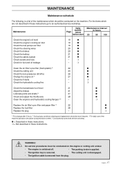
... Check the fuel pump's air filter Check the steering wires Check the brakes Check the battery Check the safety system Check screws and nuts Check for fuel and oil leakage 19 q 19 q 19 q 20 q 20 q 21 q 21 q - Maintenance Daily maintePage nance before start Maintenance interval in these instructions. r Replace the air filter's pre-filter and paper filter 2) 22 q Replace the fuel filter 28 q Replace the plug - r Clean the air filter's pre-filter (foam plastic) 2) 22 q Check the cutting unit 23 q Check the tyre pressures (60 kPa) 26 q Change the engine...
... Check the fuel pump's air filter Check the steering wires Check the brakes Check the battery Check the safety system Check screws and nuts Check for fuel and oil leakage 19 q 19 q 19 q 20 q 20 q 21 q 21 q - Maintenance Daily maintePage nance before start Maintenance interval in these instructions. r Replace the air filter's pre-filter and paper filter 2) 22 q Replace the fuel filter 28 q Replace the plug - r Clean the air filter's pre-filter (foam plastic) 2) 22 q Check the cutting unit 23 q Check the tyre pressures (60 kPa) 26 q Change the engine...

Owners Manual
Page 21
... the fuel pump's air filter Check regularly that the cooling intake is free from dirt. If the level approaches the ADD mark, top up with a brush. Release the dip stick and pull out. FULL Checking of the engine, which can when necessary be fully screwed down. The dip stick must be cleaned with oil to the FULL mark. The filter can damage the engine. MAINTENANCE Check the engine's oil level Check the oil level...
... the fuel pump's air filter Check regularly that the cooling intake is free from dirt. If the level approaches the ADD mark, top up with a brush. Release the dip stick and pull out. FULL Checking of the engine, which can when necessary be fully screwed down. The dip stick must be cleaned with oil to the FULL mark. The filter can damage the engine. MAINTENANCE Check the engine's oil level Check the oil level...

Owners Manual
Page 25
.... If the values are the same the cutting unit is conducted as follows: 1. MAINTENANCE Checking and adjustment of bathroom scales under the cutting unit's frame (front edge) so that the support wheels do not bear any weight. 2. Place a set of the cutting unit's ground pressure Rider 970 To achieve the best cutting results the cutting unit should be placed between 12 and 15...
.... If the values are the same the cutting unit is conducted as follows: 1. MAINTENANCE Checking and adjustment of bathroom scales under the cutting unit's frame (front edge) so that the support wheels do not bear any weight. 2. Place a set of the cutting unit's ground pressure Rider 970 To achieve the best cutting results the cutting unit should be placed between 12 and 15...

Owners Manual
Page 27
... machine for cleaning or checking of the cutting unit takes place in against the crossbar and then set the cutting height to dismantling. ! Remove the hair-needle spring and release the crossbar (6) from the chain retainer. 6. Make sure to the transport position. 3. Push the stop (1) in the reverse order to the lowest position. Fitting of the blades and screws. 1 Dismantle the cutting unit...
... machine for cleaning or checking of the cutting unit takes place in against the crossbar and then set the cutting height to dismantling. ! Remove the hair-needle spring and release the crossbar (6) from the chain retainer. 6. Make sure to the transport position. 3. Push the stop (1) in the reverse order to the lowest position. Fitting of the blades and screws. 1 Dismantle the cutting unit...
Owners Manual
Page 30
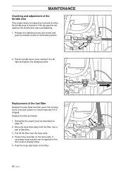
.... Pull off the filter from the filter. MAINTENANCE Checking and adjustment of the throttle wire If the engine does not respond as it is not reached, the throttle wire may need adjusting. 1. Replacement of flat pliers. 3. If necessary soap solution can be applied on page 18. 2. Press in the new filter on the filter. 28 - Replace the filter as described on the filter ends to full throttle position. 2. Use a pair of the fuel filter Replace the...
.... Pull off the filter from the filter. MAINTENANCE Checking and adjustment of the throttle wire If the engine does not respond as it is not reached, the throttle wire may need adjusting. 1. Replacement of flat pliers. 3. If necessary soap solution can be applied on page 18. 2. Press in the new filter on the filter. 28 - Replace the filter as described on the filter ends to full throttle position. 2. Use a pair of the fuel filter Replace the...

Owners Manual
Page 31
... power. • Air filter clogged. • Plug defective. • Dirt in wrong position. • Main fuse blown. English - 29 Engine does not run smoothly. • Wrong gear, too high. • Carburettor incorrectly set . Starter does not pull round engine. • Battery flat. • Bad contact between battery terminals and cables. Uneven mowing. • Blades blunt. • Cutting unit skew. • Long or wet grass. • Grass blockage under the battery cover. • Ignition lock...
... power. • Air filter clogged. • Plug defective. • Dirt in wrong position. • Main fuse blown. English - 29 Engine does not run smoothly. • Wrong gear, too high. • Carburettor incorrectly set . Starter does not pull round engine. • Battery flat. • Bad contact between battery terminals and cables. Uneven mowing. • Blades blunt. • Cutting unit skew. • Long or wet grass. • Grass blockage under the battery cover. • Ignition lock...

Owners Manual
Page 32
... distribute the oil and screw the plug back on. 6. Start the engine and run it until the carburettor is a clean and dry place and cover it is a good way of getting the best out of your machine the next season. Always use petrol for extra protection. RIDER 970 RIDER 850 RIDER 850 30 - Drain off the fuel in each cylinder. Remove the battery. Fuel stabiliser...
... distribute the oil and screw the plug back on. 6. Start the engine and run it until the carburettor is a clean and dry place and cover it is a good way of getting the best out of your machine the next season. Always use petrol for extra protection. RIDER 970 RIDER 850 RIDER 850 30 - Drain off the fuel in each cylinder. Remove the battery. Fuel stabiliser...

Owners Manual
Page 33
gradient Engine Manufacture Power Displacement Fuel Tank volume Oil Oil volume Start Electrical system Type Battery Spark plug Transmission Manufacture Oil Cutting unit Type Cutting width (Bioclip) Cutting height Blade diameter (Bioclip) NOISE LEVEL Rider 850 2000 mm 960 mm 1060 mm 225 kg 820 mm 625 mm 16 x 6.50 x 8 60 kPa (0.6 kp/cm2) 15° Rider 970 2145 mm 1050 mm (970-15.5), 1260 mm (970-15.5S) 1120 (970-Bioclip) 1060 mm 240...
gradient Engine Manufacture Power Displacement Fuel Tank volume Oil Oil volume Start Electrical system Type Battery Spark plug Transmission Manufacture Oil Cutting unit Type Cutting width (Bioclip) Cutting height Blade diameter (Bioclip) NOISE LEVEL Rider 850 2000 mm 960 mm 1060 mm 225 kg 820 mm 625 mm 16 x 6.50 x 8 60 kPa (0.6 kp/cm2) 15° Rider 970 2145 mm 1050 mm (970-15.5), 1260 mm (970-15.5S) 1120 (970-Bioclip) 1060 mm 240...

Parts Manual
Page 2
... WHEEL CHOKE BLADE GUARD GROMMET COMPRESSION SPRING TANK CAP ASSY COMPRESSION SPRING STARTER PULLEY RECOIL SPRING WHEEL SPACING SLEEVE FUEL FILTER FUEL FILTER ASSY HOSE CLAMP WEAR PROTECTION PULLEY BELT TENSIONER ASSY BELT GUARD GASKET NIPPLE FILTER SPACING SLEEVE SPACING SLEEVE DRIVER BUMPER DRIVER COVER PLATE LABLE SPACER TUBE SPACING SLEEVE SPACING SLEEVE DUST COVER STOP SWITCH WASHER LOCKING BUTTON THREAD BUSHING SPACER TUBE SPACER TUBE ROLLER SPACER LEVER LEVER SPACER STARTER CORD STARTER CORD SEALING RING BOLT WIPER WASHER SCREW COMPRESSION SPRING SEALING BRACKET ASSY DRIVE SHAFT LEVER...
... WHEEL CHOKE BLADE GUARD GROMMET COMPRESSION SPRING TANK CAP ASSY COMPRESSION SPRING STARTER PULLEY RECOIL SPRING WHEEL SPACING SLEEVE FUEL FILTER FUEL FILTER ASSY HOSE CLAMP WEAR PROTECTION PULLEY BELT TENSIONER ASSY BELT GUARD GASKET NIPPLE FILTER SPACING SLEEVE SPACING SLEEVE DRIVER BUMPER DRIVER COVER PLATE LABLE SPACER TUBE SPACING SLEEVE SPACING SLEEVE DUST COVER STOP SWITCH WASHER LOCKING BUTTON THREAD BUSHING SPACER TUBE SPACER TUBE ROLLER SPACER LEVER LEVER SPACER STARTER CORD STARTER CORD SEALING RING BOLT WIPER WASHER SCREW COMPRESSION SPRING SEALING BRACKET ASSY DRIVE SHAFT LEVER...

Parts Manual
Page 3
... CAP CAP KNOB COMBINATION TOOL NIPPLE WATER BLADE LUBRICATION GUN HOSE ASSY VALVE ASSY IGNITION CABLE CHASSIS PIN SEALING PISTON GASKET INLET PIPE PLATE CUP SHAFT SHAFT COVER BEARING CAGE IGNITION MODULE FILTER CONNECTION AIR FILTER THROTTLE LOCK OUT INLET PIPE HOLDER ASSY RUBBER BUSHING FLANGE INLET PIPE CARBURETTOR HANDLE DECAL DECAL DECAL START INSTRUCTION SEALING DRIVING PULLEY ASSY DECAL BALL BEARING FUEL HOSE COVER CABLE LEVER SPRING ANTIVIBRATION ELEMENT ANTIVIBRATION ELEMENT ANTIVIBRATION ELEMENT TANK VENT ASSY AIR PURGE SCREW SLEEVE GREASE BELT GUIDE...
... CAP CAP KNOB COMBINATION TOOL NIPPLE WATER BLADE LUBRICATION GUN HOSE ASSY VALVE ASSY IGNITION CABLE CHASSIS PIN SEALING PISTON GASKET INLET PIPE PLATE CUP SHAFT SHAFT COVER BEARING CAGE IGNITION MODULE FILTER CONNECTION AIR FILTER THROTTLE LOCK OUT INLET PIPE HOLDER ASSY RUBBER BUSHING FLANGE INLET PIPE CARBURETTOR HANDLE DECAL DECAL DECAL START INSTRUCTION SEALING DRIVING PULLEY ASSY DECAL BALL BEARING FUEL HOSE COVER CABLE LEVER SPRING ANTIVIBRATION ELEMENT ANTIVIBRATION ELEMENT ANTIVIBRATION ELEMENT TANK VENT ASSY AIR PURGE SCREW SLEEVE GREASE BELT GUIDE...


