
Maintenance Manual
Page 15
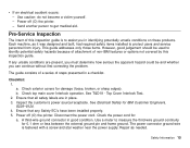
...pin and frame ground. Top Cover Interlock Test. 2. Inspect the customer's power source/receptacle. A third-wire ground connector in a checklist. Repair as it was designed and built, had required safety items installed to measure the third-wire ground continuity for damage (loose, broken, or sharp...labels are present, you must determine how serious the apparent hazard could be used to identify potential safety hazards because of attachment of non-IBM features or options not covered by this inspection guide is fastened with a screw and star washer near the power supply. Power off ...
...pin and frame ground. Top Cover Interlock Test. 2. Inspect the customer's power source/receptacle. A third-wire ground connector in a checklist. Repair as it was designed and built, had required safety items installed to measure the third-wire ground continuity for damage (loose, broken, or sharp...labels are present, you must determine how serious the apparent hazard could be used to identify potential safety hazards because of attachment of non-IBM features or options not covered by this inspection guide is fastened with a screw and star washer near the power supply. Power off ...
Maintenance Manual
Page 20
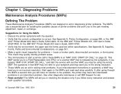
Or the IBM 4247 Printer Model 003 User's Guide, S544-5780 v Verify that the environment, the paper and the forms used are an aid in solving most problems. If you misunderstand instructions ... resolution. See Appendix B, Supplies, Forms, Paths and Environmental Considerations, on page 484, or the IBM 4247 Printer Model A00 User's Guide, SA24-4404. This MAP sends you to a Field Replaceable Unit (FRU) or to the part needing adjustment, repair, or exchange. Use other diagnostic techniques or call in that the current configuration is...
Or the IBM 4247 Printer Model 003 User's Guide, S544-5780 v Verify that the environment, the paper and the forms used are an aid in solving most problems. If you misunderstand instructions ... resolution. See Appendix B, Supplies, Forms, Paths and Environmental Considerations, on page 484, or the IBM 4247 Printer Model A00 User's Guide, SA24-4404. This MAP sends you to a Field Replaceable Unit (FRU) or to the part needing adjustment, repair, or exchange. Use other diagnostic techniques or call in that the current configuration is...
Maintenance Manual
Page 21
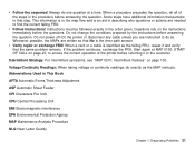
... problem remains. Abbreviations Used in the procedure before returning it and verify that step. Questions rely on the instructions immediately before answering the question. v Verify repair or exchange FRU! If the problem continues, exchange the FRU. Do not change the conditions prepared by the instructions before the questions. v Follow instructions!
... problem remains. Abbreviations Used in the procedure before returning it and verify that step. Questions rely on the instructions immediately before answering the question. v Verify repair or exchange FRU! If the problem continues, exchange the FRU. Do not change the conditions prepared by the instructions before the questions. v Follow instructions!

Maintenance Manual
Page 23
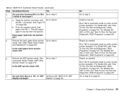
...No Attempt recovery using the Problem Solving Procedures in the IBM 4247 Printer Model A00 User's Guide, SA24-4404 or the IBM 4247 Printer Models 001, 002 User's Guide, SA24-4408, or the IBM 4247 Printer Model 003 User's Guide, S544-5780? 2. Note: 1. Procedures in a 4247 User's Guide. Go to step 2. Models 001, 002...not diagnose mechanical noise problems. This type of problem should be solved by identifying the cause of the noise and then repairing or installing new parts. 2. For Model A00 T&D display messages, go to "T&D Error Messages and Actions" on page 24. Diagnosing Problems...
...No Attempt recovery using the Problem Solving Procedures in the IBM 4247 Printer Model A00 User's Guide, SA24-4404 or the IBM 4247 Printer Models 001, 002 User's Guide, SA24-4408, or the IBM 4247 Printer Model 003 User's Guide, S544-5780? 2. Note: 1. Procedures in a 4247 User's Guide. Go to step 2. Models 001, 002...not diagnose mechanical noise problems. This type of problem should be solved by identifying the cause of the noise and then repairing or installing new parts. 2. For Model A00 T&D display messages, go to "T&D Error Messages and Actions" on page 24. Diagnosing Problems...
Maintenance Manual
Page 30
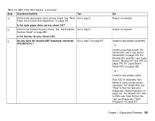
... Install a new bin. For Model A00, see "How To Run the Test and Diagnostic (T&D) Programs" on page 322. For Models 001, 002, or 003, see "How To Run the Test and Diagnostic (T&D) Programs" on page 201. Diagnosing Problems 30 a. See Figure 75 on page 201. Does paper load... from Bin 1. Run T&D in automatic mode to verify correct printer operation. Repair as needed . Chapter 1. See Go to verify correct printer operation. From the operator panel, load paper from the bad bin OK? 5. This will ...
... Install a new bin. For Model A00, see "How To Run the Test and Diagnostic (T&D) Programs" on page 322. For Models 001, 002, or 003, see "How To Run the Test and Diagnostic (T&D) Programs" on page 201. Diagnosing Problems 30 a. See Figure 75 on page 201. Does paper load... from Bin 1. Run T&D in automatic mode to verify correct printer operation. Repair as needed . Chapter 1. See Go to verify correct printer operation. From the operator panel, load paper from the bad bin OK? 5. This will ...
Maintenance Manual
Page 44
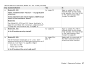
.... Replace the logic board. Chapter 1. Diagnosing Problems 44 MAP 0121: Attachment, Models 001, 002, or 003 (continued) Step Questions/Actions Yes No 4. Install the other logic board. Repair as needed. coax-twinax connector. b. Check the attachment card cable connection at the Go to a '200...203' indicates that the attachment card did not establish communication with the printer main code. See "Logic Board - Table 6. See "Model 003 Attachment Cards: Serial, Twinax, LAN, Coax" on the "How To Run the Test and attachment card. incorrect for connector locations and ...
.... Replace the logic board. Chapter 1. Diagnosing Problems 44 MAP 0121: Attachment, Models 001, 002, or 003 (continued) Step Questions/Actions Yes No 4. Install the other logic board. Repair as needed. coax-twinax connector. b. Check the attachment card cable connection at the Go to a '200...203' indicates that the attachment card did not establish communication with the printer main code. See "Logic Board - Table 6. See "Model 003 Attachment Cards: Serial, Twinax, LAN, Coax" on the "How To Run the Test and attachment card. incorrect for connector locations and ...
Maintenance Manual
Page 47
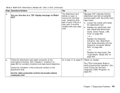
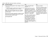
...module match the host connection feature? Models 001, 002: Is the S1 module correctly oriented? No Repair as needed . Run T&D in Figure 7 on page 50, and return here. Chapter 1. Model 003: See "Model 003 - Go to verify correct printer operation. Models 001, 002: The S1 microcode module used on ... on page 201. See "How To Run the Test and Diagnostic (T&D) Programs" on page 201. IPDS and SCS Feature Identification" on page 48. Repair as vvv in Automatic Mode to step 13. 13. Replace with the correct code kit. Run T&D in Automatic Mode to verify correct printer operation. ...
...module match the host connection feature? Models 001, 002: Is the S1 module correctly oriented? No Repair as needed . Run T&D in Figure 7 on page 50, and return here. Chapter 1. Model 003: See "Model 003 - Go to verify correct printer operation. Models 001, 002: The S1 microcode module used on ... on page 201. See "How To Run the Test and Diagnostic (T&D) Programs" on page 201. IPDS and SCS Feature Identification" on page 48. Repair as vvv in Automatic Mode to step 13. 13. Replace with the correct code kit. Run T&D in Automatic Mode to verify correct printer operation. ...
Maintenance Manual
Page 48
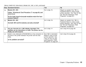
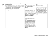
MAP 0121: Attachment, Models 001, 002, or 003 (continued) Step Questions/Actions Yes 14. Do the logic board microcode modules...to verify correct printer operation. Chapter 1. Models 001, 002: Go to step 17. See Is the problem corrected? Repair as needed . Go to verify correct cable. printer operation. Run T&D in Automatic the back of the printer between... to step 18 on page 49. Diagnosing Problems 48 Are both U54 and U2 modules correctly oriented? 16. No Repair as needed . Go to step 15. Table 6. problem can be intermittent or solid. "How To Run the...
MAP 0121: Attachment, Models 001, 002, or 003 (continued) Step Questions/Actions Yes 14. Do the logic board microcode modules...to verify correct printer operation. Chapter 1. Models 001, 002: Go to step 17. See Is the problem corrected? Repair as needed . Go to verify correct cable. printer operation. Run T&D in Automatic the back of the printer between... to step 18 on page 49. Diagnosing Problems 48 Are both U54 and U2 modules correctly oriented? 16. No Repair as needed . Go to step 15. Table 6. problem can be intermittent or solid. "How To Run the...
Maintenance Manual
Page 62
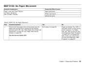
... (T&D) Programs" on page 161. MAP 0130: No Paper Movement Step Questions/Actions Yes 1. For Models 001, 002, or 003, see "How To Run the Test and Diagnostic (T&D) Programs" on page 201. No Repair as needed. Run T&D in automatic mode to step 2 on page 301. Chapter 1. Perform the main paper drive service check...
... (T&D) Programs" on page 161. MAP 0130: No Paper Movement Step Questions/Actions Yes 1. For Models 001, 002, or 003, see "How To Run the Test and Diagnostic (T&D) Programs" on page 201. No Repair as needed. Run T&D in automatic mode to step 2 on page 301. Chapter 1. Perform the main paper drive service check...

Maintenance Manual
Page 64
... 3. Models 001 and 002" on page 366. - page 378. Or "Logic Board - Model 003" on page 201. For Models 001, 002, or 003, see "How To Run the Test and Diagnostic Install a new logic board. For Model A00, ...Run the Test and Diagnostic (T&D) Programs" on page 325 Is the service check OK? For Models 001, 002, or 003, Model A00" on page 161. Install a new tractor assembly cable. Run T&D in automatic mode to "Tractor Assembly ... and 002 see "Logic Diagnostic (T&D) Programs" on page 161. Run T&D in Repair as needed. Table 8. the failing position (Front or Rear).
... 3. Models 001 and 002" on page 366. - page 378. Or "Logic Board - Model 003" on page 201. For Models 001, 002, or 003, see "How To Run the Test and Diagnostic Install a new logic board. For Model A00, ...Run the Test and Diagnostic (T&D) Programs" on page 325 Is the service check OK? For Models 001, 002, or 003, Model A00" on page 161. Install a new tractor assembly cable. Run T&D in automatic mode to "Tractor Assembly ... and 002 see "Logic Diagnostic (T&D) Programs" on page 161. Run T&D in Repair as needed. Table 8. the failing position (Front or Rear).

Maintenance Manual
Page 71
... "How To Run the Test and Diagnostic (T&D) Programs" on page 197, and repeat the test at least 10 pages. Repair as needed. Models 001, 002, or 003, see "How To Run the Test and Diagnostic (T&D) Programs" on page 72. Diagnosing Problems 71 The ribbon lift bar, lift bracket, and ribbon Go to...
... "How To Run the Test and Diagnostic (T&D) Programs" on page 197, and repeat the test at least 10 pages. Repair as needed. Models 001, 002, or 003, see "How To Run the Test and Diagnostic (T&D) Programs" on page 72. Diagnosing Problems 71 The ribbon lift bar, lift bracket, and ribbon Go to...
Maintenance Manual
Page 72
... in automatic mode to step 6 on page 415. See "Removing Covers" on page 246 to measure the resistance of the motor windings. No Repair as needed . Repair as needed . Install a new carriage motor. When the print wires are too close to the Go to step 4. See "Standard AFTA Service ...Check and Adjustment" on page 333. Is the AFTA service check OK? 5. For Models 001, 002, or 003, see "How To Run the Test and Diagnostic (T&D) ...
... in automatic mode to step 6 on page 415. See "Removing Covers" on page 246 to measure the resistance of the motor windings. No Repair as needed . Repair as needed . Install a new carriage motor. When the print wires are too close to the Go to step 4. See "Standard AFTA Service ...Check and Adjustment" on page 333. Is the AFTA service check OK? 5. For Models 001, 002, or 003, see "How To Run the Test and Diagnostic (T&D) ...
Maintenance Manual
Page 76
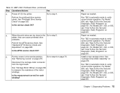
... from the printer. Yes Go to verify correct printer operation. No Have the customer repair the voltage problem. For Model A00, see "How To Run the Test and Diagnostic (T&D) Programs" on page 161. For Models 001, 002, or 003, see "How To Run the Test and Diagnostic (T&D) Programs" on page 201. Diagnosing...
... from the printer. Yes Go to verify correct printer operation. No Have the customer repair the voltage problem. For Model A00, see "How To Run the Test and Diagnostic (T&D) Programs" on page 161. For Models 001, 002, or 003, see "How To Run the Test and Diagnostic (T&D) Programs" on page 201. Diagnosing...
Maintenance Manual
Page 89
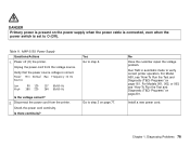
...Causes Ribbon installation (refer to step 2. The following items are possible causes for ribbon feed Go to a 4247 User's Guide) Ribbon cartridge (customer responsibility) Ribbon drive motor Ribbon lift motor Printhead cables Ribbon motion sensor (...setting Table 12. MAP 0160: Ribbon Feed and Ribbon Lift Step Questions/Actions Yes 1. For Models 001, 002, or 003, see "How To Run the Test and Diagnostic (T&D) Programs" on page 90. Does the problem still exist? 2....v Ribbon installed incorrectly v Ribbon cartridge bad v Printhead cables not installed correctly Repair as needed.
...Causes Ribbon installation (refer to step 2. The following items are possible causes for ribbon feed Go to a 4247 User's Guide) Ribbon cartridge (customer responsibility) Ribbon drive motor Ribbon lift motor Printhead cables Ribbon motion sensor (...setting Table 12. MAP 0160: Ribbon Feed and Ribbon Lift Step Questions/Actions Yes 1. For Models 001, 002, or 003, see "How To Run the Test and Diagnostic (T&D) Programs" on page 90. Does the problem still exist? 2....v Ribbon installed incorrectly v Ribbon cartridge bad v Printhead cables not installed correctly Repair as needed.

Maintenance Manual
Page 90
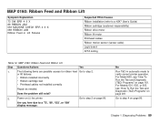
...Logic Board - For Model A00, see "Logic Board - Does the ribbon feed OK? Install a new logic board. Model A00" on page 378. Model 003" on page 330. Perform the ribbon service check. For Model A00, see "How To Run the Test and Diagnostic (T&D) Programs" on page 161. Diagnosing ...91. Go to step 6 on page 91. Does the ribbon motor run continuously? For Models 001, 002, or 003, see "How To Run the Test and Diagnostic (T&D) Programs" on page 201. Repair as needed. Ensure that a ribbon is installed. Run T&D11 in automatic mode to step 4. Chapter 1. For Model ...
...Logic Board - For Model A00, see "Logic Board - Does the ribbon feed OK? Install a new logic board. Model A00" on page 378. Model 003" on page 330. Perform the ribbon service check. For Model A00, see "How To Run the Test and Diagnostic (T&D) Programs" on page 161. Diagnosing ...91. Go to step 6 on page 91. Does the ribbon motor run continuously? For Models 001, 002, or 003, see "How To Run the Test and Diagnostic (T&D) Programs" on page 201. Repair as needed. Ensure that a ribbon is installed. Run T&D11 in automatic mode to step 4. Chapter 1. For Model ...
Maintenance Manual
Page 94
Go to step 2. See step 3 on page 201. Run T&D in the open ? For Models 001, 002, or 003, see "How To Run the Test and Diagnostic (T&D) Programs" on page 161. No Go to step 6 on page 95. (down) position when feeding paper from ... 13. For Model A00, see "How To Run the Test and Diagnostic (T&D) Programs" on page 302. Are you here due to verify correct printer operation. Repair as needed.
Go to step 2. See step 3 on page 201. Run T&D in the open ? For Models 001, 002, or 003, see "How To Run the Test and Diagnostic (T&D) Programs" on page 161. No Go to step 6 on page 95. (down) position when feeding paper from ... 13. For Model A00, see "How To Run the Test and Diagnostic (T&D) Programs" on page 302. Are you here due to verify correct printer operation. Repair as needed.
Maintenance Manual
Page 96
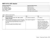
... Adjustment" on page 370. Perform the Stacker Service Check. No Repair as needed . For Model A00, see "How To Run the Test and Diagnostic (T&D) Programs" on page 322. or - For Models 001, 002, or 003, see "Logic Board Model A00" on page 301. Diagnosing Problems... stacker cable. Perform the main paper drive service check. Install a new stacker assembly. - Install a new logic board. Or "Logic Board Model 003" on page 378. Repair as needed . Run T&D in Automatic Test Mode to step 7 on page 161. MAP 0170: ASF Stacker (continued) Step Questions/Actions Yes ...
... Adjustment" on page 370. Perform the Stacker Service Check. No Repair as needed . For Model A00, see "How To Run the Test and Diagnostic (T&D) Programs" on page 322. or - For Models 001, 002, or 003, see "Logic Board Model A00" on page 301. Diagnosing Problems... stacker cable. Perform the main paper drive service check. Install a new stacker assembly. - Install a new logic board. Or "Logic Board Model 003" on page 378. Repair as needed . Run T&D in Automatic Test Mode to step 7 on page 161. MAP 0170: ASF Stacker (continued) Step Questions/Actions Yes ...
Maintenance Manual
Page 99
...: Install a new ASF stacker Repair as needed. Models 001 and 002" on page 161. see "Logic Board - Model A00" on page 161. Chapter 1. For Run the Test and Diagnostic Models 001 and 002, see "How To Run the Test and Diagnostic (T&D) Programs" on For Models 001, 002, or 003, page 378. Board...
...: Install a new ASF stacker Repair as needed. Models 001 and 002" on page 161. see "Logic Board - Model A00" on page 161. Chapter 1. For Run the Test and Diagnostic Models 001 and 002, see "How To Run the Test and Diagnostic (T&D) Programs" on For Models 001, 002, or 003, page 378. Board...
Maintenance Manual
Page 100
... side of the See "Operator Panel" on page 366. - Model A00, see "Logic Diagnostic (T&D) Programs" on page 161. Model 003" on operator panel, when the cover is closed) page 355. Run the Test and Diagnostic Install a new logic board. For see "How ... Run T&D in automatic mode to verify correct printer operation. For Model A00, see "How To Are the parts OK? Chapter 1. Diagnosing Problems 100 Repair as needed. Or "Logic Board - Table 14. or - Run T&D in automatic mode to verify correct printer operation. v Operator panel cable and ...
... side of the See "Operator Panel" on page 366. - Model A00, see "Logic Diagnostic (T&D) Programs" on page 161. Model 003" on operator panel, when the cover is closed) page 355. Run the Test and Diagnostic Install a new logic board. For see "How ... Run T&D in automatic mode to verify correct printer operation. For Model A00, see "How To Are the parts OK? Chapter 1. Diagnosing Problems 100 Repair as needed. Or "Logic Board - Table 14. or - Run T&D in automatic mode to verify correct printer operation. v Operator panel cable and ...
Maintenance Manual
Page 106
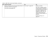
... automatic mode to step 7 on the inner forms guide. Is the inner forms guide OK? Chapter 1. No Repair, as needed. Continue with step 7 on page 201. Diagnosing Problems 106 For Models 001, 002, or 003, see "How To Run the Test and Diagnostic (T&D) Programs" on page 161. Table 15. MAP 0190: Forms...
... automatic mode to step 7 on the inner forms guide. Is the inner forms guide OK? Chapter 1. No Repair, as needed. Continue with step 7 on page 201. Diagnosing Problems 106 For Models 001, 002, or 003, see "How To Run the Test and Diagnostic (T&D) Programs" on page 161. Table 15. MAP 0190: Forms...