
Product Specification
Page 8
...3.5 Legacy USB Support 61 3.6 BIOS Updates 62 3.6.1 Language Support 62 3.6.2 Custom Splash Screen 63 3.7 BIOS Recovery 63 3.8 Boot Options 64 3.8.1 Optical Drive Boot 64 3.8.2 Network Boot 64 3.8.3 Booting Without Attached Devices 64 3.8.4 Changing the Default Boot Device During POST 64 3.9 Adjusting Boot Speed 65 3.9.1 Peripheral Selection and Configuration 65 3.9.2 BIOS Boot Optimizations 65 3.10 BIOS Security Features 66 3.11 BIOS Performance Features 67 4 Error Messages and Beep Codes 4.1 Speaker 69 4.2 BIOS Beep Codes 69 4.3 Front-panel Power LED Blink Codes 70 4.4 BIOS...
...3.5 Legacy USB Support 61 3.6 BIOS Updates 62 3.6.1 Language Support 62 3.6.2 Custom Splash Screen 63 3.7 BIOS Recovery 63 3.8 Boot Options 64 3.8.1 Optical Drive Boot 64 3.8.2 Network Boot 64 3.8.3 Booting Without Attached Devices 64 3.8.4 Changing the Default Boot Device During POST 64 3.9 Adjusting Boot Speed 65 3.9.1 Peripheral Selection and Configuration 65 3.9.2 BIOS Boot Optimizations 65 3.10 BIOS Security Features 66 3.11 BIOS Performance Features 67 4 Error Messages and Beep Codes 4.1 Speaker 69 4.2 BIOS Beep Codes 69 4.3 Front-panel Power LED Blink Codes 70 4.4 BIOS...
Product Specification
Page 9
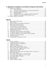
... 3. Memory Channel and DIMM Configuration 20 4. LAN Connector LED Locations 27 6. Location of the Jumper Block 50 14. Location of the Standby Power LED 36 8. Supported Memory Configurations 18 4. Power States and Targeted System Power 31 8. Thermal Sensors and Fan Headers 29 7. Detailed System Memory Address Map 38 9. Back Panel Connectors 40 10. Board Dimensions 52 15. LAN Connector LED States 27 6. Component-side Connectors and Headers Shown in Figure 1 14 3. IEEE 1394a Header 43 12. Front Panel Audio Header for Front Panel USB 2.0 Headers...
... 3. Memory Channel and DIMM Configuration 20 4. LAN Connector LED Locations 27 6. Location of the Jumper Block 50 14. Location of the Standby Power LED 36 8. Supported Memory Configurations 18 4. Power States and Targeted System Power 31 8. Thermal Sensors and Fan Headers 29 7. Detailed System Memory Address Map 38 9. Back Panel Connectors 40 10. Board Dimensions 52 15. LAN Connector LED States 27 6. Component-side Connectors and Headers Shown in Figure 1 14 3. IEEE 1394a Header 43 12. Front Panel Audio Header for Front Panel USB 2.0 Headers...
Product Specification
Page 10
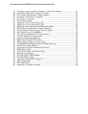
... and User Password Functions 66 38. Port 80h POST Code Ranges 71 42. Intel Desktop Board DP67DE Technical Product Specification 18. Safety Standards 77 45. BIOS Setup Configuration Jumper Settings 51 28. Boot Device Menu Options 64 37. States for a One-Color Power LED 48 25. Regulatory Compliance Marks 85 x Processor Core Power Connector 46 22. Alternate Front Panel Power/Sleep LED Header 48 27. Fan Header Current Capability 54 30. Port 80h POST Codes 72 43. EMC Regulations 81 46. Processor, Front, and Rear Chassis (4-Pin) Fan Headers...
... and User Password Functions 66 38. Port 80h POST Code Ranges 71 42. Intel Desktop Board DP67DE Technical Product Specification 18. Safety Standards 77 45. BIOS Setup Configuration Jumper Settings 51 28. Boot Device Menu Options 64 37. States for a One-Color Power LED 48 25. Regulatory Compliance Marks 85 x Processor Core Power Connector 46 22. Alternate Front Panel Power/Sleep LED Header 48 27. Fan Header Current Capability 54 30. Port 80h POST Codes 72 43. EMC Regulations 81 46. Processor, Front, and Rear Chassis (4-Pin) Fan Headers...

Product Specification
Page 11
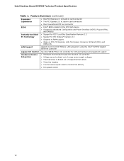
... memory technology • Support for up to 95W TDP in graphics card 10-channel (7.1 + 2) Intel High Definition Audio via the Realtek ALC892 audio codec • Two USB 3.0 ports are implemented with stacked back panel connectors (blue) • Fourteen USB 2.0 ports: ― Six ports are implemented with stacked back panel connectors (black) ― Eight front panel ports implemented through four internal headers • Two SATA 6.0 Gb/s interfaces through Intel P67 Express Chipset with Intel® Rapid Storage Technology RAID support (blue) • Four Serial...
... memory technology • Support for up to 95W TDP in graphics card 10-channel (7.1 + 2) Intel High Definition Audio via the Realtek ALC892 audio codec • Two USB 3.0 ports are implemented with stacked back panel connectors (blue) • Fourteen USB 2.0 ports: ― Six ports are implemented with stacked back panel connectors (black) ― Eight front panel ports implemented through four internal headers • Two SATA 6.0 Gb/s interfaces through Intel P67 Express Chipset with Intel® Rapid Storage Technology RAID support (blue) • Four Serial...
Product Specification
Page 12
... PCI Express 2.0 x1 add-in card connectors • One Conventional PCI bus connector • Intel® BIOS resident in the SPI Flash device • Support for Advanced Configuration and Power Interface (ACPI), Plug and Play, and SMBIOS • Support for PCI* Local Bus Specification Revision 2.2 • Support for PCI Express* Revision 2.0 • Suspend to RAM support • Wake on PCI, PCI Express, LAN, front panel, Consumer Infrared (CIR), and USB ports Gigabit (10/100/1000 Mbits/s) LAN subsystem using the Intel® 82579V Gigabit Ethernet Controller Legacy I/O Control Hardware...
... PCI Express 2.0 x1 add-in card connectors • One Conventional PCI bus connector • Intel® BIOS resident in the SPI Flash device • Support for Advanced Configuration and Power Interface (ACPI), Plug and Play, and SMBIOS • Support for PCI* Local Bus Specification Revision 2.2 • Support for PCI Express* Revision 2.0 • Suspend to RAM support • Wake on PCI, PCI Express, LAN, front panel, Consumer Infrared (CIR), and USB ports Gigabit (10/100/1000 Mbits/s) LAN subsystem using the Intel® 82579V Gigabit Ethernet Controller Legacy I/O Control Hardware...
Product Specification
Page 16
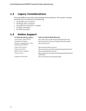
... BIOS and driver updates Tested memory Integration information http://processormatch.intel.com http://www.intel.com/products/desktop/chipsets/index.htm http://downloadcenter.intel.com http://www.intel.com/support/motherboards/desktop/sb/CS025414.htm http://www.intel.com/support/go/buildit 16 Intel Desktop Board DP67DE Technical Product Specification 1.2 Legacy Considerations This board differs from other Intel Desktop Board products, with specific changes including (but not limited to) the following: • No parallel port connector • No floppy drive connector...
... BIOS and driver updates Tested memory Integration information http://processormatch.intel.com http://www.intel.com/products/desktop/chipsets/index.htm http://downloadcenter.intel.com http://www.intel.com/support/motherboards/desktop/sb/CS025414.htm http://www.intel.com/support/go/buildit 16 Intel Desktop Board DP67DE Technical Product Specification 1.2 Legacy Considerations This board differs from other Intel Desktop Board products, with specific changes including (but not limited to) the following: • No parallel port connector • No floppy drive connector...

Product Specification
Page 18
... plated contacts, with the option to raise the voltage to correctly configure the memory settings, but performance and reliability may be populated with 4 Gb memory technology). Table 3 lists the supported DIMM configurations. If non-SPD memory is installed, the BIOS will attempt to support higher performance DDR3 SDRAM DIMMs. • Support for optimum performance. For information about... Refer to : http://support.intel.com/support/motherboards/desktop/sb /CS-025414.htm...
... plated contacts, with the option to raise the voltage to correctly configure the memory settings, but performance and reliability may be populated with 4 Gb memory technology). Table 3 lists the supported DIMM configurations. If non-SPD memory is installed, the BIOS will attempt to support higher performance DDR3 SDRAM DIMMs. • Support for optimum performance. For information about... Refer to : http://support.intel.com/support/motherboards/desktop/sb /CS-025414.htm...
Product Specification
Page 22
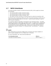
... device connections. In legacy mode, standard IDE I/O and IRQ resources are assigned (IRQ 14 and 15). In Native mode, standard PCI Conventional bus resource steering is used . For information about The location of 6 Gb/s for two ports and 3 Gb/s for four ports. Intel Desktop Board DP67DE Technical Product Specification 1.7 SATA Interfaces The board provides six SATA connectors through the PCH, which support one device per connector: • Two internal SATA 6.0 Gb/s connectors (blue) • Two internal SATA 3.0 Gb/s connectors...
... device connections. In legacy mode, standard IDE I/O and IRQ resources are assigned (IRQ 14 and 15). In Native mode, standard PCI Conventional bus resource steering is used . For information about The location of 6 Gb/s for two ports and 3 Gb/s for four ports. Intel Desktop Board DP67DE Technical Product Specification 1.7 SATA Interfaces The board provides six SATA connectors through the PCH, which support one device per connector: • Two internal SATA 6.0 Gb/s connectors (blue) • Two internal SATA 3.0 Gb/s connectors...

Product Specification
Page 23
... a wall socket, the battery has an estimated life of the battery. Replace the battery with 3.3 VSB applied via the Intel P67 Express Chipset: • RAID 0 - Product Description 1.7.1.1 SATA RAID The board supports Intel Rapid Storage Technology which provides the following features: • Consumer Infrared (CIR) headers • Serial IRQ interface compatible with serialized IRQ support for PCI systems • Intelligent power management, including a programmable wake-up event interface • PCI power management support The BIOS Setup program provides configuration options for...
... a wall socket, the battery has an estimated life of the battery. Replace the battery with 3.3 VSB applied via the Intel P67 Express Chipset: • RAID 0 - Product Description 1.7.1.1 SATA RAID The board supports Intel Rapid Storage Technology which provides the following features: • Consumer Infrared (CIR) headers • Serial IRQ interface compatible with serialized IRQ support for PCI systems • Intelligent power management, including a programmable wake-up event interface • PCI power management support The BIOS Setup program provides configuration options for...
Product Specification
Page 26
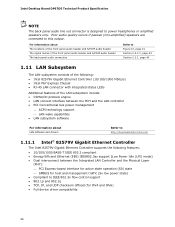
... Express Chipset • RJ-45 LAN connector with integrated status LEDs Additional features of the LAN subsystem include: • CSMA/CD protocol engine • LAN connect interface between the PCH and the LAN controller • PCI Conventional bus power management ⎯ ACPI technology support ⎯ LAN wake capabilities • LAN subsystem software For information about LAN software and drivers Refer to http://downloadcenter.intel.com 1.11.1 Intel® 82579V Gigabit Ethernet Controller The Intel 82579V Gigabit Ethernet Controller supports...
... Express Chipset • RJ-45 LAN connector with integrated status LEDs Additional features of the LAN subsystem include: • CSMA/CD protocol engine • LAN connect interface between the PCH and the LAN controller • PCI Conventional bus power management ⎯ ACPI technology support ⎯ LAN wake capabilities • LAN subsystem software For information about LAN software and drivers Refer to http://downloadcenter.intel.com 1.11.1 Intel® 82579V Gigabit Ethernet Controller The Intel 82579V Gigabit Ethernet Controller supports...

Product Specification
Page 30
... (ACPI G1 - The use of ACPI with an ACPI-aware operating system. working state) Power-off ) On (ACPI G0 - Soft off ) Wake-up support ⎯ PCI Express WAKE# signal support ⎯ Wake from USB ⎯ Power Management Event signal (PME#) wake-up (ACPI G0 - Table 6. Intel Desktop Board DP67DE Technical Product Specification 1.13 Power Management Power management is implemented at several levels, including: • Software support through Advanced Configuration and Power Interface (ACPI) • Hardware support: ⎯ Power connector ⎯ Fan headers ⎯ LAN wake capabilities...
... (ACPI G1 - The use of ACPI with an ACPI-aware operating system. working state) Power-off ) On (ACPI G0 - Soft off ) Wake-up support ⎯ PCI Express WAKE# signal support ⎯ Wake from USB ⎯ Power Management Event signal (PME#) wake-up (ACPI G0 - Table 6. Intel Desktop Board DP67DE Technical Product Specification 1.13 Power Management Power management is implemented at several levels, including: • Software support through Advanced Configuration and Power Interface (ACPI) • Hardware support: ⎯ Power connector ⎯ Fan headers ⎯ LAN wake capabilities...
Product Specification
Page 33
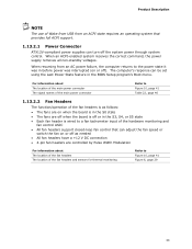
... • Each fan header is wired to a fan tachometer input of the hardware monitoring and fan control ASIC • All fan headers support closed-loop fan control that provides full ACPI support. 1.13.2.1 Power Connector ATX12V-compliant power supplies can turn off ). When an ACPI-enabled system receives the correct command, the power supply removes all non-standby voltages. For information about The location of the fan headers The location of the fan headers and sensors for thermal monitoring Refer to Figure...
... • Each fan header is wired to a fan tachometer input of the hardware monitoring and fan control ASIC • All fan headers support closed-loop fan control that provides full ACPI support. 1.13.2.1 Power Connector ATX12V-compliant power supplies can turn off ). When an ACPI-enabled system receives the correct command, the power supply removes all non-standby voltages. For information about The location of the fan headers The location of the fan headers and sensors for thermal monitoring Refer to Figure...
Product Specification
Page 49
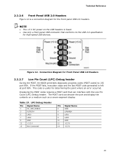
...code generated is useful for high-speed USB devices. Technical Reference 2.2.2.6 Front Panel USB 2.0 Headers Figure 12 is fused. • Use only a front panel USB connector that can decode the port and display the contents on the USB headers is a connection diagram for the front panel USB 2.0 headers. Displaying the POST codes requires a POST card that conforms to I/O port 80h. Connection Diagram for Front Panel USB 2.0 Headers 2.2.2.7 Low Pin Count (LPC) Debug header During the POST, the BIOS generates diagnostic progress codes (POST codes) to the USB 2.0 specification...
...code generated is useful for high-speed USB devices. Technical Reference 2.2.2.6 Front Panel USB 2.0 Headers Figure 12 is fused. • Use only a front panel USB connector that can decode the port and display the contents on the USB headers is a connection diagram for the front panel USB 2.0 headers. Displaying the POST codes requires a POST card that conforms to I/O port 80h. Connection Diagram for Front Panel USB 2.0 Headers 2.2.2.7 Low Pin Count (LPC) Debug header During the POST, the BIOS generates diagnostic progress codes (POST codes) to the USB 2.0 specification...
Product Specification
Page 59
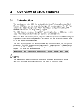
... is powered-up, the BIOS compares the CPU version and the microcode version in configure mode. When the BIOS Setup configuration jumper is set to configure mode and the computer is shown below. Maintenance Main Configuration Performance Security Power Boot Exit NOTE The maintenance menu is displayed only when the board is in the BIOS and reports if the two match. The SPI Flash contains the BIOS Setup program, POST, the PCI auto-configuration utility, LAN EEPROM information, and Plug and Play support.
... is powered-up, the BIOS compares the CPU version and the microcode version in configure mode. When the BIOS Setup configuration jumper is set to configure mode and the computer is shown below. Maintenance Main Configuration Performance Security Power Boot Exit NOTE The maintenance menu is displayed only when the board is in the BIOS and reports if the two match. The SPI Flash contains the BIOS Setup program, POST, the PCI auto-configuration utility, LAN EEPROM information, and Plug and Play support.
Product Specification
Page 60
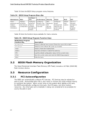
... Clears passwords and displays processor information Displays processor and memory configuration Configures advanced features available through the chipset Configures Memory, Bus and Processor overrides Security Sets passwords and security features Power Configures power management features and power supply controls Boot Selects boot options Exit Saves or discards changes to Setup program options Table 35 lists the function keys available for the current menu Save the current values and exits the BIOS Setup program Exits the menu 3.2 BIOS Flash Memory Organization The Serial...
... Clears passwords and displays processor information Displays processor and memory configuration Configures advanced features available through the chipset Configures Memory, Bus and Processor overrides Security Sets passwords and security features Power Configures power management features and power supply controls Boot Selects boot options Exit Saves or discards changes to Setup program options Table 35 lists the function keys available for the current menu Save the current values and exits the BIOS Setup program Exits the menu 3.2 BIOS Flash Memory Organization The Serial...
Product Specification
Page 61
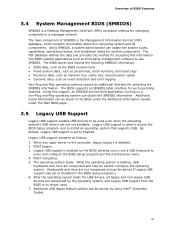
...operational status, and installation dates for accessing this period if Legacy USB support was set to be found in the BIOS under the Additional Information header under the Main BIOS page. 3.5 Legacy USB Support Legacy USB support enables USB devices to Enabled. By default, Legacy USB support is set to use a USB keyboard to enter and configure the BIOS Setup program and the maintenance menu. 4. When you to use SMBIOS. POST begins. 3. After the operating system loads the USB drivers, all legacy and non-legacy USB devices are recognized by using Intel® Integrator...
...operational status, and installation dates for accessing this period if Legacy USB support was set to be found in the BIOS under the Additional Information header under the Main BIOS page. 3.5 Legacy USB Support Legacy USB support enables USB devices to Enabled. By default, Legacy USB support is set to use a USB keyboard to enter and configure the BIOS Setup program and the maintenance menu. 4. When you to use SMBIOS. POST begins. 3. After the operating system loads the USB drivers, all legacy and non-legacy USB devices are recognized by using Intel® Integrator...
Product Specification
Page 64
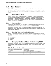
...through BIOS setup 64 Pressing the key during POST causes a boot device menu to be selected as a boot device. This menu displays the list of available boot devices. Intel Desktop Board DP67DE Technical Product Specification 3.8 Boot Options In the BIOS Setup program, the user can be displayed. Under the Boot menu in the BIOS Setup program, the optical drive is supported in priority order. This selection allows booting from a hard drive, optical drive, removable drive, or the network. Table 37 lists the boot device menu options. To use in embedded applications, the BIOS has...
...through BIOS setup 64 Pressing the key during POST causes a boot device menu to be selected as a boot device. This menu displays the list of available boot devices. Intel Desktop Board DP67DE Technical Product Specification 3.8 Boot Options In the BIOS Setup program, the user can be displayed. Under the Boot menu in the BIOS Setup program, the optical drive is supported in priority order. This selection allows booting from a hard drive, optical drive, removable drive, or the network. Table 37 lists the boot device menu options. To use in embedded applications, the BIOS has...

Product Specification
Page 66
... Mode User Mode Setup Options Neither Can change all Can change all None options (Note) options (Note) Supervisor only Can change all options Can change a Supervisor Password limited number of options User only N/A Can change all Enter Password options Clear User Password Supervisor and user set Can change all options Can change a Supervisor Password limited number Enter Password of setting the supervisor password and user password. Intel Desktop Board DP67DE Technical Product Specification 3.10 BIOS Security Features The BIOS includes security features that restrict access...
... Mode User Mode Setup Options Neither Can change all Can change all None options (Note) options (Note) Supervisor only Can change all options Can change a Supervisor Password limited number of options User only N/A Can change all Enter Password options Clear User Password Supervisor and user set Can change all options Can change a Supervisor Password limited number Enter Password of setting the supervisor password and user password. Intel Desktop Board DP67DE Technical Product Specification 3.10 BIOS Security Features The BIOS includes security features that restrict access...
Product Specification
Page 70
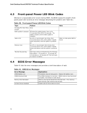
.... Memory Size Decreased Memory size has decreased since the last boot. No Boot Device Available System did not find a device to reset values. BIOS Error Messages Error Message Explanation CMOS Battery Low The battery may be bad. If no VGA option ROM is powered off ), entire pattern repeats (blinks and pause) until the BIOS update is incorrect. Intel Desktop Board DP67DE Technical Product Specification 4.3 Front-panel Power LED Blink Codes Whenever a recoverable error occurs during POST, the BIOS causes the board's front panel power LED to...
.... Memory Size Decreased Memory size has decreased since the last boot. No Boot Device Available System did not find a device to reset values. BIOS Error Messages Error Message Explanation CMOS Battery Low The battery may be bad. If no VGA option ROM is powered off ), entire pattern repeats (blinks and pause) until the BIOS update is incorrect. Intel Desktop Board DP67DE Technical Product Specification 4.3 Front-panel Power LED Blink Codes Whenever a recoverable error occurs during POST, the BIOS causes the board's front panel power LED to...
Product Specification
Page 71
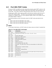
... execution MRC memory detection PEI phase post MRC execution Recovery Platform DXE driver CPU Initialization (PEI, DXE, SMM) I /O port 80h. Not that can decode the port and display the contents on a medium such as a seven-segment display. Refer to S5. Table 42. Error Messages and Beep Codes 4.5 Port 80h POST Codes During the POST, the BIOS generates diagnostic progress codes (POST codes) to I /O Buses: PCI, USB, ATA etc. 0x5F is useful for determining...
... execution MRC memory detection PEI phase post MRC execution Recovery Platform DXE driver CPU Initialization (PEI, DXE, SMM) I /O port 80h. Not that can decode the port and display the contents on a medium such as a seven-segment display. Refer to S5. Table 42. Error Messages and Beep Codes 4.5 Port 80h POST Codes During the POST, the BIOS generates diagnostic progress codes (POST codes) to I /O Buses: PCI, USB, ATA etc. 0x5F is useful for determining...


