
User Manual
Page 5
... 23. Low Voltage HD Audio Rework (Sus Rail 76 Figure 25. Applying the Thermal Grease 80 Figure 27. Step 9 - Back Panel Connectors 51 Figure 4. Step 4 - D-Connector to Component Video Cable 52 Figure 5. Power On and Reset Buttons 57 Figure 9. Plugging in...Figure 26. Step 8 - Appendix C Programming System BIOS Using a Flash Programming Device 77 Appendix D CPU Thermal Solution (Heatsink) Installation 78 Figures Figure 1. Fern Hill Development Board Components 49 Figure 3. Upham IV Interposer Card 70 Figure 20. AUX Pull-Down Rework 66 Figure 17....
... 23. Low Voltage HD Audio Rework (Sus Rail 76 Figure 25. Applying the Thermal Grease 80 Figure 27. Step 9 - Back Panel Connectors 51 Figure 4. Step 4 - D-Connector to Component Video Cable 52 Figure 5. Power On and Reset Buttons 57 Figure 9. Plugging in...Figure 26. Step 8 - Appendix C Programming System BIOS Using a Flash Programming Device 77 Appendix D CPU Thermal Solution (Heatsink) Installation 78 Figures Figure 1. Fern Hill Development Board Components 49 Figure 3. Upham IV Interposer Card 70 Figure 20. AUX Pull-Down Rework 66 Figure 17....

User Manual
Page 8
..., LED functions, and their locations on how to the Intel® CoreTM 2 Duo processor and Intel® GS45 Express Chipset please visit: Processor: http://developer.intel.com/design/intarch/core2duo/tech_docs.htm Chipset: http://www.intel.com/products/embedded/chipsets.htm Content Overview Chapter 1.0, "About...Jumper Settings Table (Table 18) All other components and references are the same between boards. This chapter explains the basics steps necessary to obtain literature and contact customer support. This chapter also includes information on the development board, along with features...
..., LED functions, and their locations on how to the Intel® CoreTM 2 Duo processor and Intel® GS45 Express Chipset please visit: Processor: http://developer.intel.com/design/intarch/core2duo/tech_docs.htm Chipset: http://www.intel.com/products/embedded/chipsets.htm Content Overview Chapter 1.0, "About...Jumper Settings Table (Table 18) All other components and references are the same between boards. This chapter explains the basics steps necessary to obtain literature and contact customer support. This chapter also includes information on the development board, along with features...

User Manual
Page 9
... Thermal Solution (Heatsink) Installation Instructions" - This appendix gives detailed installation instructions for the Intel® CoreTM 2 Duo processor heatsink. 1.2 Text Conventions The notations listed in Table 1 may use of the programming ...headers. You may be used to a signal name indicates that the signal is shown as 0FFH.) Decimal and binary numbers are shown in cards available from Intel that begin with correct values. This appendix provides step by step...
... Thermal Solution (Heatsink) Installation Instructions" - This appendix gives detailed installation instructions for the Intel® CoreTM 2 Duo processor heatsink. 1.2 Text Conventions The notations listed in Table 1 may use of the programming ...headers. You may be used to a signal name indicates that the signal is shown as 0FFH.) Decimal and binary numbers are shown in cards available from Intel that begin with correct values. This appendix provides step by step...
User Manual
Page 21
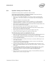
...Intel® AMPS AC to DC power adapter into J1H1 or J1H2. These steps should already be completed by the user: 1. Check these items to ensure that nothing came loose during shipment. • Place one of this document. (Replacing detached 1-x jumpers is not required for the processor... U2E1. • Install the configuration jumpers as shown in Section 4.3.1 of the USB connectors. 3. The following steps to operate the reference board. Connect a monitor to the card. 6. Optionally plug ...
...Intel® AMPS AC to DC power adapter into J1H1 or J1H2. These steps should already be completed by the user: 1. Check these items to ensure that nothing came loose during shipment. • Place one of this document. (Replacing detached 1-x jumpers is not required for the processor... U2E1. • Install the configuration jumpers as shown in Section 4.3.1 of the USB connectors. 3. The following steps to operate the reference board. Connect a monitor to the card. 6. Optionally plug ...

User Manual
Page 24
... bus and are soldered down. Another method is through software utilities as outlined in Section 2.6 above . 2. Record the 12 digit MAC Address of programming these steps to the Bootable USB Device • BIOS Image Files o spifull.bin • BIOS Programming Software Utilities o fpt.exe (DOS SPI Flash Utility) o fparts.txt (helper...
... bus and are soldered down. Another method is through software utilities as outlined in Section 2.6 above . 2. Record the 12 digit MAC Address of programming these steps to the Bootable USB Device • BIOS Image Files o spifull.bin • BIOS Programming Software Utilities o fpt.exe (DOS SPI Flash Utility) o fparts.txt (helper...

User Manual
Page 75
...,R7V8,R7V3,R7V4,R5F7,R9E14,R9E12 ,R9E8 Note: All rework should use lead-free solder in order to keep the board RoHS compliant. Follow the steps below to keep the board RoHS compliant. Unstuff R7H3 and stuff R7H2 Figure 23. Low Voltage HD Audio Rework (Always Rail) Development Kit User's Manual...
...,R7V8,R7V3,R7V4,R5F7,R9E14,R9E12 ,R9E8 Note: All rework should use lead-free solder in order to keep the board RoHS compliant. Follow the steps below to keep the board RoHS compliant. Unstuff R7H3 and stuff R7H2 Figure 23. Low Voltage HD Audio Rework (Always Rail) Development Kit User's Manual...

User Manual
Page 79
... on the underside of the development board so that the pins protrude through the holes in the development board around the processor. (See the figure below.) Be sure to the processor. Development Kit User's Manual 79 Clean the die of the die is attached to orient the backplate so that the surface...
... on the underside of the development board so that the pins protrude through the holes in the development board around the processor. (See the figure below.) Be sure to the processor. Development Kit User's Manual 79 Clean the die of the die is attached to orient the backplate so that the surface...

User Manual
Page 80
Applying the Thermal Grease 80 Development Kit User's Manual Step 6 - CPU Thermal Solution (Heatsink) Installation 6. Remove the tube of thermal grease from the package and use it to coat the exposed die of the CPU with the thermal grease. (See the figure below) Figure 26.
Applying the Thermal Grease 80 Development Kit User's Manual Step 6 - CPU Thermal Solution (Heatsink) Installation 6. Remove the tube of thermal grease from the package and use it to coat the exposed die of the CPU with the thermal grease. (See the figure below) Figure 26.

User Manual
Page 81
Squeezing Activation Arm Development Kit User's Manual 81 Step 7 - This will cause the springs on the heatsink attachment mechanism to the heatsink base. CPU Thermal Solution (Heatsink) Installation 7. Pick up the heatsink and squeeze the activation arm until it comes in contact with the base plate that is attached to compress. (See the figure below) Figure 27.
Squeezing Activation Arm Development Kit User's Manual 81 Step 7 - This will cause the springs on the heatsink attachment mechanism to the heatsink base. CPU Thermal Solution (Heatsink) Installation 7. Pick up the heatsink and squeeze the activation arm until it comes in contact with the base plate that is attached to compress. (See the figure below) Figure 27.

User Manual
Page 82
While keeping the activation arm compressed, place the heatsink over the processor die and the pins on the backplate have inserted into the base of the heatsink.... Development Kit User's Manual Slowly let go of the activation arm until the lugs have travelled the entire length of the processor die. Figure 28. CPU Thermal Solution (Heatsink) Installation 8. Slide the heatsink over the lugs on top of the channel...that the base is directly over the pins of the heatsink makes contact with the processor die. Step 8 - Lower the heatsink until the base of the heatsink backplate.
While keeping the activation arm compressed, place the heatsink over the processor die and the pins on the backplate have inserted into the base of the heatsink.... Development Kit User's Manual Slowly let go of the activation arm until the lugs have travelled the entire length of the processor die. Figure 28. CPU Thermal Solution (Heatsink) Installation 8. Slide the heatsink over the lugs on top of the channel...that the base is directly over the pins of the heatsink makes contact with the processor die. Step 8 - Lower the heatsink until the base of the heatsink backplate.
User Manual
Page 83
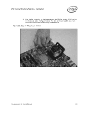
Figure 29. Plug the fan connector for the heatsink onto the CPU fan header (J2B3) on the motherboard. (See the figure below) The CPU fan header (J2B3) is a 3-pin connector with the words CPU Fan printed beside it. Plugging in the Fan Development Kit User's Manual 83 Step 9 - CPU Thermal Solution (Heatsink) Installation 9.
Figure 29. Plug the fan connector for the heatsink onto the CPU fan header (J2B3) on the motherboard. (See the figure below) The CPU fan header (J2B3) is a 3-pin connector with the words CPU Fan printed beside it. Plugging in the Fan Development Kit User's Manual 83 Step 9 - CPU Thermal Solution (Heatsink) Installation 9.

User Manual
Page 84
Step 10 - CPU Thermal Solution (Heatsink) Installation 10. Figure 30. Completed Assembly § 84 Development Kit User's Manual Once the thermal solution is in-place, the development kit is ready to use.
Step 10 - CPU Thermal Solution (Heatsink) Installation 10. Figure 30. Completed Assembly § 84 Development Kit User's Manual Once the thermal solution is in-place, the development kit is ready to use.