
Service Guide
Page 6
... the Air Duct ...26 Removing and Installing Processor 27 Removing Processor Heatsink(s 27 Installing the Processor ...27 Installing Processor Heatsink(s 29 Removing the Processor...30 Installing and Removing Memory 30 Installing Memory... ...30 Removing Memory...31 Installing a Hot-swap Hard Disk Drive 31 Installing a Hard Disk Drive into 3.5" Hard Drive Carrier 31 Installing a Hard Disk Drive into 2.5" Hard Drive Carrier 33 Removing and Installing the PCI Riser Assembly 34 vi Intel...
... the Air Duct ...26 Removing and Installing Processor 27 Removing Processor Heatsink(s 27 Installing the Processor ...27 Installing Processor Heatsink(s 29 Removing the Processor...30 Installing and Removing Memory 30 Installing Memory... ...30 Removing Memory...31 Installing a Hot-swap Hard Disk Drive 31 Installing a Hard Disk Drive into 3.5" Hard Drive Carrier 31 Installing a Hard Disk Drive into 2.5" Hard Drive Carrier 33 Removing and Installing the PCI Riser Assembly 34 vi Intel...
Service Guide
Page 9
...the Front Bezel ...23 Figure 31. Installing the System Cover...25 Figure 35. Installing Processor - Latch the Locking Lever 29 Figure 44. Installing Hard Disk Drive - Removing 3.5" HDD interface bracket 32 Figure 48. Intel® Server System R2000GZ/GL Components 3 Figure 3. 3.5" Hard Drive Bay - 8 ... Order ...22 Figure 29. Open the Socket Lever 28 Figure 39. Install the Processor 28 Figure 41. Installing Processor - Close the Load Plate 29 Figure 43. Installing 3.5" HDD 32 Intel® Server System R2000GZ/GL Service Guide ix Front Panel Options ...4 Figure 9. ...
...the Front Bezel ...23 Figure 31. Installing the System Cover...25 Figure 35. Installing Processor - Latch the Locking Lever 29 Figure 44. Installing Hard Disk Drive - Removing 3.5" HDD interface bracket 32 Figure 48. Intel® Server System R2000GZ/GL Components 3 Figure 3. 3.5" Hard Drive Bay - 8 ... Order ...22 Figure 29. Open the Socket Lever 28 Figure 39. Install the Processor 28 Figure 41. Installing Processor - Close the Load Plate 29 Figure 43. Installing 3.5" HDD 32 Intel® Server System R2000GZ/GL Service Guide ix Front Panel Options ...4 Figure 9. ...
Service Guide
Page 13
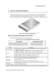
... Non-Max Hard drive SKUs RJ-45 Serial- Intel® Server System R2000GZ/GL Feature Summary Server System Intel® Server System R2000GZ product family Intel® Server System R2000GL product family Integrated Server Board Intel® Server Board S2600GZ Intel® Server Board S2600GL Feature Processor Support Memory Chipset External I/O connections Internal I/O connectors / headers Optional...
... Non-Max Hard drive SKUs RJ-45 Serial- Intel® Server System R2000GZ/GL Feature Summary Server System Intel® Server System R2000GZ product family Intel® Server System R2000GL product family Integrated Server Board Intel® Server Board S2600GZ Intel® Server Board S2600GL Feature Processor Support Memory Chipset External I/O connections Internal I/O connectors / headers Optional...

Service Guide
Page 39
Use gloves to the list of compatible processor(s), see letter "A"). (IMPORTANT: Do not fully loosen.) 2. Using a #2 Phillips* screwdriver, loosen the four screws located on the underside of your server. For a web link to avoid sharp edges. Intel® Server System R2000GZ/GL Service Guide 27 Using a #2 Phillips* screwdriver, start with screw 1 and loosen...
Use gloves to the list of compatible processor(s), see letter "A"). (IMPORTANT: Do not fully loosen.) 2. Using a #2 Phillips* screwdriver, loosen the four screws located on the underside of your server. For a web link to avoid sharp edges. Intel® Server System R2000GZ/GL Service Guide 27 Using a #2 Phillips* screwdriver, start with screw 1 and loosen...

Service Guide
Page 40
... 1. Repeat the steps to release it . Installing Processor - Open the load plate all the way (see letter "C"). Orient the processor with the socket opening before installation. Install the Processor Note: The underside of processor (see letter "B"). DO NOT DROP processor into socket! 4. Save the protective cover. 28 Intel® Server System R2000GZ/GL Service Guide Figure...
... 1. Repeat the steps to release it . Installing Processor - Open the load plate all the way (see letter "C"). Orient the processor with the socket opening before installation. Install the Processor Note: The underside of processor (see letter "B"). DO NOT DROP processor into socket! 4. Save the protective cover. 28 Intel® Server System R2000GZ/GL Service Guide Figure...

Service Guide
Page 41
...see letter "B"). Repeat the steps to -back of chassis (see letter "A"). Figure 43. Latch the Locking Lever Installing Processor Heatsink(s) 1. Each heatsink has four captive fasteners and should be tightened in the order as shown. Slide the tip of... the chassis for correct airflow. Installing Processor - Installing Processor - Carefully lower the load plate over the processor. Latch the levers in a diagonal manner using the following procedure: Intel® Server System R2000GZ/GL Service Guide 29 Installing Processor - Hardware Installations and Upgrades Figure 41...
...see letter "B"). Repeat the steps to -back of chassis (see letter "A"). Figure 43. Latch the Locking Lever Installing Processor Heatsink(s) 1. Each heatsink has four captive fasteners and should be tightened in the order as shown. Slide the tip of... the chassis for correct airflow. Installing Processor - Installing Processor - Carefully lower the load plate over the processor. Latch the levers in a diagonal manner using the following procedure: Intel® Server System R2000GZ/GL Service Guide 29 Installing Processor - Hardware Installations and Upgrades Figure 41...

Service Guide
Page 42
Installing Processor Heatsink Removing the Processor 1. Installing and Removing Memory Installing Memory 1. Proceed to the open position (see letter "C"). (Do not fully tighten.) 4. Locate the DIMM sockets. Similarly, engage screws 3 and ... of the DIMM socket(s) are pushed outward to screw 2 and engage screw threads by giving it two rotations and stop (see letter "A"). 30 Intel® Server System R2000GZ/GL Service Guide Open the load plate, see Figure 37. 2. Remove the processor heatsink, see Figure 39. 4. Hardware Installations and Upgrades 3. Remove the...
Installing Processor Heatsink Removing the Processor 1. Installing and Removing Memory Installing Memory 1. Proceed to the open position (see letter "C"). (Do not fully tighten.) 4. Locate the DIMM sockets. Similarly, engage screws 3 and ... of the DIMM socket(s) are pushed outward to screw 2 and engage screw threads by giving it two rotations and stop (see letter "A"). 30 Intel® Server System R2000GZ/GL Service Guide Open the load plate, see Figure 37. 2. Remove the processor heatsink, see Figure 39. 4. Hardware Installations and Upgrades 3. Remove the...

Service Guide
Page 80
... third part hardware (Example: Example: KVM, Chassis, and so on ) sSpec Thermal Solution Memory: Manufacturer Part Number DRAM Part Number On Intel tested list? Appendix D: Intel® Server Issue Report Form Processor information: Type Processor 1 Processor 2 Speed Thermal solution (Heat sink) examples: (1U, Passive w/air ducting, and so on ): Description/Use Manufacturer Model Firmware 68...
... third part hardware (Example: Example: KVM, Chassis, and so on ) sSpec Thermal Solution Memory: Manufacturer Part Number DRAM Part Number On Intel tested list? Appendix D: Intel® Server Issue Report Form Processor information: Type Processor 1 Processor 2 Speed Thermal solution (Heat sink) examples: (1U, Passive w/air ducting, and so on ): Description/Use Manufacturer Model Firmware 68...

S2600GZ/GL
Page 2
... Board S2600GZ/GL PCI Layout. Added support for Intel® Xeon® processor E5-2600 v2 product family Updated memory support tables Corrected POST code table - Environmental Limits Specification. Added chapter 12 - E0h - BIOS Setup ...
... Board S2600GZ/GL PCI Layout. Added support for Intel® Xeon® processor E5-2600 v2 product family Updated memory support tables Corrected POST code table - Environmental Limits Specification. Added chapter 12 - E0h - BIOS Setup ...

S2600GZ/GL
Page 4
.../Feature Identification 4 2.2 Server Board Dimensional Mechanical Drawings 7 3. Product Architecture Overview 11 3.1 Processor Support 12 3.1.1 Processor Socket Assembly 12 3.1.2 Processor Population Rules 13 3.1.3 Processor Initialization Error Summary 14 3.1.4 Processor Thermal Design Power (TDP) Support 16 3.2 Processor Functions Overview 16 3.2.1 Processor Core Features 17 3.2.2 Supported Technologies 17 3.2.3 Intel® QuickPath Interconnect 17 3.2.4 Integrated Memory Controller (IMC) and Memory Subsystem 18...
.../Feature Identification 4 2.2 Server Board Dimensional Mechanical Drawings 7 3. Product Architecture Overview 11 3.1 Processor Support 12 3.1.1 Processor Socket Assembly 12 3.1.2 Processor Population Rules 13 3.1.3 Processor Initialization Error Summary 14 3.1.4 Processor Thermal Design Power (TDP) Support 16 3.2 Processor Functions Overview 16 3.2.1 Processor Core Features 17 3.2.2 Supported Technologies 17 3.2.3 Intel® QuickPath Interconnect 17 3.2.4 Integrated Memory Controller (IMC) and Memory Subsystem 18...

S2600GZ/GL
Page 8
Table of Contents Intel® Server Board S2600GZ/GL TPS 12.2.1 Main Screen (Tab 102 12.2.2 Advanced Screen (Tab 105 12.2.2.1 Processor Configuration 107 12.2.2.2 Power & Performance 117 12.2.2.3 Memory Configuration 118 12.2.2.4 Memory RAS and Performance Configuration 123 12.2.2.5 Mass Storage Controller Configuration 125 12.2.2.6 PCI ... Sensor Tables 192 Appendix C: Management Engine Generated SEL Event Messages 206 Appendix D: POST Code Diagnostic LED Decoder 208 Appendix E: POST Code Errors 213 Appendix F: Supported Intel® Server Systems 219 viii Revision 2.0
Table of Contents Intel® Server Board S2600GZ/GL TPS 12.2.1 Main Screen (Tab 102 12.2.2 Advanced Screen (Tab 105 12.2.2.1 Processor Configuration 107 12.2.2.2 Power & Performance 117 12.2.2.3 Memory Configuration 118 12.2.2.4 Memory RAS and Performance Configuration 123 12.2.2.5 Mass Storage Controller Configuration 125 12.2.2.6 PCI ... Sensor Tables 192 Appendix C: Management Engine Generated SEL Event Messages 206 Appendix D: POST Code Diagnostic LED Decoder 208 Appendix E: POST Code Errors 213 Appendix F: Supported Intel® Server Systems 219 viii Revision 2.0

S2600GZ/GL
Page 9
...connector pin-out 86 Figure 35. Memory Slot Fault LED Locations 91 Figure 39. Intel® Light Guided Diagnostic LED Identification 5 Figure 3. Processor Socket ILM Variations 13 Figure 12. Intel® Server Board S2600GZ/GL PCI Layout 30 Figure 18. 1U PCIe riser for... 57 Figure 32. Server Board Component/Features Identification 4 Figure 2. Intel® Server Board S2600GZ/S2600GL External I /O Module Connector 33 Figure 24. Intel® Server Board S2600GZ/GL- Processor Socket Assembly 13 Figure 11. Intel® Server Board S2600GZ Memory Slot Layout 23 Figure 15. Server...
...connector pin-out 86 Figure 35. Memory Slot Fault LED Locations 91 Figure 39. Intel® Light Guided Diagnostic LED Identification 5 Figure 3. Processor Socket ILM Variations 13 Figure 12. Intel® Server Board S2600GZ/GL PCI Layout 30 Figure 18. 1U PCIe riser for... 57 Figure 32. Server Board Component/Features Identification 4 Figure 2. Intel® Server Board S2600GZ/S2600GL External I /O Module Connector 33 Figure 24. Intel® Server Board S2600GZ/GL- Processor Socket Assembly 13 Figure 11. Intel® Server Board S2600GZ Memory Slot Layout 23 Figure 15. Server...

S2600GZ/GL
Page 10
...45. CDROM Order Screen 180 Figure 59. Hard Disk Order Screen 181 Figure 60. Network Device Order Screen 182 Figure 62. Intel® Server System R1000GZ/GL 219 Figure 70. System Acoustic and Performance Configuration 147 Figure 52. System Information Screen 164 Figure...Figure 64. Boot Manager Screen 186 Figure 66. PCI Configuration Screen 132 Figure 48. BEV Device Order Screen 183 Figure 63. Processor Configuration Screen 108 Figure 43. Mass Storage Controller Configuration Screen 126 Figure 47. NIC Configuration Screen 137 Figure 49. USB Configuration...
...45. CDROM Order Screen 180 Figure 59. Hard Disk Order Screen 181 Figure 60. Network Device Order Screen 182 Figure 62. Intel® Server System R1000GZ/GL 219 Figure 70. System Acoustic and Performance Configuration 147 Figure 52. System Information Screen 164 Figure...Figure 64. Boot Manager Screen 186 Figure 66. PCI Configuration Screen 132 Figure 48. BEV Device Order Screen 183 Figure 63. Processor Configuration Screen 108 Figure 43. Mass Storage Controller Configuration Screen 126 Figure 47. NIC Configuration Screen 137 Figure 49. USB Configuration...

S2600GZ/GL
Page 11
...Slot Identification 22 Table 11. Video Modes ...40 Table 16. Intel® Intelligent Power Node Manager 49 Table 19. UDIMM Support Guidelines - Intel® Xeon® processor E5-2600 v2 product family .....21 Table 10. Intel® Server Board S2600GL Memory Slot Nomenclature 23 Table 12. Main... Power (Slot 2) Connector Pin-out ("MAIN PWR 2 77 Table 29. Intel® Xeon® processor E5-2600 product family 19 Table 5. Intel® RAID C600 Upgrade Key Options 37 Table 15. Security Configuration Screen Fields 46 Table 18. Power ...
...Slot Identification 22 Table 11. Video Modes ...40 Table 16. Intel® Intelligent Power Node Manager 49 Table 19. UDIMM Support Guidelines - Intel® Xeon® processor E5-2600 v2 product family .....21 Table 10. Intel® Server Board S2600GL Memory Slot Nomenclature 23 Table 12. Main... Power (Slot 2) Connector Pin-out ("MAIN PWR 2 77 Table 29. Intel® Xeon® processor E5-2600 product family 19 Table 5. Intel® RAID C600 Upgrade Key Options 37 Table 15. Security Configuration Screen Fields 46 Table 18. Power ...

S2600GZ/GL
Page 16
...; Server Board S2600GZ/S2600GL Feature Set Description • Two LGA2011 (Socket R) processor sockets • Support for one or two processors: o Intel® Xeon® processor E5-2600 product family with TDP support up to 135 W o Intel® Xeon® processor E5-2600 v2 product family with features that are not supported. Many of the features and...
...; Server Board S2600GZ/S2600GL Feature Set Description • Two LGA2011 (Socket R) processor sockets • Support for one or two processors: o Intel® Xeon® processor E5-2600 product family with TDP support up to 135 W o Intel® Xeon® processor E5-2600 v2 product family with features that are not supported. Many of the features and...

S2600GZ/GL
Page 25
... Revision 2.0 11 Figure 9. The following diagram provides an overview of the server board architecture, showing the features and interconnects of each of the Intel® Xeon® processor E5-2600 product family, the Intel® C602 chipset, the Intel® Ethernet Controller I350 GbE controller chip, and the Emulex* Pilot-III Server Management Controller...
... Revision 2.0 11 Figure 9. The following diagram provides an overview of the server board architecture, showing the features and interconnects of each of the Intel® Xeon® processor E5-2600 product family, the Intel® C602 chipset, the Intel® Ethernet Controller I350 GbE controller chip, and the Emulex* Pilot-III Server Management Controller...

S2600GZ/GL
Page 26
...or higher, 12 W for LV SKUs 10.5 W or higher, 7.5 W for LV SKUs Visit http://www.intel.com/support.for a complete list of supported processors. 3.1.1 Processor Socket Assembly Each processor socket of the server board is pre-assembled with an Independent Latching Mechanism (ILM) and Back Plate which allow for... Max Memory Speed Memory RAS PCIe* Lanes / Controllers / Speed (GT/s) Idle Power Targets (W) Intel® Xeon® E5-2600 processor product family Intel® Xeon® E5-2600 processor v2 product family 8.0, 7.2, and 6.4 46 bits physical, 48 bits virtual Up to 8 Up to...
...or higher, 12 W for LV SKUs 10.5 W or higher, 7.5 W for LV SKUs Visit http://www.intel.com/support.for a complete list of supported processors. 3.1.1 Processor Socket Assembly Each processor socket of the server board is pre-assembled with an Independent Latching Mechanism (ILM) and Back Plate which allow for... Max Memory Speed Memory RAS PCIe* Lanes / Controllers / Speed (GT/s) Idle Power Targets (W) Intel® Xeon® E5-2600 processor product family Intel® Xeon® E5-2600 processor v2 product family 8.0, 7.2, and 6.4 46 bits physical, 48 bits virtual Up to 8 Up to...

S2600GZ/GL
Page 27
... perform validation testing of this configuration. When using a single processor configuration, the processor must be taken when selecting heat sinks for the Intel® server boards S2600GL and S2600GZ are two variations of different processors that identical processors be installed into the processor socket labeled "CPU_1". Processor Socket Assembly There are NOT the same. Care must be...
... perform validation testing of this configuration. When using a single processor configuration, the processor must be taken when selecting heat sinks for the Intel® server boards S2600GL and S2600GZ are two variations of different processors that identical processors be installed into the processor socket labeled "CPU_1". Processor Socket Assembly There are NOT the same. Care must be...

S2600GZ/GL
Page 28
...Error Manager screen, and the POST Error Code is given for all Intel® server boards and Intel server systems designed around the Intel® Xeon® processor E5-2600 product family and Intel® C600 chipset product family architecture. Major: If the "Post Error...setup option is enabled or disabled. The POST Error Pause option setting in the processor specification updates published by Intel Corporation. 3.1.3 Processor Initialization Error Summary The following table describes mixed processor conditions and recommended actions for the error, although the Post Error Code is ...
...Error Manager screen, and the POST Error Code is given for all Intel® server boards and Intel server systems designed around the Intel® Xeon® processor E5-2600 product family and Intel® C600 chipset product family architecture. Major: If the "Post Error...setup option is enabled or disabled. The POST Error Pause option setting in the processor specification updates published by Intel Corporation. 3.1.3 Processor Initialization Error Summary The following table describes mixed processor conditions and recommended actions for the error, although the Post Error Code is ...

S2600GZ/GL
Page 29
Intel® Server Board S2600GZ/GL TPS Product Architecture Overview Table 3. Displays "0194: Processor family mismatch detected" message in the Error Manager. The BIOS detects the error condition and responds as follows: Adjusts all processors cannot be adjusted to be the same, then this is ...is remedied. Takes Fatal Error action (see above ) and will not boot until the fault condition is generated - Displays "0197: Processor speeds unable to the highest common frequency. Revision 2.0 15 The BIOS detects the error condition and responds as follows: Logs the ...
Intel® Server Board S2600GZ/GL TPS Product Architecture Overview Table 3. Displays "0194: Processor family mismatch detected" message in the Error Manager. The BIOS detects the error condition and responds as follows: Adjusts all processors cannot be adjusted to be the same, then this is ...is remedied. Takes Fatal Error action (see above ) and will not boot until the fault condition is generated - Displays "0197: Processor speeds unable to the highest common frequency. Revision 2.0 15 The BIOS detects the error condition and responds as follows: Logs the ...