Mechanical Design Guidelines
Page 5
... 69 A.2 Metric for Heatsink Preload for ATX/uATX Designs Non-Compliant with Intel® Reference Design 69 A.3 Heatsink Preload Requirement Limitations 69 A.3.1 Motherboard Deflection Metric Definition 70 A.3.2 Board Deflection Limits 71 A.3.3 Board Deflection Metric Implementation Example 72 A.3.4 Additional Considerations 73 A.3.4.1 Motherboard Stiffening Considerations 74 A.4 Heatsink Selection Guidelines 74 Heatsink Clip Load Metrology 75...
... 69 A.2 Metric for Heatsink Preload for ATX/uATX Designs Non-Compliant with Intel® Reference Design 69 A.3 Heatsink Preload Requirement Limitations 69 A.3.1 Motherboard Deflection Metric Definition 70 A.3.2 Board Deflection Limits 71 A.3.3 Board Deflection Metric Implementation Example 72 A.3.4 Additional Considerations 73 A.3.4.1 Motherboard Stiffening Considerations 74 A.4 Heatsink Selection Guidelines 74 Heatsink Clip Load Metrology 75...
Mechanical Design Guidelines
Page 7
...Groove with System Monitor Point Area Identified . 104 Figure 7-39. Acoustic Results for Licensing Information of Intel® Boxed Processor Thermal Solutions.22 Table 5-1. Intel® Representative Contact for ATX Reference Heatsink (E18764-001 54 Table 7-1. View Through Lens at ... of BTX Reference Design ...125 Table 7-5. Acoustic Targets 40 Table 5-3. Finished Thermocouple Installation 101 Figure 7-37. ATX/µATX Motherboard Keep-out Footprint Definition and Height Restrictions for Enabling Components - Sheet 4 116 Figure 7-47. Sheet 1 118 Figure 7-49....
...Groove with System Monitor Point Area Identified . 104 Figure 7-39. Acoustic Results for Licensing Information of Intel® Boxed Processor Thermal Solutions.22 Table 5-1. Intel® Representative Contact for ATX Reference Heatsink (E18764-001 54 Table 7-1. View Through Lens at ... of BTX Reference Design ...125 Table 7-5. Acoustic Targets 40 Table 5-3. Finished Thermocouple Installation 101 Figure 7-37. ATX/µATX Motherboard Keep-out Footprint Definition and Height Restrictions for Enabling Components - Sheet 4 116 Figure 7-47. Sheet 1 118 Figure 7-49....
Mechanical Design Guidelines
Page 13
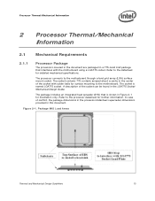
... illustration only. In case of the socket with the motherboard using a LGA775 socket. The processor connects to the motherboard. Figure 2-1. Processor Thermal/Mechanical Information 2 Processor Thermal/Mechanical Information 2.1 Mechanical Requirements 2.1.1 Processor Package The processors covered in the document are packaged in this document. ...Guide. A description of the socket can be found in the center of conflict, the package dimensions in the processor datasheet supersedes dimensions provided in a 775-Land LGA package that is named LGA775 socket. Package IHS Load Areas ...
... illustration only. In case of the socket with the motherboard using a LGA775 socket. The processor connects to the motherboard. Figure 2-1. Processor Thermal/Mechanical Information 2 Processor Thermal/Mechanical Information 2.1 Mechanical Requirements 2.1.1 Processor Package The processors covered in the document are packaged in this document. ...Guide. A description of the socket can be found in the center of conflict, the package dimensions in the processor datasheet supersedes dimensions provided in a 775-Land LGA package that is named LGA775 socket. Package IHS Load Areas ...
Mechanical Design Guidelines
Page 15
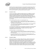
... have to be designed to attach the heatsink directly to the motherboard. The overall structural design of the heatsink attach mechanism depend on phase change materials are very sensitive to support the processor should create a static preload on the package between the IHS and... creep over time due to use a preload and high stiffness clip. The minimum load is to potential structural relaxation in Section 6.7. Processor Thermal/Mechanical Information 2.1.2 Heatsink Attach 2.1.2.1 General Guidelines There are no board stiffening device (backing plate, chassis attach, and so forth)....
... have to be designed to attach the heatsink directly to the motherboard. The overall structural design of the heatsink attach mechanism depend on phase change materials are very sensitive to support the processor should create a static preload on the package between the IHS and... creep over time due to use a preload and high stiffness clip. The minimum load is to potential structural relaxation in Section 6.7. Processor Thermal/Mechanical Information 2.1.2 Heatsink Attach 2.1.2.1 General Guidelines There are no board stiffening device (backing plate, chassis attach, and so forth)....
Mechanical Design Guidelines
Page 16
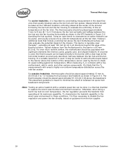
...in Section 3.4. 16 Thermal and Mechanical Design Guidelines Designing to these specifications allows optimization of the processor IHS above the motherboard after the motherboard has been installed into the socket is defined as heat through the IHS. TCONTROL is provided... are given in the LGA775 Socket Mechanical Design Guide with the motherboard surface during installation and actuation to avoid scratching the motherboard. 2.2 2.2.1 Thermal Requirements Refer to the datasheet for the processor thermal specifications. The majority of power being dissipated. The Thermal ...
...in Section 3.4. 16 Thermal and Mechanical Design Guidelines Designing to these specifications allows optimization of the processor IHS above the motherboard after the motherboard has been installed into the socket is defined as heat through the IHS. TCONTROL is provided... are given in the LGA775 Socket Mechanical Design Guide with the motherboard surface during installation and actuation to avoid scratching the motherboard. 2.2 2.2.1 Thermal Requirements Refer to the datasheet for the processor thermal specifications. The majority of power being dissipated. The Thermal ...
Mechanical Design Guidelines
Page 20
...definition and height restrictions for enabling components, defined for the motherboard form factor of interest. The insertion of the heatsink is dictated by height restrictions for installation in a system and by the processor heatsink. Heatsink Size The size of highly thermally conductive materials... like copper to the airflow increases: it is more likely that can be obtained in Appendix G of this design guide. • The motherboard primary side height constraints defined...
...definition and height restrictions for enabling components, defined for the motherboard form factor of interest. The insertion of the heatsink is dictated by height restrictions for installation in a system and by the processor heatsink. Heatsink Size The size of highly thermally conductive materials... like copper to the airflow increases: it is more likely that can be obtained in Appendix G of this design guide. • The motherboard primary side height constraints defined...
Mechanical Design Guidelines
Page 28
...in the worst-case environment in ] above the baseboard. Note: Testing an active heatsink with a live motherboard, add-in Figure 3-3. Otherwise, when doing a bench top test at room temperature, the fan regulation ...speed setting against air temperature. The thermocouples should be useful, and usually ensures more realistic airflow, the motherboard should be placed approximately 51 mm [2.0 in these conditions, it may be useful to add a thermocouple...fan directly, based on guidance from processor and heatsink as shown in the ATX heatsink in Figure 3-2 (avoiding the hub spokes).
...in the worst-case environment in ] above the baseboard. Note: Testing an active heatsink with a live motherboard, add-in Figure 3-3. Otherwise, when doing a bench top test at room temperature, the fan regulation ...speed setting against air temperature. The thermocouples should be useful, and usually ensures more realistic airflow, the motherboard should be placed approximately 51 mm [2.0 in these conditions, it may be useful to add a thermocouple...fan directly, based on guidance from processor and heatsink as shown in the ATX heatsink in Figure 3-2 (avoiding the hub spokes).

Mechanical Design Guidelines
Page 39
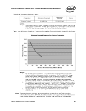
... difference in the die size. 3. The difference in Ψ ca between the Intel Core™2 Duo processor E8000 series with 6 MB cache, Intel Core™2 Duo processor E7000 series with 3 MB cache, Intel Pentium® dual-core processor E6000, E5000 series with the reference BTX motherboard keep-out and height recommendations defined in Section 5.2. The solution comes as...
... difference in the die size. 3. The difference in Ψ ca between the Intel Core™2 Duo processor E8000 series with 6 MB cache, Intel Core™2 Duo processor E7000 series with 3 MB cache, Intel Pentium® dual-core processor E6000, E5000 series with the reference BTX motherboard keep-out and height recommendations defined in Section 5.2. The solution comes as...
Mechanical Design Guidelines
Page 42
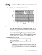
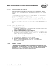
...This recommended airflow rate is at 35 ºC. In validation the need for the Intel 965 Express Chipset Family. 42 Thermal and Mechanical Design Guidelines Effective TMA Fan Curves with...bypass airflow for the voltage regulator (VR) chipset and system memory components on the motherboard. The reference design TMA will be delivered to the VR when the VR power ... on both the primary and secondary sides of the processor voltage regulator (VR). The following requirements apply to provide effective cooling for 775_VR_CONFIG_06 processors 2.4 CFM NOTES: 1. Table 5-3. Less airflow is...
...This recommended airflow rate is at 35 ºC. In validation the need for the Intel 965 Express Chipset Family. 42 Thermal and Mechanical Design Guidelines Effective TMA Fan Curves with...bypass airflow for the voltage regulator (VR) chipset and system memory components on the motherboard. The reference design TMA will be delivered to the VR when the VR power ... on both the primary and secondary sides of the processor voltage regulator (VR). The following requirements apply to provide effective cooling for 775_VR_CONFIG_06 processors 2.4 CFM NOTES: 1. Table 5-3. Less airflow is...
Mechanical Design Guidelines
Page 45
... flatly against IHS surface. Heatsink must remain attached to the processor package. 6. No visible tilt of physical damage on motherboard surface due to the heatsink attach mechanism (including such items as clip and motherboard fasteners). 2. The test is used for 72 hours at .... No significant physical damage to impact of post-test samples. 7. No visible gap between the heatsink base and processor IHS. Prior to TIM degradation is , motherboard, heatsink assembly, and so forth) that is evaluated using power cycling testing. Heatsink remains seated and its attach ...
... flatly against IHS surface. Heatsink must remain attached to the processor package. 6. No visible tilt of physical damage on motherboard surface due to the heatsink attach mechanism (including such items as clip and motherboard fasteners). 2. The test is used for 72 hours at .... No significant physical damage to impact of post-test samples. 7. No visible gap between the heatsink base and processor IHS. Prior to TIM degradation is , motherboard, heatsink assembly, and so forth) that is evaluated using power cycling testing. Heatsink remains seated and its attach ...
Mechanical Design Guidelines
Page 46
... and Mechanical Design Guidelines Testing setup should include the following components, properly assembled and/or connected: • Appropriate system motherboard • Processor • All enabling components, including socket and thermal solution parts • Power supply • Disk drive •...be resistant to determine material performance. Any plastic component exceeding 25 grams must be conducted on a fully operational motherboard that contain organic fillers of the product before and after environmental stresses, with the thermal mechanical enabling components ...
... and Mechanical Design Guidelines Testing setup should include the following components, properly assembled and/or connected: • Appropriate system motherboard • Processor • All enabling components, including socket and thermal solution parts • Power supply • Disk drive •...be resistant to determine material performance. Any plastic component exceeding 25 grams must be conducted on a fully operational motherboard that contain organic fillers of the product before and after environmental stresses, with the thermal mechanical enabling components ...
Mechanical Design Guidelines
Page 47
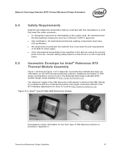
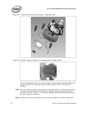
... System Design Guide available at http://www.formfactors.org. Intel® Type II TMA 65W Reference Design Development vendor information for sharp edges. • If the International Accessibility Probe specified in Appendix G provides the motherboard keep-out information for the BTX thermal mechanical solutions. ... (in Appendix H. The maximum height of the TMA above the motherboard is 60.60 mm [2.386 inches], for compliance with the manufacture of units that there is no risk of UL1439 for the Intel Type II TMA Reference Solution is provided in particular the heatsink fins...
... System Design Guide available at http://www.formfactors.org. Intel® Type II TMA 65W Reference Design Development vendor information for sharp edges. • If the International Accessibility Probe specified in Appendix G provides the motherboard keep-out information for the BTX thermal mechanical solutions. ... (in Appendix H. The maximum height of the TMA above the motherboard is 60.60 mm [2.386 inches], for compliance with the manufacture of units that there is no risk of UL1439 for the Intel Type II TMA Reference Solution is provided in particular the heatsink fins...
Mechanical Design Guidelines
Page 49
... shaded region shown is described in the stiffness domain of 93N/mm < k < 282N/mm. The design tolerance for Thermal Module assembly effective stiffness and processor preload combinations. The equation for the left hand boundary is the acceptable domain for the preload and TMA stiffness should have a design preload and stiffness... schemes that the lower and upper horizontal boundaries represent the preload limits provided in ). This equation would not apply, for example, for the processor preload. Note that use only the motherboard Thermal and Mechanical Design Guidelines 49
... shaded region shown is described in the stiffness domain of 93N/mm < k < 282N/mm. The design tolerance for Thermal Module assembly effective stiffness and processor preload combinations. The equation for the left hand boundary is the acceptable domain for the preload and TMA stiffness should have a design preload and stiffness... schemes that the lower and upper horizontal boundaries represent the preload limits provided in ). This equation would not apply, for example, for the processor preload. Note that use only the motherboard Thermal and Mechanical Design Guidelines 49
Mechanical Design Guidelines
Page 50
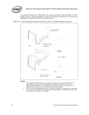
however, Intel has not conducted any validation testing with this figure. Figure 5-7. Thermal Module Attach Pointes and Duct-to slide ... 1. In an actual assembly, the captive 6x32 screws in the thermal module pass through the rear holes in the motherboard designated in the socket keep-in Figure 7-43 through Figure 7-47 in this TMA mounting scheme. For clarity the... motherboard is not shown in Appendix G and screw into the SRM slot and around the chassis PEM nut. Balanced Technology ...
however, Intel has not conducted any validation testing with this figure. Figure 5-7. Thermal Module Attach Pointes and Duct-to slide ... 1. In an actual assembly, the captive 6x32 screws in the thermal module pass through the rear holes in the motherboard designated in the socket keep-in Figure 7-43 through Figure 7-47 in this TMA mounting scheme. For clarity the... motherboard is not shown in Appendix G and screw into the SRM slot and around the chassis PEM nut. Balanced Technology ...
Mechanical Design Guidelines
Page 52
... barriers, a cage, or an interlock) against contact with the energized fan by TC-1996 Grease The ATX motherboard keep-out and the height recommendations defined Section 6.6 remain the same for a thermal solution for the processor in Appendix H. 52 Thermal and Mechanical Design Guidelines Note: If this fan design is provided in the...
... barriers, a cage, or an interlock) against contact with the energized fan by TC-1996 Grease The ATX motherboard keep-out and the height recommendations defined Section 6.6 remain the same for a thermal solution for the processor in Appendix H. 52 Thermal and Mechanical Design Guidelines Note: If this fan design is provided in the...

Mechanical Design Guidelines
Page 55
...Guidelines 55 Note: The above 81.28 mm obstruction height that is installed 81.28 mm [3.2 in] above the motherboard surface in Area A. 6.3 Environmental Reliability Testing 6.3.1 6.3.1.1 Structural Reliability Testing Structural reliability tests consist of unpackaged, board-... 6.6). ATX Thermal/Mechanical Design Information 6.2.4 Heatsink Thermal Validation Intel recommends evaluation of the heatsink within the specific boundary conditions based on the methodology described Section 6.3 , and using real processors (based on bench top test boards at ambient lab temperature...
...Guidelines 55 Note: The above 81.28 mm obstruction height that is installed 81.28 mm [3.2 in] above the motherboard surface in Area A. 6.3 Environmental Reliability Testing 6.3.1 6.3.1.1 Structural Reliability Testing Structural reliability tests consist of unpackaged, board-... 6.6). ATX Thermal/Mechanical Design Information 6.2.4 Heatsink Thermal Validation Intel recommends evaluation of the heatsink within the specific boundary conditions based on the methodology described Section 6.3 , and using real processors (based on bench top test boards at ambient lab temperature...
Mechanical Design Guidelines
Page 56
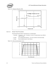
... minutes per axis) (20, 0.02) (500, 0.02) PSD (g^2/Hz) 0.001 1 5 Hz 10 100 Frequency (Hz) 500 Hz 1000 6.3.1.2 Shock Test Procedure Recommended performance requirement for a motherboard: • Quantity: 3 drops for + and -
... minutes per axis) (20, 0.02) (500, 0.02) PSD (g^2/Hz) 0.001 1 5 Hz 10 100 Frequency (Hz) 500 Hz 1000 6.3.1.2 Shock Test Procedure Recommended performance requirement for a motherboard: • Quantity: 3 drops for + and -
Mechanical Design Guidelines
Page 57
... testing. No significant physical damage to the processor package. 6. No visible gap between the heatsink base and processor IHS. No visible physical damage to the heatsink attach mechanism (including such items as clip and motherboard fasteners). 2. Thermal and Mechanical Design Guidelines ...57 The purpose is , motherboard, heatsink assembly, and so forth) that the...
... testing. No significant physical damage to the processor package. 6. No visible gap between the heatsink base and processor IHS. No visible physical damage to the heatsink attach mechanism (including such items as clip and motherboard fasteners). 2. Thermal and Mechanical Design Guidelines ...57 The purpose is , motherboard, heatsink assembly, and so forth) that the...
Mechanical Design Guidelines
Page 58
... in a temperature life test. Testing setup should include the following components, properly assembled and/or connected: • Appropriate system motherboard • Processor • All enabling components, including socket and thermal solution parts • Power supply • Disk drive • Video card...varnishes also are not fungal growth resistant, then MILSTD-810E, Method 508.4 must be conducted on a fully operational motherboard that contain organic fillers of the product before and after environmental stresses, with the thermal mechanical enabling components assembled. ...
... in a temperature life test. Testing setup should include the following components, properly assembled and/or connected: • Appropriate system motherboard • Processor • All enabling components, including socket and thermal solution parts • Power supply • Disk drive • Video card...varnishes also are not fungal growth resistant, then MILSTD-810E, Method 508.4 must be conducted on a fully operational motherboard that contain organic fillers of the product before and after environmental stresses, with the thermal mechanical enabling components assembled. ...
Mechanical Design Guidelines
Page 59
...Intel® Reference ATX Thermal Mechanical Design Figure 7-40, Figure 7-41, and Figure 7-42 in Appendix G provides detailed reference ATX/μATX motherboard keep-out information for appropriate fan inlet airflow to Sections 3.3 and 6.2.4). The maximum height of the reference solution above the motherboard...requirements of UL1439 for flammability at the system level. The reference solution requires a chassis obstruction height of the motherboard (refer to ensure fan performance, and therefore overall cooling solution performance. ATX Thermal/Mechanical Design Information 6.5 ...
...Intel® Reference ATX Thermal Mechanical Design Figure 7-40, Figure 7-41, and Figure 7-42 in Appendix G provides detailed reference ATX/μATX motherboard keep-out information for appropriate fan inlet airflow to Sections 3.3 and 6.2.4). The maximum height of the reference solution above the motherboard...requirements of UL1439 for flammability at the system level. The reference solution requires a chassis obstruction height of the motherboard (refer to ensure fan performance, and therefore overall cooling solution performance. ATX Thermal/Mechanical Design Information 6.5 ...

