
User Guide
Page 3
...; Intelligent I/O Processor 8 2.2.2 Intel® Smart 3 FlashFile™ Flash Memory 9 2.2.3 SDRAM (Cache 9 2.2.4 SATA Controllers 9 2.2.5 Audible Alarm 9 2.2.6 SATA Connectors 10 2.2.7 PCI Interface 10 2.2.8 SRCS14L Jumpers 10 2.2.9 Diagnostic Features 11 2.3 Architecture Features (HW 13 2.4 Electrical Characteristics 13 2.5 Environmental Specifications 13 2.6 Supported Hard Drive Technology 13 3 Software ...14 3.1 Software Architecture Overview 14 3.1.1 User Interface 15 3.1.2 System Management 15 3.1.3 Common Layers 16 3.1.4 RAID Firmware 16 4 RAID Functionality and...
...; Intelligent I/O Processor 8 2.2.2 Intel® Smart 3 FlashFile™ Flash Memory 9 2.2.3 SDRAM (Cache 9 2.2.4 SATA Controllers 9 2.2.5 Audible Alarm 9 2.2.6 SATA Connectors 10 2.2.7 PCI Interface 10 2.2.8 SRCS14L Jumpers 10 2.2.9 Diagnostic Features 11 2.3 Architecture Features (HW 13 2.4 Electrical Characteristics 13 2.5 Environmental Specifications 13 2.6 Supported Hard Drive Technology 13 3 Software ...14 3.1 Software Architecture Overview 14 3.1.1 User Interface 15 3.1.2 System Management 15 3.1.3 Common Layers 16 3.1.4 RAID Firmware 16 4 RAID Functionality and...

User Guide
Page 4
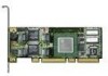
... Auto-declare Hot Fix (Spare) Drive 25 RAID Array Drive Roaming 25 On-line RAID Array Configurations 25 Background Initialization and Instant Availability 27 PCI Hot Plug 27 5 Certifications and Supported Technologies 28 5.1 OS Certifications 28 5.2 Electronic Regulatory Agencies Certifications (Hardware 29 5.3 Supported Specifications and Standards 31 6 Technical Drawings and Diagrams 32 7 Appendices...33 7.1 Referenced Documentation 33 7.2 BIOS Boot Messages 33 Figures 1 SRCS14L RAID Controller Physical Layout 8 2 Jumper Settings and Pin Numbers 10 3 LED Labels...
... Auto-declare Hot Fix (Spare) Drive 25 RAID Array Drive Roaming 25 On-line RAID Array Configurations 25 Background Initialization and Instant Availability 27 PCI Hot Plug 27 5 Certifications and Supported Technologies 28 5.1 OS Certifications 28 5.2 Electronic Regulatory Agencies Certifications (Hardware 29 5.3 Supported Specifications and Standards 31 6 Technical Drawings and Diagrams 32 7 Appendices...33 7.1 Referenced Documentation 33 7.2 BIOS Boot Messages 33 Figures 1 SRCS14L RAID Controller Physical Layout 8 2 Jumper Settings and Pin Numbers 10 3 LED Labels...

User Guide
Page 5
...(Sheet 1 of Independent Disks SCSI Accessed Fault Tolerant Enclosure Serial AT Attachment Single Ended SCSI device. Introduction Intel® Integrated RAID Controller SRCS14L 1 1.1 Acronyms The following acronyms may be used throughout this document. a system management specification Error Correction Code (also error correcting code and error correcting circuits) Flash Recovery Utility Flash Update Utility Firmware Gigabit Gigabyte Host Bus Adapter Intel Integrated RAID Kilobit Kilobyte Low Voltage Differential SCSI Megabit Megabyte Printed Circuit Board Peripheral Component Interconnect...
...(Sheet 1 of Independent Disks SCSI Accessed Fault Tolerant Enclosure Serial AT Attachment Single Ended SCSI device. Introduction Intel® Integrated RAID Controller SRCS14L 1 1.1 Acronyms The following acronyms may be used throughout this document. a system management specification Error Correction Code (also error correcting code and error correcting circuits) Flash Recovery Utility Flash Update Utility Firmware Gigabit Gigabyte Host Bus Adapter Intel Integrated RAID Kilobit Kilobyte Low Voltage Differential SCSI Megabit Megabyte Printed Circuit Board Peripheral Component Interconnect...
User Guide
Page 6
... capacity expansion without reboot • RAID array roaming 6 Technical Product Specification Storage Console Plus: A GUI-based, menu-driven tool used for setting up to four hard drives connected to the four SATA ports on IIR Controllers. BIOS utility accessed at system POST. 1.2 Documentation Conventions The terms "RAID controller" and "the controller" are supported with limited compatibility validation: • Windows 2000 Server • Red Hat Linux 7.2 • TurboLinux* 7.0 Server List of the RAID PCI add-in card. 1.3 Product Overview The SRCS14L is a PCI-based, low...
... capacity expansion without reboot • RAID array roaming 6 Technical Product Specification Storage Console Plus: A GUI-based, menu-driven tool used for setting up to four hard drives connected to the four SATA ports on IIR Controllers. BIOS utility accessed at system POST. 1.2 Documentation Conventions The terms "RAID controller" and "the controller" are supported with limited compatibility validation: • Windows 2000 Server • Red Hat Linux 7.2 • TurboLinux* 7.0 Server List of the RAID PCI add-in card. 1.3 Product Overview The SRCS14L is a PCI-based, low...

User Guide
Page 7
Intel® Integrated RAID Controller SRCS14L • Instant availability and background initialization • Automatic rebuild with private (dedicated) or pooled (global) hot fix (spare) drives • Variable data strip size configurable per array • 64MB of ECC SDRAM support • Read/write controller caching • Hot plug disk drive auto detection configurable for non-intelligent enclosures • PCI Hot plug support Technical Product Specification 7
Intel® Integrated RAID Controller SRCS14L • Instant availability and background initialization • Automatic rebuild with private (dedicated) or pooled (global) hot fix (spare) drives • Variable data strip size configurable per array • 64MB of ECC SDRAM support • Read/write controller caching • Hot plug disk drive auto detection configurable for non-intelligent enclosures • PCI Hot plug support Technical Product Specification 7
User Guide
Page 9
... RAID firmware. The IOP memory controller provides single-bit ECC error correction. Audible Alarm An 80db audible alarm is online. See Figure 2: Jumper Settings and Pin Numbers for firmware updates and recovery. The core processor runs at 100 MHz. PCI-to-PCI Bridge The PCI-to 1.5 Gbps. For firmware recovery, set the IOP mode select jumper J1 to the 80960 core processor, including SDRAM and Flash. SDRAM (Cache) The SRCS14L provides 64MB of most instructions. Intel® Smart 3 FlashFile™ Flash...
... RAID firmware. The IOP memory controller provides single-bit ECC error correction. Audible Alarm An 80db audible alarm is online. See Figure 2: Jumper Settings and Pin Numbers for firmware updates and recovery. The core processor runs at 100 MHz. PCI-to-PCI Bridge The PCI-to 1.5 Gbps. For firmware recovery, set the IOP mode select jumper J1 to the 80960 core processor, including SDRAM and Flash. SDRAM (Cache) The SRCS14L provides 64MB of most instructions. Intel® Smart 3 FlashFile™ Flash...

User Guide
Page 11
...PCI bus is used to place the IOP in reset mode with firmware recovery enabled. J1 - IOP mode select jumper block: This jumper is forced to be erased and reprogrammed. During normal operation and during normal firmware updates, the jumper is in reset, which enables the flash chip to 33 MHz. Intel® Integrated RAID Controller SRCS14L Table 2. Controller Jumper Settings Jumper Block Jumper Position Jumper on pins [1-2] J1 Jumper on pins [2-3] No jumpers Jumper on pins [1-2] J4 Jumper on pins [2-3] No jumpers Definition IOP is installed on pins 2-3 (or removed...
...PCI bus is used to place the IOP in reset mode with firmware recovery enabled. J1 - IOP mode select jumper block: This jumper is forced to be erased and reprogrammed. During normal operation and during normal firmware updates, the jumper is in reset, which enables the flash chip to 33 MHz. Intel® Integrated RAID Controller SRCS14L Table 2. Controller Jumper Settings Jumper Block Jumper Position Jumper on pins [1-2] J1 Jumper on pins [2-3] No jumpers Jumper on pins [1-2] J4 Jumper on pins [2-3] No jumpers Definition IOP is installed on pins 2-3 (or removed...
User Guide
Page 12
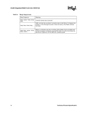
Intel® Integrated RAID Controller SRCS14L Table 4. pause - .... RAID controller has a problem. beep, beep - Memory or firmware may be available from the boot message. Beep Sequences Beep Sequence Meaning beep - A possible cause is disk failure. To diagnose the problem, run the Storage Console to recover the firmware as described in Appendix A of the RAID controller beep, beep, beep, beep, .... and array. If necessary, use the FRU utility to check the status of the SRCS14L hardware guide. 12 Technical...
Intel® Integrated RAID Controller SRCS14L Table 4. pause - .... RAID controller has a problem. beep, beep - Memory or firmware may be available from the boot message. Beep Sequences Beep Sequence Meaning beep - A possible cause is disk failure. To diagnose the problem, run the Storage Console to recover the firmware as described in Appendix A of the RAID controller beep, beep, beep, beep, .... and array. If necessary, use the FRU utility to check the status of the SRCS14L hardware guide. 12 Technical...
User Guide
Page 14
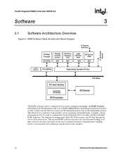
..., I/O processor, and I /O Device The RAID software stack is used to incorporate new technology and provide for a consistent 'look and feel' across operating system platforms. A simple, custom messaging protocol is composed of two major component groupings: the RAID firmware embedded in the Flash memory and a set of host resident drivers and utilities installed on the reuse of abstraction layers. Intel® Integrated RAID Controller SRCS14L Software 3 To Operating System 3.1 Software Architecture Overview...
..., I/O processor, and I /O Device The RAID software stack is used to incorporate new technology and provide for a consistent 'look and feel' across operating system platforms. A simple, custom messaging protocol is composed of two major component groupings: the RAID firmware embedded in the Flash memory and a set of host resident drivers and utilities installed on the reuse of abstraction layers. Intel® Integrated RAID Controller SRCS14L Software 3 To Operating System 3.1 Software Architecture Overview...
User Guide
Page 15
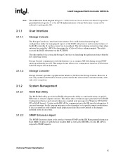
... is during system POST and from within the host OS. The other method of the RAID controller. Intel® Integrated RAID Controller SRCS14L Note: The architecture block diagram in MAPI format). Certain blocks may or may not be accessed via two methods. Storage Console+ Storage Console+ provides a graphical user interface (GUI) for Windows NT/9x/200/ XP, in Figure 4: RAID Software Stack Architecture Block Diagram is via a common API both OS and pre...
... is during system POST and from within the host OS. The other method of the RAID controller. Intel® Integrated RAID Controller SRCS14L Note: The architecture block diagram in MAPI format). Certain blocks may or may not be accessed via two methods. Storage Console+ Storage Console+ provides a graphical user interface (GUI) for Windows NT/9x/200/ XP, in Figure 4: RAID Software Stack Architecture Block Diagram is via a common API both OS and pre...

User Guide
Page 16
... IIR API is a C++ class library consisting of service and library modules. Intel® Integrated RAID Controller SRCS14L 3.1.3 3.1.3.1 3.1.3.2 3.1.3.3 3.1.3.4 3.1.4 Common Layers PCI BIOS The PCI BIOS is the Expansion ROM software as a daemon on Unix-based systems. In order to use the remote access capability, an administrator has to create user accounts. Operating System Driver The IIR device driver is the OS specific driver that communicates between the host resident application and the IIR HBA...
... IIR API is a C++ class library consisting of service and library modules. Intel® Integrated RAID Controller SRCS14L 3.1.3 3.1.3.1 3.1.3.2 3.1.3.3 3.1.3.4 3.1.4 Common Layers PCI BIOS The PCI BIOS is the Expansion ROM software as a daemon on Unix-based systems. In order to use the remote access capability, an administrator has to create user accounts. Operating System Driver The IIR device driver is the OS specific driver that communicates between the host resident application and the IIR HBA...

User Guide
Page 17
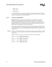
A logical drive is created 4. However, before they can create a logical drive manually by a process called initialization. Array drives always consist of logical drives and consist of a physical device. So, in order to create a data drive (host drive/RAID volume) and present it to the host operating system, the RAID firmware typically follows these hard drives must be used as components. The logical drives are located on the lowest level of the hierarchy. This includes hard disk drives, removable hard disks, and some level of redundancy) data storage medium...
A logical drive is created 4. However, before they can create a logical drive manually by a process called initialization. Array drives always consist of logical drives and consist of a physical device. So, in order to create a data drive (host drive/RAID volume) and present it to the host operating system, the RAID firmware typically follows these hard drives must be used as components. The logical drives are located on the lowest level of the hierarchy. This includes hard disk drives, removable hard disks, and some level of redundancy) data storage medium...
User Guide
Page 18
... the hierarchy by using the Merge feature. It can manually create an array drive by the RAID firmware. Warning: Any data located on this feature if the new host drive already contains data that are transparent to destroy. Within the Storage Console utility, each of the logical drives into one single host drive. Intel® Integrated RAID Controller SRCS14L • RAID 4 drives • RAID 5 drives • RAID 10 drives You can then be configured as a new host drive on the new host drive (created from the capacity expansion) will be combined...
... the hierarchy by using the Merge feature. It can manually create an array drive by the RAID firmware. Warning: Any data located on this feature if the new host drive already contains data that are transparent to destroy. Within the Storage Console utility, each of the logical drives into one single host drive. Intel® Integrated RAID Controller SRCS14L • RAID 4 drives • RAID 5 drives • RAID 10 drives You can then be configured as a new host drive on the new host drive (created from the capacity expansion) will be combined...

User Guide
Page 19
... RW Build RW Ready RW Rebuild RW Expand RW Fail RW Error RO Patch RW RW = Read Write RO = Read Only Drive Type RAID 4 / 5 / 10 RAID 1 / 4 / 5 / 10 RAID 1 / 4 / 5 / 10 RAID 1 / 4 / 5 / 10 RAID 4 / 5 RAID 1 / 4 / 5 / 10 RAID 4 / 5 / 10 RAID 4 / 5 Redundant Description No No Yes No Yes when adding new drives. The array drive is set to the drive Technical Product Specification 19 This status indicates that one logical drive has failed. Intel® Integrated RAID Controller SRCS14L 4.1.5 RAID Host/Array Drive Statuses Table 8 lists the available states of drive. Table...
... RW Build RW Ready RW Rebuild RW Expand RW Fail RW Error RO Patch RW RW = Read Write RO = Read Only Drive Type RAID 4 / 5 / 10 RAID 1 / 4 / 5 / 10 RAID 1 / 4 / 5 / 10 RAID 1 / 4 / 5 / 10 RAID 4 / 5 RAID 1 / 4 / 5 / 10 RAID 4 / 5 / 10 RAID 4 / 5 Redundant Description No No Yes No Yes when adding new drives. The array drive is set to the drive Technical Product Specification 19 This status indicates that one logical drive has failed. Intel® Integrated RAID Controller SRCS14L 4.1.5 RAID Host/Array Drive Statuses Table 8 lists the available states of drive. Table...

User Guide
Page 20
Logical Drive Statuses Drive Status Ready Missing Fault RW = Read Write RO = Read Only Attribute RW RW Description The drive is the physical drive limit divided by the number of four host drives. The drive attribute indicates the level of host OS access to the drive. 4.1.7 RAID Controller Drive Limitations (Host, Array, Logical, and Physical) The following : • Four SATA ports • Cabling that the SRCS14L controller has a maximum limitation of ports (four) on ) a single array drive. Also, each array drive must be associated with (or reside...
Logical Drive Statuses Drive Status Ready Missing Fault RW = Read Write RO = Read Only Attribute RW RW Description The drive is the physical drive limit divided by the number of four host drives. The drive attribute indicates the level of host OS access to the drive. 4.1.7 RAID Controller Drive Limitations (Host, Array, Logical, and Physical) The following : • Four SATA ports • Cabling that the SRCS14L controller has a maximum limitation of ports (four) on ) a single array drive. Also, each array drive must be associated with (or reside...
User Guide
Page 21
... RAID View Hard Disk Information controller with exception to be run locally or remotely using StorCon text-based) View Statistics View Events Allows the viewing of I/O activity of host, logical, and physical drives and cache activity Allows the viewing and saving of all supported operating systems. Storage Console+ (StorCon+) GUI based version of the RAID controller in ASCII file for troubleshooting or documentation. From the menu, choose Advanced Setup -> Configure Controller -> Controller Settings. A destructive surface-check...
... RAID View Hard Disk Information controller with exception to be run locally or remotely using StorCon text-based) View Statistics View Events Allows the viewing of I/O activity of host, logical, and physical drives and cache activity Allows the viewing and saving of all supported operating systems. Storage Console+ (StorCon+) GUI based version of the RAID controller in ASCII file for troubleshooting or documentation. From the menu, choose Advanced Setup -> Configure Controller -> Controller Settings. A destructive surface-check...
User Guide
Page 22
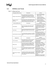
...host drive. Actions • Is accessed via DOS utility • Is accessed via the Storage Console during boot up (+) or from corrupted firmware. The SRCS14L does not support the addition of the other: • Controller caching • Disk drive caching 22 Technical Product Specification Utilities And Tools Firmware Firmware Update Firmware Recovery Description Utility that the controller's J4 jumper be added in the Reset/ Firmware Recovery mode and the use of caching related to recover from within the host OS menu Advanced Setup -> Configure Controller -> Firmware Update...
...host drive. Actions • Is accessed via DOS utility • Is accessed via the Storage Console during boot up (+) or from corrupted firmware. The SRCS14L does not support the addition of the other: • Controller caching • Disk drive caching 22 Technical Product Specification Utilities And Tools Firmware Firmware Update Firmware Recovery Description Utility that the controller's J4 jumper be added in the Reset/ Firmware Recovery mode and the use of caching related to recover from within the host OS menu Advanced Setup -> Configure Controller -> Firmware Update...

User Guide
Page 23
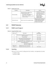
... use the controller's memory. Intel® Integrated RAID Controller SRCS14L Caching can be enabled on the controller, which sets caching on all the RAID array/host drives configured on the controller (SDRAM that is either embedded or an inserted DIMM module). In this method, the cache memory that support optional battery backup. The other caching mode is not protected by the battery backup unit of the hard disk drives. The battery backup only protects data that is located in the controller cache. 4.3.2.1 Controller Cache...
... use the controller's memory. Intel® Integrated RAID Controller SRCS14L Caching can be enabled on the controller, which sets caching on all the RAID array/host drives configured on the controller (SDRAM that is either embedded or an inserted DIMM module). In this method, the cache memory that support optional battery backup. The other caching mode is not protected by the battery backup unit of the hard disk drives. The battery backup only protects data that is located in the controller cache. 4.3.2.1 Controller Cache...
User Guide
Page 24
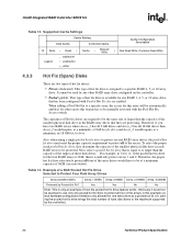
... is assigned to be automatically enabled, for any other arrays this array will be protected. adding the pooled hot fix drive brings the total number of hard disk drives to be of a minimum capacity of hot fix drive is only an example of the array drives would require, at a minimum, an 18 GB hot fix drive. Intel® Integrated RAID Controller SRCS14L Table 13. Therefore, the proper hot fix drive selection to protect all...
... is assigned to be automatically enabled, for any other arrays this array will be protected. adding the pooled hot fix drive brings the total number of hard disk drives to be of a minimum capacity of hot fix drive is only an example of the array drives would require, at a minimum, an 18 GB hot fix drive. Intel® Integrated RAID Controller SRCS14L Table 13. Therefore, the proper hot fix drive selection to protect all...
User Guide
Page 25
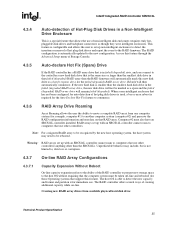
..., data loss or corruption. 4.3.7 On-line RAID Array Configurations 4.3.7.1 Capacity Expansion Without Reboot On-line capacity expansion refers to the ability of the RAID controller to present new storage space to the controller a new hard disk drive that is the same size or larger than the smallest disk drive in that support this new disk drive as a hot fix (spare) drive for those Operating systems that failed (degraded) RAID array then the RAID firmware will automatically mark this feature). If the new hard disk is smaller than the SRCS14L). Unpredictable...
..., data loss or corruption. 4.3.7 On-line RAID Array Configurations 4.3.7.1 Capacity Expansion Without Reboot On-line capacity expansion refers to the ability of the RAID controller to present new storage space to the controller a new hard disk drive that is the same size or larger than the smallest disk drive in that support this new disk drive as a hot fix (spare) drive for those Operating systems that failed (degraded) RAID array then the RAID firmware will automatically mark this feature). If the new hard disk is smaller than the SRCS14L). Unpredictable...


