
Operation Manual
Page 1
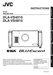
... use the unit correctly. which are located on the back of this unit by operating this equipment other than instructed in order to operate the unit, in this JVC product. Serial No. D-ILA PROJECTOR DLA-VS4010 DLA-VS4810 INSTRUCTIONS Connection and Installation Network Settings Operation and Settings Others . Please study this information for any problems resulting from misuse of the cabinet. Retain this instruction manual carefully before starting to use : Enter below the model No. Getting Started...
... use the unit correctly. which are located on the back of this unit by operating this equipment other than instructed in order to operate the unit, in this JVC product. Serial No. D-ILA PROJECTOR DLA-VS4010 DLA-VS4810 INSTRUCTIONS Connection and Installation Network Settings Operation and Settings Others . Please study this information for any problems resulting from misuse of the cabinet. Retain this instruction manual carefully before starting to use : Enter below the model No. Getting Started...
Operation Manual
Page 2
... the manufacturer's instructions, and should be easily unplugged. - If the installation place is operated in a residential area is operated. - But IMPROPER USE CAN RESULT IN POTENTIAL ELECTRICAL SHOCK OR FIRE HAZARD. Unplug this product near a wall outlet where the plug can perform many useful functions. Do not use . - Do not use and service. GSGV, January 18, 1991: The sound pressure level...
... the manufacturer's instructions, and should be easily unplugged. - If the installation place is operated in a residential area is operated. - But IMPROPER USE CAN RESULT IN POTENTIAL ELECTRICAL SHOCK OR FIRE HAZARD. Unplug this product near a wall outlet where the plug can perform many useful functions. Do not use . - Do not use and service. GSGV, January 18, 1991: The sound pressure level...
Operation Manual
Page 3
... way. Adjust only those controls that could lead to lightning and power line surges. - If the light-source lamp is damaged. b) If liquid has been spilled, or objects have fallen on or pinched by the manufacturer or with a three-wire plug. The light-source lamp used replacement parts specified by items placed upon or against electric shock. - Getting Started - This plug will...
... way. Adjust only those controls that could lead to lightning and power line surges. - If the light-source lamp is damaged. b) If liquid has been spilled, or objects have fallen on or pinched by the manufacturer or with a three-wire plug. The light-source lamp used replacement parts specified by items placed upon or against electric shock. - Getting Started - This plug will...

Operation Manual
Page 4
... compatibility we recommend to the terminal which is colored blue must be connected to use the cables not exceeding the following power cord. Power cord The power supply voltage rating of this equipment may not correspond with the letter L or colored red. . 4 EMC Supplement - Power cord For European continent countries WARNING: Do not cut off the main plug from railways, transmitters, overhead power lines, etc). If a new main plug...
... compatibility we recommend to the terminal which is colored blue must be connected to use the cables not exceeding the following power cord. Power cord The power supply voltage rating of this equipment may not correspond with the letter L or colored red. . 4 EMC Supplement - Power cord For European continent countries WARNING: Do not cut off the main plug from railways, transmitters, overhead power lines, etc). If a new main plug...
Operation Manual
Page 8
... 10 Connection and Installation Installation 11 Optional Projection Lens 11 Minimum Space Required 11 Projector Installation Angle 12 Installing the Projector and Screen 13 Screen Size and Projection Distance 16 Connecting Video Signals of the Computer 18 Connection During Single-Screen Mode Display 18 Connection During Two-Screen/Four-Screen Mode Display 20 Network Settings Connection Using a LAN Cable 22 Connection Example 22 Specifications of PC for Controlling this Projector 23 Turning On the Main Power 24 IP Address Settings 25...
... 10 Connection and Installation Installation 11 Optional Projection Lens 11 Minimum Space Required 11 Projector Installation Angle 12 Installing the Projector and Screen 13 Screen Size and Projection Distance 16 Connecting Video Signals of the Computer 18 Connection During Single-Screen Mode Display 18 Connection During Two-Screen/Four-Screen Mode Display 20 Network Settings Connection Using a LAN Cable 22 Connection Example 22 Specifications of PC for Controlling this Projector 23 Turning On the Main Power 24 IP Address Settings 25...

Operation Manual
Page 10
... (Red) : When in the standby mode (main power supply is the input terminal for video signals. Lit (Green) : When power is connected to the network. H [e-shift Sync] Terminal (DLA-VS4810 only) This is ON) turns on the LD block lifespan appears when the lifetime of the projector unit. This projector can be controlled by the symbol X. T Main Power Supply Switch Use this to turn ON/OFF the main power supply of...
... (Red) : When in the standby mode (main power supply is the input terminal for video signals. Lit (Green) : When power is connected to the network. H [e-shift Sync] Terminal (DLA-VS4810 only) This is ON) turns on the LD block lifespan appears when the lifetime of the projector unit. This projector can be controlled by the symbol X. T Main Power Supply Switch Use this to turn ON/OFF the main power supply of...

Operation Manual
Page 13
...2 USB LAN RS-232C DVI 3 OPERATE I/B STANDBY/ON LAMP DVI 4 WARNING When shift amount in use, you can make use , you can shift the projection screen position vertically between 0% to ±15%, and horizontally between 0% to the screen. Screen When shift amount in the left direction is -25 % Install the ...1/4 position from the left /right direction is 0 % Install the projector such that the lower end of the projection screen is at the same height as the center of the lens. Connection and Installation Installing the Projector and Screen It is recommended that the upper end...
...2 USB LAN RS-232C DVI 3 OPERATE I/B STANDBY/ON LAMP DVI 4 WARNING When shift amount in use, you can make use , you can shift the projection screen position vertically between 0% to ±15%, and horizontally between 0% to the screen. Screen When shift amount in the left direction is -25 % Install the ...1/4 position from the left /right direction is 0 % Install the projector such that the lower end of the projection screen is at the same height as the center of the lens. Connection and Installation Installing the Projector and Screen It is recommended that the upper end...
Operation Manual
Page 18
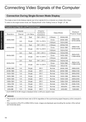
...the synchronizing signal frequency at the computer's end. 0 If the resolution of the PC is 2048×1200 or lower, images are displayed upon doubling the number of the Computer Connection During Single-Screen Mode Display The single-screen mode displays signals (up ...215;480 * (DLA-VS4810) An 8K image is displayed when e-shift sync signal is input. To select to the single-screen mode, set "Display Mode" in the "Setting" menu to "Single". (P. 38) Possible Input Signals and Projected Image Resolution Computer Channel Link Status Projector Terminal for Connection Output Status 2ch Dual...
...the synchronizing signal frequency at the computer's end. 0 If the resolution of the PC is 2048×1200 or lower, images are displayed upon doubling the number of the Computer Connection During Single-Screen Mode Display The single-screen mode displays signals (up ...215;480 * (DLA-VS4810) An 8K image is displayed when e-shift sync signal is input. To select to the single-screen mode, set "Display Mode" in the "Setting" menu to "Single". (P. 38) Possible Input Signals and Projected Image Resolution Computer Channel Link Status Projector Terminal for Connection Output Status 2ch Dual...

Operation Manual
Page 20
... 1 DVI 3 2400 DVI 1 DVI 3 DVI 2 DVI 4 1200 2048 . 2048 . 20 To select the four-screen mode, set "Display Mode" in the two-screen mode, the screen appears blue (or black depending on the setting) when there is no input. To select the two-screen mode, set "Display Mode" to "Cross". (P. 38) Possible Input Signals and Projected Image Resolution 2048×1200 2048×1080 1920×1200 1920×...
... 1 DVI 3 2400 DVI 1 DVI 3 DVI 2 DVI 4 1200 2048 . 2048 . 20 To select the four-screen mode, set "Display Mode" in the two-screen mode, the screen appears blue (or black depending on the setting) when there is no input. To select the two-screen mode, set "Display Mode" to "Cross". (P. 38) Possible Input Signals and Projected Image Resolution 2048×1200 2048×1080 1920×1200 1920×...

Operation Manual
Page 22
... simply by configuring the network. Network Settings Connection Using a LAN Cable Connect this projector, the computer for controlling this projector, and the switching hub using other network, be sure to consult the network administrator of the network in use or refer to technical books on networks. Switching Hub To Network Terminal DVI 1 e-shift Sync DVI 2 USB LAN RS-232C To LAN Terminal 2 RS-232C DVI 3 OPERATE I /B STANDBY/ON LAMP...
... simply by configuring the network. Network Settings Connection Using a LAN Cable Connect this projector, the computer for controlling this projector, and the switching hub using other network, be sure to consult the network administrator of the network in use or refer to technical books on networks. Switching Hub To Network Terminal DVI 1 e-shift Sync DVI 2 USB LAN RS-232C To LAN Terminal 2 RS-232C DVI 3 OPERATE I /B STANDBY/ON LAMP...

Operation Manual
Page 28
... projector and the controlling computer using a USB cable. 0 You need to install a driver in a LAN where a DHCP server does not exist, the projector will start up using a USB cable. When assigning an IP address from the DHCP server, access this projector from the DHCP Server The IP address is automatically assigned by the DHCP server. 1 After connecting, turn on the main power 0 Refer to...
... projector and the controlling computer using a USB cable. 0 You need to install a driver in a LAN where a DHCP server does not exist, the projector will start up using a USB cable. When assigning an IP address from the DHCP server, access this projector from the DHCP Server The IP address is automatically assigned by the DHCP server. 1 After connecting, turn on the main power 0 Refer to...

Operation Manual
Page 31
... "Main" menu to end the projection 0 The projector switches to the standby mode, and the [STANDBY/ON] indicator lights up in the cool down the main power supply or unplug the power cord when in red. 0 You can also turn off the power by pressing the [OPERATE Z] button on the inner buttons (a / b). (Fine control) The outer buttons (d / c) change the focus when they are depressed. (Coarse control) 6 Select a screen mode for...
... "Main" menu to end the projection 0 The projector switches to the standby mode, and the [STANDBY/ON] indicator lights up in the cool down the main power supply or unplug the power cord when in red. 0 You can also turn off the power by pressing the [OPERATE Z] button on the inner buttons (a / b). (Fine control) The outer buttons (d / c) change the focus when they are depressed. (Coarse control) 6 Select a screen mode for...

Operation Manual
Page 34
...Menu Name (1) Main (2) Image (3) Setting (4) Convergence (5) Lens (6) Option Page Display Item Power Warning Status Light Source Time Signal Status Temperature Hide Brightness Contrast Gamma Hide Input Level Display Mode Red Blue Test Pattern Zoom Focus Shift Test Pattern Flip Light Source Power Back Color Message Display Test Pattern Simplified Description of Item Power ON/OFF operation Error code display LD block information display Input signal information display Projector's interior temperature display Mute operation Brightness adjustment Contrast adjustment Gamma setting Mute operation...
...Menu Name (1) Main (2) Image (3) Setting (4) Convergence (5) Lens (6) Option Page Display Item Power Warning Status Light Source Time Signal Status Temperature Hide Brightness Contrast Gamma Hide Input Level Display Mode Red Blue Test Pattern Zoom Focus Shift Test Pattern Flip Light Source Power Back Color Message Display Test Pattern Simplified Description of Item Power ON/OFF operation Error code display LD block information display Input signal information display Projector's interior temperature display Mute operation Brightness adjustment Contrast adjustment Gamma setting Mute operation...

Operation Manual
Page 35
... time switches the mode in the sequence of the projector cannot be selectable. MEMO 0 The following operating modes of the projector are displayed to the projector. Item Power Setting Value ON OFF Description Turns on the LD block. host PJ-1 user: root Logout Main Image Setting Convergence Lens Option License Power ON OFF PROJECTION Light Source Time 10h59m Signal Status DVI Rate(Hz) Pixel H Pixel V Link...
... time switches the mode in the sequence of the projector cannot be selectable. MEMO 0 The following operating modes of the projector are displayed to the projector. Item Power Setting Value ON OFF Description Turns on the LD block. host PJ-1 user: root Logout Main Image Setting Convergence Lens Option License Power ON OFF PROJECTION Light Source Time 10h59m Signal Status DVI Rate(Hz) Pixel H Pixel V Link...

Operation Manual
Page 39
... cross hatch pattern. (4) Convergence Menu This menu is flipped horizontally or vertically, the horizontal and vertical directions are used for adjustment in units of 1/4 pixels, and the inner buttons in the optical system. Cross Hatch : Displays the cross hatch pattern. Main Image Setting Convergence Lens Option License Red U Blue L RL D Test Pattern OFF OFF host PJ-1 user: root Logout U R D SET . R OFF Color Bars...
... cross hatch pattern. (4) Convergence Menu This menu is flipped horizontally or vertically, the horizontal and vertical directions are used for adjustment in units of 1/4 pixels, and the inner buttons in the optical system. Cross Hatch : Displays the cross hatch pattern. Main Image Setting Convergence Lens Option License Red U Blue L RL D Test Pattern OFF OFF host PJ-1 user: root Logout U R D SET . R OFF Color Bars...

Operation Manual
Page 41
...-1 user: root Logout Vert. Setting Value ON R OFF ON R OFF Light Source Power R Mode1 Mode2 Back Color R Blue Black Message Display ON R OFF Test Pattern - CAUTION 0 When "OFF" is set, the "No Input", "Out of the LD block to display the message. (6) Option Menu This menu is used for screen display method, LD block brightness and others. ON : Flips image horizontally. For switching the brightness of Range...
...-1 user: root Logout Vert. Setting Value ON R OFF ON R OFF Light Source Power R Mode1 Mode2 Back Color R Blue Black Message Display ON R OFF Test Pattern - CAUTION 0 When "OFF" is set, the "No Input", "Out of the LD block to display the message. (6) Option Menu This menu is used for screen display method, LD block brightness and others. ON : Flips image horizontally. For switching the brightness of Range...

Operation Manual
Page 42
... Name Setting IP Address Setting User Login Password Change Admin. Operate the menus using the computer's browser to 41). Login Password Change E-Mail Setting Test Mail Color Depth Frame Lock Mecha. Administrator Settings Menu Structure For details on page menu (1) to (6), refer to "User Settings Menu" (P. 34 to make adjustments and configure settings. Shutter High Altitude Light Source Time Reset Force Signal Display Mode Signal Status EDID Simplified Description of Item Power ON/OFF operation Error code display LD block information display Input signal information display Projector...
... Name Setting IP Address Setting User Login Password Change Admin. Operate the menus using the computer's browser to 41). Login Password Change E-Mail Setting Test Mail Color Depth Frame Lock Mecha. Administrator Settings Menu Structure For details on page menu (1) to (6), refer to "User Settings Menu" (P. 34 to make adjustments and configure settings. Shutter High Altitude Light Source Time Reset Force Signal Display Mode Signal Status EDID Simplified Description of Item Power ON/OFF operation Error code display LD block information display Input signal information display Projector...
Operation Manual
Page 47
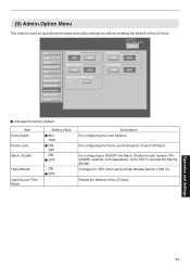
... Depth Frame Lock Mech. Operation and Settings 47 R indicates the factory default. Shutter Setting Value R 8bit 12bit R ON OFF ON R OFF High Altitude Light Source Time Reset ON R OFF - Click "ON" to "ON" when using at high altitude (above 1,500 m). (9) Admin.Option Menu This menu is used for specifying the image and option settings as well as resetting the lifetime of each DVI input. For configuring...
... Depth Frame Lock Mech. Operation and Settings 47 R indicates the factory default. Shutter Setting Value R 8bit 12bit R ON OFF ON R OFF High Altitude Light Source Time Reset ON R OFF - Click "ON" to "ON" when using at high altitude (above 1,500 m). (9) Admin.Option Menu This menu is used for specifying the image and option settings as well as resetting the lifetime of each DVI input. For configuring...

Operation Manual
Page 48
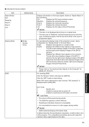
..., : Displays a cross screen using single link. host PJ-1 user: advanced Logout Main Image Setting Convergence Lens Option Admin.Network Admin.E-Mail Admin.Option Admin.Signal License Force Signal OFF SET OFF Signal Status DVI Rate(Hz) Pixel H Pixel V Link 1 60.00 2048 2400 Dual 2 3 60.00 2048 2400 Dual 4 Display Mode 1 13 12 34 EDID Browse... SET Operation and Settings . R indicates the factory default. (10) Admin.Signal Menu This menu is no display...
..., : Displays a cross screen using single link. host PJ-1 user: advanced Logout Main Image Setting Convergence Lens Option Admin.Network Admin.E-Mail Admin.Option Admin.Signal License Force Signal OFF SET OFF Signal Status DVI Rate(Hz) Pixel H Pixel V Link 1 60.00 2048 2400 Dual 2 3 60.00 2048 2400 Dual 4 Display Mode 1 13 12 34 EDID Browse... SET Operation and Settings . R indicates the factory default. (10) Admin.Signal Menu This menu is no display...
Operation Manual
Page 49
... (vertical frequency) turns red in the User Menu. The compatible transmitting device will be displayed for details. (P. 18 to move on the input signals. DVI : Displays the DVI input terminal number. Pixel V : Displays the vertical resolution. Single : Displays input signals on two screens. Double : Displays two different input signals on a single screen. MEMO 0 Please refer to "Connecting Video Signals of the projector. R indicates the factory default. Write "OK" will output the optimum video signal based on four screens. Operation and Settings Error Code...
... (vertical frequency) turns red in the User Menu. The compatible transmitting device will be displayed for details. (P. 18 to move on the input signals. DVI : Displays the DVI input terminal number. Pixel V : Displays the vertical resolution. Single : Displays input signals on two screens. Double : Displays two different input signals on a single screen. MEMO 0 Please refer to "Connecting Video Signals of the projector. R indicates the factory default. Write "OK" will output the optimum video signal based on four screens. Operation and Settings Error Code...