Instruction Manual
Page 3
.... • Do not use this product near water. • Do not use a mount recommended by following conditions: a) When the power supply cord or plug is provided and the manufacturer's instructions have fallen on an unstable cart, stand, or table. Adjust only those controls that could result in ... high temperature, as this product through openings as they may touch dangerous voltage points or short out parts that are provided for service. • Never push objects of any way. ENGLISH Unplug this product yourself, as opening or removing covers may result in a fire...
.... • Do not use this product near water. • Do not use a mount recommended by following conditions: a) When the power supply cord or plug is provided and the manufacturer's instructions have fallen on an unstable cart, stand, or table. Adjust only those controls that could result in ... high temperature, as this product through openings as they may touch dangerous voltage points or short out parts that are provided for service. • Never push objects of any way. ENGLISH Unplug this product yourself, as opening or removing covers may result in a fire...
Instruction Manual
Page 6
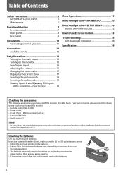
... your monitor, please replace them . Inserting the batteries Use two AA/R6 dry cell batteries. Table of Contents Safety Precautions 2 IMPORTANT SAFEGUARDS 2 Maintenance 5 Parts Identification 7 Remote control 7 Front panel 8 Rear panel 8 Installation 10 Connecting external speakers 11 Connections 12 Available signals 12 Menu Operations 19 Menu Configuration-MAIN MENU 20 Menu Configuration-SET-UP MENU 26 Setting the Power-on Lock 32 How to Use External Control 33 Troubleshooting...
... your monitor, please replace them . Inserting the batteries Use two AA/R6 dry cell batteries. Table of Contents Safety Precautions 2 IMPORTANT SAFEGUARDS 2 Maintenance 5 Parts Identification 7 Remote control 7 Front panel 8 Rear panel 8 Installation 10 Connecting external speakers 11 Connections 12 Available signals 12 Menu Operations 19 Menu Configuration-MAIN MENU 20 Menu Configuration-SET-UP MENU 26 Setting the Power-on Lock 32 How to Use External Control 33 Troubleshooting...
Instruction Manual
Page 7
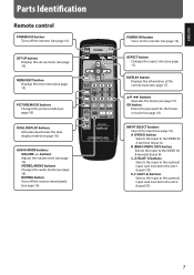
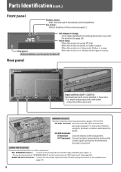
...). AUDIO MODE buttons VOLUME +/- buttons Adjusts the volume level (see page 19). A (VIDEO) button Selects the input to the VIDEO IN B terminal (Input B). B (RGB/COMPO./DVI) button Selects the input to the VIDEO IN A terminal (Input A). MUTING button Turns off the volume immediately (see page 16). POWER ON button Turns on the monitor (see page 16). ASPECT button Changes the aspect ratio (see page 32). OK button Enters the password for the Poweron Lock (see page 17). SET-UP button Displays the set-up menu...
...). AUDIO MODE buttons VOLUME +/- buttons Adjusts the volume level (see page 19). A (VIDEO) button Selects the input to the VIDEO IN B terminal (Input B). B (RGB/COMPO./DVI) button Selects the input to the VIDEO IN A terminal (Input A). MUTING button Turns off the volume immediately (see page 16). POWER ON button Turns on the monitor (see page 16). ASPECT button Changes the aspect ratio (see page 32). OK button Enters the password for the Poweron Lock (see page 17). SET-UP button Displays the set-up menu...
Instruction Manual
Page 8
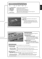
... input cards can be installed in orange. For the control method using this terminal, set "SPEAKER SELECT" on : Lights in orange. When the monitor is in standby mode: Lights in green. Eco sensor: Detects brightness of the remote control toward here. EXT. Parts Identification (cont.) Front panel Remote sensor: Point the front end of the room (see page 25). OUT terminal: Connect another component to the instructions of...
... input cards can be installed in orange. For the control method using this terminal, set "SPEAKER SELECT" on : Lights in orange. When the monitor is in standby mode: Lights in green. Eco sensor: Detects brightness of the remote control toward here. EXT. Parts Identification (cont.) Front panel Remote sensor: Point the front end of the room (see page 25). OUT terminal: Connect another component to the instructions of...
Instruction Manual
Page 9
POWER switch: I : Turns on the main power. (The power can be controlled by POWER ON/OFF buttons on the remote control or button on the menu (see page 19). VIDEO IN B terminal RGB/COMPO. Displays the main menu (see page 15). AC IN terminal: Connect the supplied power cord (see page 19). VIDEO IN A/B terminals Connect video output terminals of a personal computer or playback equipment such as a VCR (see page 15). OUT terminal (BNC...
POWER switch: I : Turns on the main power. (The power can be controlled by POWER ON/OFF buttons on the remote control or button on the menu (see page 19). VIDEO IN B terminal RGB/COMPO. Displays the main menu (see page 15). AC IN terminal: Connect the supplied power cord (see page 19). VIDEO IN A/B terminals Connect video output terminals of a personal computer or playback equipment such as a VCR (see page 15). OUT terminal (BNC...
Instruction Manual
Page 10
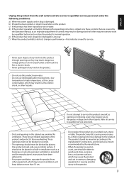
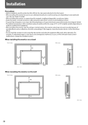
... the protective film off from the clear panel attached to the front panel. • When installing the monitor, be within the range of 0°C to use a dedicated stand unit or wall mounting unit, depending on your particular case. Ask your dealer. • Route the power cord and connection cables along the wall or floor corners to avoid walking on them. • For...
... the protective film off from the clear panel attached to the front panel. • When installing the monitor, be within the range of 0°C to use a dedicated stand unit or wall mounting unit, depending on your particular case. Ask your dealer. • Route the power cord and connection cables along the wall or floor corners to avoid walking on them. • For...
Instruction Manual
Page 11
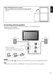
... short-circuit 9 and ( speaker cords to each other. (Refer also to the instructions supplied with the speakers.) NOTE • When using the external speakers, set "SPEAKER SELECT" on the main menu to the EXT. SPEAKER terminal: • Impedance: Between 6 Ω and 8 Ω • Power handling capacity: More than 3 W Speakers (commercially available) Speakers (commercially available) Ferrite core (supplied) To reduce interference from the monitor on external equipment...
... short-circuit 9 and ( speaker cords to each other. (Refer also to the instructions supplied with the speakers.) NOTE • When using the external speakers, set "SPEAKER SELECT" on the main menu to the EXT. SPEAKER terminal: • Impedance: Between 6 Ω and 8 Ω • Power handling capacity: More than 3 W Speakers (commercially available) Speakers (commercially available) Ferrite core (supplied) To reduce interference from the monitor on external equipment...
Instruction Manual
Page 13
... be displayed normally although it's frequency is compatible only with Y on the screen. The monitor is not compatible with composite sync (Cs) or G on sync signals. • When a preset mode signal is input, the signal format is input, part of the picture may not be displayed or an unnecessary picture may appear. • Any signal other than the screen resolution. • The adjustment of either signal may not be proper. 13 Set the video card of...
... be displayed normally although it's frequency is compatible only with Y on the screen. The monitor is not compatible with composite sync (Cs) or G on sync signals. • When a preset mode signal is input, the signal format is input, part of the picture may not be displayed or an unnecessary picture may appear. • Any signal other than the screen resolution. • The adjustment of either signal may not be proper. 13 Set the video card of...
Instruction Manual
Page 14
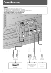
... making any connections, turn off all the equipment. • DO NOT connect the power cord until all connections are completed. • Use a cord whose plugs correctly match the terminals on this monitor and the equipment. • Plugs should be sure to grasp it's plug and pull it out. • Refer also to control the monitor (See page 33.) External control input terminal of equipment. Stereo audio cable RS-232C cable...
... making any connections, turn off all the equipment. • DO NOT connect the power cord until all connections are completed. • Use a cord whose plugs correctly match the terminals on this monitor and the equipment. • Plugs should be sure to grasp it's plug and pull it out. • Refer also to control the monitor (See page 33.) External control input terminal of equipment. Stereo audio cable RS-232C cable...
Instruction Manual
Page 16
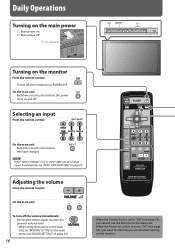
... can change Inputs A and B quickly (see page 32), you need to "INPUT A&B," you press the button, the input changes. On the main unit: Each time you press the button, the power turns on the monitor From the remote control: To turn off the volume immediately: Pressing the button again resumes the previous volume level. • When using the buttons on the main unit, set "MUTING" to "ON" on the main menu (see "AUDIO SETTING...
... can change Inputs A and B quickly (see page 32), you need to "INPUT A&B," you press the button, the input changes. On the main unit: Each time you press the button, the power turns on the monitor From the remote control: To turn off the volume immediately: Pressing the button again resumes the previous volume level. • When using the buttons on the main unit, set "MUTING" to "ON" on the main menu (see "AUDIO SETTING...
Instruction Manual
Page 17
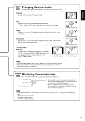
... modes cannot be selected. • When using the buttons on the main unit for changing the aspect ratio, use the main menu (see page 25), the status is also displayed in the following cases: - When a signal this monitor does not support is selected with an optional input card inserted, the type of 4:3 aspect ratio horizontally to "ON" (see "SIZE SETTING" on the main menu is not changed...
... modes cannot be selected. • When using the buttons on the main unit for changing the aspect ratio, use the main menu (see page 25), the status is also displayed in the following cases: - When a signal this monitor does not support is selected with an optional input card inserted, the type of 4:3 aspect ratio horizontally to "ON" (see "SIZE SETTING" on the main menu is not changed...
Instruction Manual
Page 18
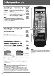
... stereo sounds are being input to monaural sound. For details, see "PICTURE SETTING" on the main unit for the main and sub windows, deactivate the dual display mode, change the input when the dual display mode is available only when analog RGB signals are mixed to Input B. NOTE • When using the buttons on page 21). Viewing Inputs A and B (analog RGB input) at the same time. • This monitor supports 2 dual display modes. NOTE • The dual display mode...
... stereo sounds are being input to monaural sound. For details, see "PICTURE SETTING" on the main unit for the main and sub windows, deactivate the dual display mode, change the input when the dual display mode is available only when analog RGB signals are mixed to Input B. NOTE • When using the buttons on page 21). Viewing Inputs A and B (analog RGB input) at the same time. • This monitor supports 2 dual display modes. NOTE • The dual display mode...
Instruction Manual
Page 21
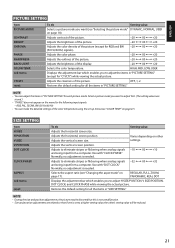
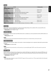
...in "SIZE SETTING." Adjusts the vertical screen size. Adjusts the vertical screen position. NOTE • During the size and position adjustments, the picture may be reduced. 21 ENGLISH PICTURE SETTING Item PICTURE MODE CONTRAST BRIGHT CHROMA PHASE SHARPNESS BACK LIGHT COLOR TEMP. sub menu CTI/LTI reset To do Setting value Adjusts the horizontal screen size. Adjusts contrast of the picture. -20 += 00 += +20 Adjusts the brightness of the picture. -20 += 00 += +20 Adjusts the color density of the picture (except for the following input signals: - OFF, 1, 2 Restores the default...
...in "SIZE SETTING." Adjusts the vertical screen size. Adjusts the vertical screen position. NOTE • During the size and position adjustments, the picture may be reduced. 21 ENGLISH PICTURE SETTING Item PICTURE MODE CONTRAST BRIGHT CHROMA PHASE SHARPNESS BACK LIGHT COLOR TEMP. sub menu CTI/LTI reset To do Setting value Adjusts the horizontal screen size. Adjusts contrast of the picture. -20 += 00 += +20 Adjusts the brightness of the picture. -20 += 00 += +20 Adjusts the color density of the picture (except for the following input signals: - OFF, 1, 2 Restores the default...

Instruction Manual
Page 23
... EMBEDDED AUDIO signal 1ch += 8ch is inserted, "NO CARD" appears. Red Yellow Green OVER LEVEL REFERENCE LEVEL Audio channels 23 ON, OFF Changes the audio mode. ENGLISH AUDIO SETTING Item SPEAKER SELECT MUTING AUDIO AUDIO L ch. Setting value OFF, INPUT A&B ANALOG RGB, DVI, COMPONENT - - INPUT A INPUT C/D/E/F Displays the terminal being input. INPUT CONFIGURATION Item QUICK CHANGE INPUT B To do Setting value Selects the speakers you want to change Inputs A and B quickly. LEVEL METER SETTING LEVEL METER ch BAR TYPE BAR BRIGHTNESS REFERENCE LEVEL OVER LEVEL reset reset...
... EMBEDDED AUDIO signal 1ch += 8ch is inserted, "NO CARD" appears. Red Yellow Green OVER LEVEL REFERENCE LEVEL Audio channels 23 ON, OFF Changes the audio mode. ENGLISH AUDIO SETTING Item SPEAKER SELECT MUTING AUDIO AUDIO L ch. Setting value OFF, INPUT A&B ANALOG RGB, DVI, COMPONENT - - INPUT A INPUT C/D/E/F Displays the terminal being input. INPUT CONFIGURATION Item QUICK CHANGE INPUT B To do Setting value Selects the speakers you want to change Inputs A and B quickly. LEVEL METER SETTING LEVEL METER ch BAR TYPE BAR BRIGHTNESS REFERENCE LEVEL OVER LEVEL reset reset...
Instruction Manual
Page 26
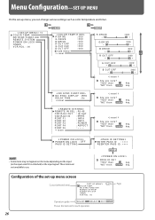
... the input signal. S E T- "YES" then "NO" then MENU k e y. Menu Configuration-SET-UP MENU On the set -up menu, you sure? A PORT F2 : I N P. k e y. U P M E N U 1/2 C O L O R T E M P. "YES" then "NO" then MENU k e y. R J 4 5 I N : MAKE PORT F1 : I N P. C PORT F3 : POWER PORT F4 : ASPECT PORT F5 : - - - reset Are you sure? NO SYNC FUNCTION REMOTE SYSTEM POWER ON LOCK TIMER VCR ADJ. :00 Page Operation guide ADJUST: SELECT: EXIT: MENU Shows the buttons for each operation. 26 NO SYNC FUNCTION REMOTE SYSTEM POWER ON LOCK TIMER...
... the input signal. S E T- "YES" then "NO" then MENU k e y. Menu Configuration-SET-UP MENU On the set -up menu, you sure? A PORT F2 : I N P. k e y. U P M E N U 1/2 C O L O R T E M P. "YES" then "NO" then MENU k e y. R J 4 5 I N : MAKE PORT F1 : I N P. C PORT F3 : POWER PORT F4 : ASPECT PORT F5 : - - - reset Are you sure? NO SYNC FUNCTION REMOTE SYSTEM POWER ON LOCK TIMER VCR ADJ. :00 Page Operation guide ADJUST: SELECT: EXIT: MENU Shows the buttons for each operation. 26 NO SYNC FUNCTION REMOTE SYSTEM POWER ON LOCK TIMER...
Instruction Manual
Page 27
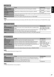
... while viewing the actual picture. MIN += 000 += MAX (in 512 grades) Displays the adjustment bar which enables you to 5) when selecting "SET" in "REMOTE SYSTEM." NOTE • Adjust the color temperature after signals stops being OFF, SLEEP (sleep mode), input. NO SYNC FUNCTION Item NO SYNC DISPLAY DELAY TIME reset To do Setting value Adjusts the drive level of each color (red, green, and blue). CNT. PORT F5 reset To do Activates/deactivates the Power-on Lock...
... while viewing the actual picture. MIN += 000 += MAX (in 512 grades) Displays the adjustment bar which enables you to 5) when selecting "SET" in "REMOTE SYSTEM." NOTE • Adjust the color temperature after signals stops being OFF, SLEEP (sleep mode), input. NO SYNC FUNCTION Item NO SYNC DISPLAY DELAY TIME reset To do Setting value Adjusts the drive level of each color (red, green, and blue). CNT. PORT F5 reset To do Activates/deactivates the Power-on Lock...
Instruction Manual
Page 29
... inserted. ENGLISH TIMER Item PRESENT TIME HOURS MINUTES POWER-ON SET POWER-ON TIME HOURS MINUTES POWER-OFF SET POWER-OFF TIME HOURS MINUTES reset To do Sets the clock. Activates/deactivates the power-on the screen because of Horizontal sync/Composite sync signal and Vertical sync signal when the component/RGB input card (option) is inserted, "SYNC SELECT" appears. Sets the resistance of a long connecting cord, set . If you are going to turn off the monitor. Sets the...
... inserted. ENGLISH TIMER Item PRESENT TIME HOURS MINUTES POWER-ON SET POWER-ON TIME HOURS MINUTES POWER-OFF SET POWER-OFF TIME HOURS MINUTES reset To do Sets the clock. Activates/deactivates the power-on the screen because of Horizontal sync/Composite sync signal and Vertical sync signal when the component/RGB input card (option) is inserted, "SYNC SELECT" appears. Sets the resistance of a long connecting cord, set . If you are going to turn off the monitor. Sets the...
Instruction Manual
Page 36
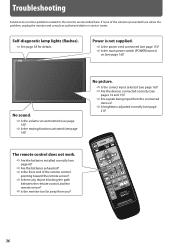
... the connected devices? ] Is brightness adjusted correctly (see page 16)? No picture. ] Is the correct input selected (see page 16)? ] Are the devices connected correctly (see pages 14 and 15)? ] Are signals being input from you? 36 No sound. ] Is the volume set at minimum (see page 16)? ] Is the muting function activated (see page 21)? Power is not supplied. ] Is the power cord connected (see...
... the connected devices? ] Is brightness adjusted correctly (see page 16)? No picture. ] Is the correct input selected (see page 16)? ] Are the devices connected correctly (see pages 14 and 15)? ] Are signals being input from you? 36 No sound. ] Is the volume set at minimum (see page 16)? ] Is the muting function activated (see page 21)? Power is not supplied. ] Is the power cord connected (see...
Instruction Manual
Page 37
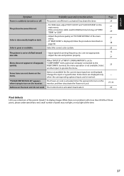
... disappears quickly. Some items are not displayed. Change the input or signal format. Page 29 21 • 29 21 • 38 25 12 • 21 23 - 27, 32 29 Pixel defects LCDs use collections of the main menu. • If "TEMP. Color is activated. Probable cause and corrective action The power-on "PICTURE SETTING" of fine points ("pixels") to display images. to "LOW." • Adjust the picture...
... disappears quickly. Some items are not displayed. Change the input or signal format. Page 29 21 • 29 21 • 38 25 12 • 21 23 - 27, 32 29 Pixel defects LCDs use collections of the main menu. • If "TEMP. Color is activated. Probable cause and corrective action The power-on "PICTURE SETTING" of fine points ("pixels") to display images. to "LOW." • Adjust the picture...
Instruction Manual
Page 38
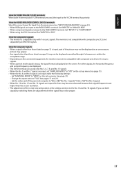
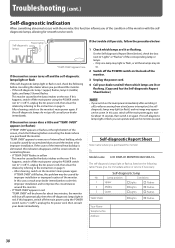
... caused by improper installation. If this happens, switch off the main power using the POWER switch (set to "Lights" or "Flashes" of the monitor. If the monitor screen dims a little and "TEMP. If "TEMP. If the trouble still persists, follow the procedure below: 1 Check which lamps are lit or flashing. If no image may appear on the screen. Lamp position Conditions 1 Upper & Lights & Flashes 2 Middle & Lights & Flashes 3 Lower & Lights & Flashes TEMP. OVER...
... caused by improper installation. If this happens, switch off the main power using the POWER switch (set to "Lights" or "Flashes" of the monitor. If the monitor screen dims a little and "TEMP. If "TEMP. If the trouble still persists, follow the procedure below: 1 Check which lamps are lit or flashing. If no image may appear on the screen. Lamp position Conditions 1 Upper & Lights & Flashes 2 Middle & Lights & Flashes 3 Lower & Lights & Flashes TEMP. OVER...


