Instructions
Page 1
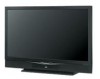
Keep the carton and original packaging for future reference. Keep this guide. Model Number: Serial Number: LCT1833-001A-A 0105TNH-II-IM Staple your television (located at the rear of this user's guide in a convenient place for future use. Projection Television Users Guide For Models: HD-70G886 HD-61Z886 HD-61Z786 Illustration of HD-70G886 and RM-C14G Important Note: In the spaces below, enter the model and serial number of your sales receipt or invoice to the inside cover of the television cabinet).
Keep the carton and original packaging for future reference. Keep this guide. Model Number: Serial Number: LCT1833-001A-A 0105TNH-II-IM Staple your television (located at the rear of this user's guide in a convenient place for future use. Projection Television Users Guide For Models: HD-70G886 HD-61Z886 HD-61Z786 Illustration of HD-70G886 and RM-C14G Important Note: In the spaces below, enter the model and serial number of your sales receipt or invoice to the inside cover of the television cabinet).
Instructions
Page 2
...persons. CAUTION: TO INSURE PERSONAL SAFETY, OBSERVE THE FOLLOWING RULES REGARDING THE USE OF THIS UNIT. 1. Avoid damaging the AC plug and power cord. 3. Refer servicing to repair it yourself or remove the rear cover. The exclamation point within the product's enclosure that contains a small ... community due to prevent blade exposure. Changes or modifications not approved by JVC could void the warranty. * When you don't use this TV set for your safety. * To prevent electric shock do not use this polarized plug with arrowhead symbol, within an equilateral triangle is intended to...
...persons. CAUTION: TO INSURE PERSONAL SAFETY, OBSERVE THE FOLLOWING RULES REGARDING THE USE OF THIS UNIT. 1. Avoid damaging the AC plug and power cord. 3. Refer servicing to repair it yourself or remove the rear cover. The exclamation point within the product's enclosure that contains a small ... community due to prevent blade exposure. Changes or modifications not approved by JVC could void the warranty. * When you don't use this TV set for your safety. * To prevent electric shock do not use this polarized plug with arrowhead symbol, within an equilateral triangle is intended to...
Instructions
Page 3
...blades with dry cloth. 7) Do not block any heat sources such as radiators, heat registers, stoves, or other limited viewing uses only unless otherwise authorized by U.S. Use of this apparatus near any ventilation openings. IMPORTANT SAFETY INSTRUCTIONS 1) Read these instructions. 2) Keep these instructions. 3) Heed all ...being walked on or pinched particularly at plugs, convenience receptacles, and the point where they exit from the apparatus. 11) Only use caution when moving the cart/apparatus combination to avoid injury from tip-over. 3 patents and other . A grounding type plug has...
...blades with dry cloth. 7) Do not block any heat sources such as radiators, heat registers, stoves, or other limited viewing uses only unless otherwise authorized by U.S. Use of this apparatus near any ventilation openings. IMPORTANT SAFETY INSTRUCTIONS 1) Read these instructions. 2) Keep these instructions. 3) Heed all ...being walked on or pinched particularly at plugs, convenience receptacles, and the point where they exit from the apparatus. 11) Only use caution when moving the cart/apparatus combination to avoid injury from tip-over. 3 patents and other . A grounding type plug has...

Instructions
Page 4
... with the instructions, may cause harmful interference to radio communications. When installing this TV, distance recommendations must be maintained between the equipment and receiver. - The TV will not occur in a residential installation. This equipment generates, uses and can be placed on the floor so as inside a tightly enclosed area ... to keep cords out of the way. - Do not tilt the TV towards the left or right, or towards the back. - Ensure that to which can radiate radio frequency energy and, if not installed and used in any way, such as power-supply cord or plug is no ...
... with the instructions, may cause harmful interference to radio communications. When installing this TV, distance recommendations must be maintained between the equipment and receiver. - The TV will not occur in a residential installation. This equipment generates, uses and can be placed on the floor so as inside a tightly enclosed area ... to keep cords out of the way. - Do not tilt the TV towards the left or right, or towards the back. - Ensure that to which can radiate radio frequency energy and, if not installed and used in any way, such as power-supply cord or plug is no ...
Instructions
Page 5
... coating. Do not push or hit the screen. Then wipe immediately after with a soft cloth. This could cause scratches on the TV's surface. • DO NOT rub or scrub the TV harshly. You can add a few drops of mild liquid detergent to the water to help remove spots of oily dirt. •...; DO NOT allow liquid to enter the TV through the ventilation slots. • DO NOT use strong or abrasive cleaners on the TV. • DO NOT spray liquids or cleaners directly on the screen surface and image distortions. 5 Caring for the...
... coating. Do not push or hit the screen. Then wipe immediately after with a soft cloth. This could cause scratches on the TV's surface. • DO NOT rub or scrub the TV harshly. You can add a few drops of mild liquid detergent to the water to help remove spots of oily dirt. •...; DO NOT allow liquid to enter the TV through the ventilation slots. • DO NOT use strong or abrasive cleaners on the TV. • DO NOT spray liquids or cleaners directly on the screen surface and image distortions. 5 Caring for the...
Instructions
Page 6
...uses the high-quality HD-ILA projection system. Do not block the air intake holes behind the speaker grills. 3. It is recommended that you read the safety cautions and information about it . Immediately after the cooling process has completed. There are summarized below . After the cooling has been performed for purchasing JVC... life of the device and important information which the TV is performed for approximately 1 minute at their full brightness. Once again, thank you for a long time is being performed. Before using your television in order to be operated while the...
...uses the high-quality HD-ILA projection system. Do not block the air intake holes behind the speaker grills. 3. It is recommended that you read the safety cautions and information about it . Immediately after the cooling process has completed. There are summarized below . After the cooling has been performed for purchasing JVC... life of the device and important information which the TV is performed for approximately 1 minute at their full brightness. Once again, thank you for a long time is being performed. Before using your television in order to be operated while the...
Instructions
Page 7
... This unit has an air duct for a long period of burns. ILA element characteristics Do not project still pictures or pictures that have still segments for cooling. This is called condensation. In this television... off repeatedly in a short amount of water may become dirty. Also, take care to keep the TV on for details on the lamp glass, there is moved from fingers on how to a ... device, or when using the television. 12. Do not touch the lamp glass If the lamp is connected directly to the wall socket, and not to change. Do not open the rear cabinet. 13. Be...
... This unit has an air duct for a long period of burns. ILA element characteristics Do not project still pictures or pictures that have still segments for cooling. This is called condensation. In this television... off repeatedly in a short amount of water may become dirty. Also, take care to keep the TV on for details on the lamp glass, there is moved from fingers on how to a ... device, or when using the television. 12. Do not touch the lamp glass If the lamp is connected directly to the wall socket, and not to change. Do not open the rear cabinet. 13. Be...
Instructions
Page 8
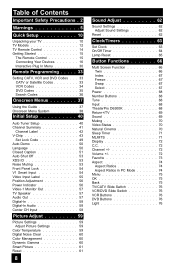
...TV Models 12 TV Remote Control 14 Getting Started 15 The Remote Control 15 Connecting Your Devices 16 Interactive Plug In Menu 30 Remote Programming . . . . . 33 Setting CATV, VCR and DVD Codes . . . 33 CATV or Satellite Codes 33 VCR Codes 34 DVD Codes 35 Search Codes 36 Onscreen Menus 37 Using... 59 Picture Settings 59 Adjust Picture Settings 59 Color Temperature 59 Digital Noise Clear 60 Color Management 60 Dynamic Gamma 60 Smart Picture 61 Reset 61 8 Sound Adjust 62 Sound Settings 62 Adjust Sound Settings 62 Reset 62 Clock/Timers 63 Set Clock 63 On/Off Timer 64 ...
...TV Models 12 TV Remote Control 14 Getting Started 15 The Remote Control 15 Connecting Your Devices 16 Interactive Plug In Menu 30 Remote Programming . . . . . 33 Setting CATV, VCR and DVD Codes . . . 33 CATV or Satellite Codes 33 VCR Codes 34 DVD Codes 35 Search Codes 36 Onscreen Menus 37 Using... 59 Picture Settings 59 Adjust Picture Settings 59 Color Temperature 59 Digital Noise Clear 60 Color Management 60 Dynamic Gamma 60 Smart Picture 61 Reset 61 8 Sound Adjust 62 Sound Settings 62 Adjust Sound Settings 62 Reset 62 Clock/Timers 63 Set Clock 63 On/Off Timer 64 ...

Instructions
Page 11
... Audio Cables Used to connect JVC AV CompuLink capable components for an automated home theater. AV CompuLink Cable Used to make these connections you will use with S-Video VCRs, Camcorders and DVD players. If you're anxious to start using your new television's many great features. Used to connect audio... right away, a quick setup guide follows on the next few pages. 11 Coaxial Cables Used to connect an external antenna or cable TV system to your TV. Quick Setup Unpacking your TV Once you have unpacked your television, the next step is to connect it to your antenna...
... Audio Cables Used to connect JVC AV CompuLink capable components for an automated home theater. AV CompuLink Cable Used to make these connections you will use with S-Video VCRs, Camcorders and DVD players. If you're anxious to start using your new television's many great features. Used to connect audio... right away, a quick setup guide follows on the next few pages. 11 Coaxial Cables Used to connect an external antenna or cable TV system to your TV. Quick Setup Unpacking your TV Once you have unpacked your television, the next step is to connect it to your antenna...
Instructions
Page 12
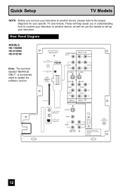
Rear Panel Diagram MODELS: HD-70G886 HD-61Z886 HD-61Z786 Note: The terminal labeled "SERVICE ONLY", is exclusively used to set up your specific TV and remote. PATENTS 6,183,091 6,419,362 12 SERVICE ONLY ATSC /DIGITAL CABLE IN I DIGITAL IN AV COMPULINK III VIDEO (DIGITAL) _ ...S-VIDEO VIDEO L AUDIO PC IN (D-SUB) L AUDIO OUTPUT 75Ω (VHF/UHF) R R MONITOR /REC OUT LICENSED UNDER THE FOLLOWING U.S. Quick Setup TV Models NOTE: Before you in understanding how to connect your television to another device, please refer to the proper diagrams for your television. These will...
Rear Panel Diagram MODELS: HD-70G886 HD-61Z886 HD-61Z786 Note: The terminal labeled "SERVICE ONLY", is exclusively used to set up your specific TV and remote. PATENTS 6,183,091 6,419,362 12 SERVICE ONLY ATSC /DIGITAL CABLE IN I DIGITAL IN AV COMPULINK III VIDEO (DIGITAL) _ ...S-VIDEO VIDEO L AUDIO PC IN (D-SUB) L AUDIO OUTPUT 75Ω (VHF/UHF) R R MONITOR /REC OUT LICENSED UNDER THE FOLLOWING U.S. Quick Setup TV Models NOTE: Before you in understanding how to connect your television to another device, please refer to the proper diagrams for your television. These will...
Instructions
Page 13
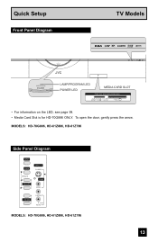
L/MONO R AUDIO MODELS: HD-70G886, HD-61Z886, HD-61Z786 13 MODELS: HD-70G886, HD-61Z886, HD-61Z786 Side Panel Diagram INPUT MENU INPUT 4 S-VIDEO OPERATE + CHANNEL - OVER VIDEO + VOLUME - Quick Setup Front Panel Diagram TV Models LAMP/PROGRAM POWER LAMP/PROGRAM POWER LAMP/PROGRAM LED POWER LED MEDIA CARD SLOT Close door when using media cards SD/ MMC MEMORY xD-Picture STICK Card COMPACT FLASH • For information on the LED, see page 99. • Media Card Slot is for HD-70G886 ONLY. To open the door, gently press the arrow.
L/MONO R AUDIO MODELS: HD-70G886, HD-61Z886, HD-61Z786 13 MODELS: HD-70G886, HD-61Z886, HD-61Z786 Side Panel Diagram INPUT MENU INPUT 4 S-VIDEO OPERATE + CHANNEL - OVER VIDEO + VOLUME - Quick Setup Front Panel Diagram TV Models LAMP/PROGRAM POWER LAMP/PROGRAM POWER LAMP/PROGRAM LED POWER LED MEDIA CARD SLOT Close door when using media cards SD/ MMC MEMORY xD-Picture STICK Card COMPACT FLASH • For information on the LED, see page 99. • Media Card Slot is for HD-70G886 ONLY. To open the door, gently press the arrow.
Instructions
Page 14
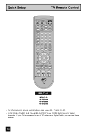
... CHANNEL SUB LIGHT MUTING CH GUIDE VOL OK VOL CH MENU VCR CHANNEL PREV NEXT BACK VCR DVD POWER TV VCR REW PLAY FF REC STOP PAUSE OPEN CLOSE STILL PAUSE RM-C14G RM-C14G MODELS: HD-70G886 HD-61Z886 HD-61Z786 • For information .... • i.LINK MENU, TIMER, SUB CHANNEL, FAVORITE and GUIDE buttons are for digital channels. If your TV is connected to an ATSC antenna or Digital Cable, you can use these buttons. 14 Quick Setup TV Remote Control TV CATV VCR DVD POWER ASPECT MULTI SCREEN TWIN INDEX SELECT SLEEP FREEZE SWAP ML/MTS DISPLAY...
... CHANNEL SUB LIGHT MUTING CH GUIDE VOL OK VOL CH MENU VCR CHANNEL PREV NEXT BACK VCR DVD POWER TV VCR REW PLAY FF REC STOP PAUSE OPEN CLOSE STILL PAUSE RM-C14G RM-C14G MODELS: HD-70G886 HD-61Z886 HD-61Z786 • For information .... • i.LINK MENU, TIMER, SUB CHANNEL, FAVORITE and GUIDE buttons are for digital channels. If your TV is connected to an ATSC antenna or Digital Cable, you can use these buttons. 14 Quick Setup TV Remote Control TV CATV VCR DVD POWER ASPECT MULTI SCREEN TWIN INDEX SELECT SLEEP FREEZE SWAP ML/MTS DISPLAY...

Instructions
Page 15
...and are turning on any of these steps, please consult other sections of the remote can operate your remote control, you first need to begin using JVC's Hyperscan feature, press and hold CH+ or CH-. The POWER LED will zip by pressing the POWER button at the top right corner ...five channels per second. Insert two batteries (included) carefully noting the "+" and "-" markings, placing the "-" end in menu appears. • Make sure the TV/CATV switch is the first time you take longer than three minutes, the remote control codes for your remote control to control a DVD player. The...
...and are turning on any of these steps, please consult other sections of the remote can operate your remote control, you first need to begin using JVC's Hyperscan feature, press and hold CH+ or CH-. The POWER LED will zip by pressing the POWER button at the top right corner ...five channels per second. Insert two batteries (included) carefully noting the "+" and "-" markings, placing the "-" end in menu appears. • Make sure the TV/CATV switch is the first time you take longer than three minutes, the remote control codes for your remote control to control a DVD player. The...
Instructions
Page 16
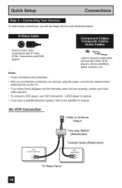
...or Antenna Output ATSC /DIGITAL CABLE IN I IN Two-way Splitter OUT OUT (Attachment) Coaxial Cable (Attachment) 75Ω (VHF/UHF) TV Rear Panel 16 Connecting Your Devices To make video connections with S-Video VCRs, Camcorders and DVD players. A DVD player is optional • If you... television system, refer to connect audio/video devices like the ones illustrated below. S-Video Cable Component Cables Composite Cables Audio Cables Used to make these connections, you follow these diagrams and the television does not work properly, contact your devices, plug the power cord...
...or Antenna Output ATSC /DIGITAL CABLE IN I IN Two-way Splitter OUT OUT (Attachment) Coaxial Cable (Attachment) 75Ω (VHF/UHF) TV Rear Panel 16 Connecting Your Devices To make video connections with S-Video VCRs, Camcorders and DVD players. A DVD player is optional • If you... television system, refer to connect audio/video devices like the ones illustrated below. S-Video Cable Component Cables Composite Cables Audio Cables Used to make these connections, you follow these diagrams and the television does not work properly, contact your devices, plug the power cord...
Instructions
Page 20
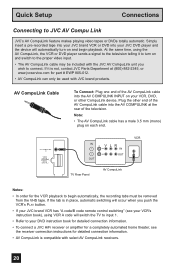
...will occur when you wish to the proper video input. • The AV CompuLink cable may be used with JVC brand products. If the tab is not, contact JVC Parts Department at the rear of the AV CompuLink cable into the AV COMPULINK INPUT on and switch to connect. AV CompuLink Cable...with select AV CompuLink receivers. 20 Plug the other CompuLink device. Simply insert a pre-recorded tape into your JVC brand VCR or DVD into your JVC DVD player and the device will switch the TV to input 1. • Refer to your DVD instruction book for detailed connection information. • To connect...
...will occur when you wish to the proper video input. • The AV CompuLink cable may be used with JVC brand products. If the tab is not, contact JVC Parts Department at the rear of the AV CompuLink cable into the AV COMPULINK INPUT on and switch to connect. AV CompuLink Cable...with select AV CompuLink receivers. 20 Plug the other CompuLink device. Simply insert a pre-recorded tape into your JVC brand VCR or DVD into your JVC DVD player and the device will switch the TV to input 1. • Refer to your DVD instruction book for detailed connection information. • To connect...
Instructions
Page 21
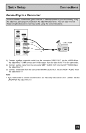
...VIDEO + VOLUME - Note: • If your television by using the same instructions. CAMCORDER 1) Connect a yellow composite cable from the camcorder VIDEO OUT, into the VIDEO IN on the side of the TV, OR connect an S-Video cable from the side of the TV to the camcorder. 2) Connect a white cable from the ...to your camcorder is a mono sound model it to the L/MONO on the side of the TV. 21 OR - Connect it will have only one AUDIO OUT. L/MONO R AUDIO - You can also connect these using the television's rear input jacks, using the side input jacks (Input 4) located on the side of the...
...VIDEO + VOLUME - Note: • If your television by using the same instructions. CAMCORDER 1) Connect a yellow composite cable from the camcorder VIDEO OUT, into the VIDEO IN on the side of the TV, OR connect an S-Video cable from the side of the TV to the camcorder. 2) Connect a white cable from the ...to your camcorder is a mono sound model it to the L/MONO on the side of the TV. 21 OR - Connect it will have only one AUDIO OUT. L/MONO R AUDIO - You can also connect these using the television's rear input jacks, using the side input jacks (Input 4) located on the side of the...

Instructions
Page 22
...theater system. 22 A center speaker in a movie theater is set in back of the TV to the RIGHT AUDIO INPUT on page 58. By using your amplifier's manual for more naturally. TV Rear Panel Front Front Surround CENTER CHANNEL INPUT L AUDIO R CENTER CHANNEL OUTPUT (VARIABLE OUTPUT) ...1) Connect the Pin cable from the center speaker. Notes: • Refer to your TV's speaker as the center speaker...
...theater system. 22 A center speaker in a movie theater is set in back of the TV to the RIGHT AUDIO INPUT on page 58. By using your amplifier's manual for more naturally. TV Rear Panel Front Front Surround CENTER CHANNEL INPUT L AUDIO R CENTER CHANNEL OUTPUT (VARIABLE OUTPUT) ...1) Connect the Pin cable from the center speaker. Notes: • Refer to your TV's speaker as the center speaker...
Instructions
Page 23
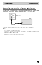
i.LINK IN/OUT S400(TS) TV Rear Panel OPTICAL OUT Digital Audio Amplifier 1) Connect the optical cable from the optical output. Quick Setup Connections Connecting to an amplifier using your optical output You can be PCM or Dolby Digital. The signal that is output can connect an amplifier that has an ... • Refer to your amplifier. 23 Notes: • This terminal can only output digital audio. • In order to the back of the TV to use the optical output connection, select PCM or Dolby Digital on using an optical digital cable from the back of the amplifier.
i.LINK IN/OUT S400(TS) TV Rear Panel OPTICAL OUT Digital Audio Amplifier 1) Connect the optical cable from the optical output. Quick Setup Connections Connecting to an amplifier using your optical output You can be PCM or Dolby Digital. The signal that is output can connect an amplifier that has an ... • Refer to your amplifier. 23 Notes: • This terminal can only output digital audio. • In order to the back of the TV to use the optical output connection, select PCM or Dolby Digital on using an optical digital cable from the back of the amplifier.

Instructions
Page 24
... the screen, the horizontal balance may be displayed on the back of a personal computer. • Use a HDMI to DVI cable (commercially available) in the Initial Setup menu to ANALOG. TV Rear Panel AUDIO OUT LR DTV Decoder DIGITAL OUT AV COMPULINK III VIDEO (DIGITAL) _ AUDIO (DIGITAL) ...television. • The digital-in terminal is not compatible with the picture signal of your TV in their digital form. Quick Setup Connections Connecting to a Digital TV Receiver By connecting a Digital TV Receiver, high definition pictures can be slightly shifted. Access the "DIGITAL-IN" in the ...
... the screen, the horizontal balance may be displayed on the back of a personal computer. • Use a HDMI to DVI cable (commercially available) in the Initial Setup menu to ANALOG. TV Rear Panel AUDIO OUT LR DTV Decoder DIGITAL OUT AV COMPULINK III VIDEO (DIGITAL) _ AUDIO (DIGITAL) ...television. • The digital-in terminal is not compatible with the picture signal of your TV in their digital form. Quick Setup Connections Connecting to a Digital TV Receiver By connecting a Digital TV Receiver, high definition pictures can be slightly shifted. Access the "DIGITAL-IN" in the ...
Instructions
Page 26
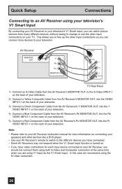
... have video connections for more devices to your television. In this case we recommend using the S-Video connection. 26 AV Receiver MONITOR OUT Y PB PR MONITOR OUT S-VIDEO OVER Y VIDEO L Pb I AUDIO I R Pr INPUT-1 TV Rear Panel 1) Connect an S-Video Cable from the AV Receiver's MONITOR OUT, to.... 4) Connect a Blue Component Cable from the AV Receiver's PB MONITOR OUT, into the Pr VIDEO INPUT-1 on your TV. Quick Setup Connections Connecting to an AV Receiver using your television's V1 Smart Input By connecting your AV Receiver to your television's V1 Smart Input, you are...
... have video connections for more devices to your television. In this case we recommend using the S-Video connection. 26 AV Receiver MONITOR OUT Y PB PR MONITOR OUT S-VIDEO OVER Y VIDEO L Pb I AUDIO I R Pr INPUT-1 TV Rear Panel 1) Connect an S-Video Cable from the AV Receiver's MONITOR OUT, to.... 4) Connect a Blue Component Cable from the AV Receiver's PB MONITOR OUT, into the Pr VIDEO INPUT-1 on your TV. Quick Setup Connections Connecting to an AV Receiver using your television's V1 Smart Input By connecting your AV Receiver to your television's V1 Smart Input, you are...


