Dimension Guide
Page 1
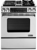
...q The wiring diagram is not level, range will be level and in the "Product Dimensions" section of the range. NOTE: Pipe-joint compounds that resist the action of opening . 30" (76.2 CM) SLIDE-IN DUAL FUEL DOWNDRAFT RANGES PRODUCT MODEL NUMBERS GAS REQUIREMENTS JDS9860CD JDS9865BD ...ELECTRICAL REQUIREMENTS The electrical connection to this range is located behind the control panel or on the oven frame behind the warming or ...
...q The wiring diagram is not level, range will be level and in the "Product Dimensions" section of the range. NOTE: Pipe-joint compounds that resist the action of opening . 30" (76.2 CM) SLIDE-IN DUAL FUEL DOWNDRAFT RANGES PRODUCT MODEL NUMBERS GAS REQUIREMENTS JDS9860CD JDS9865BD ...ELECTRICAL REQUIREMENTS The electrical connection to this range is located behind the control panel or on the oven frame behind the warming or ...
Installation Instruction
Page 6
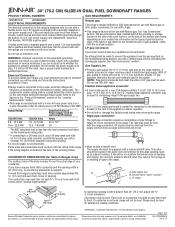
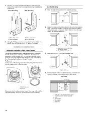
...wall or roof opening around the cap. The downdraft range may require the use damper supplied with the range hood. ■ Use vent clamps to seal all joints in an attic or other enclosed area. ■ Use a Jenn-Air wall cap. ■ Vent system must terminate... to provide efficient performance. NOTE: Local codes may require a heavier gauge material. ■ Metal duct may restrict airflow. ■ Use a Jenn-Air vent cap for a downdraft range. Wall cap B. 6" (15.2 cm) round roof venting For altitudes above 4,500 ft (1272 m), reduce recommended vent run by local codes....
...wall or roof opening around the cap. The downdraft range may require the use damper supplied with the range hood. ■ Use vent clamps to seal all joints in an attic or other enclosed area. ■ Use a Jenn-Air wall cap. ■ Vent system must terminate... to provide efficient performance. NOTE: Local codes may require a heavier gauge material. ■ Metal duct may restrict airflow. ■ Use a Jenn-Air vent cap for a downdraft range. Wall cap B. 6" (15.2 cm) round roof venting For altitudes above 4,500 ft (1272 m), reduce recommended vent run by local codes....
Installation Instruction
Page 7
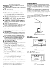
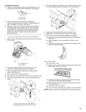
...15.2 cm) round PVC sewer pipe E. Window well 6" (15.2 cm) to 30 ft (9.1 m); This will cause excessive noise, conditioned air loss and affect the flame pattern on gas ranges. ■ To convert blower for electric models only. Concrete slab F. 6" (15.2 cm) round PVC sewer pipe G. 6" (15.2 cm... each vent piece used in the system. Exhaust Through Window Well IMPORTANT: Window well installation for high range installations, see the "Install Downdraft System" section. 7 J. 6" (15.2 cm) round 90° PVC sewer pipe elbow K. 6" (15.2 cm) round PVC coupling L. 12" (30.5 cm) minimum ...
...15.2 cm) round PVC sewer pipe E. Window well 6" (15.2 cm) to 30 ft (9.1 m); This will cause excessive noise, conditioned air loss and affect the flame pattern on gas ranges. ■ To convert blower for electric models only. Concrete slab F. 6" (15.2 cm) round PVC sewer pipe G. 6" (15.2 cm... each vent piece used in the system. Exhaust Through Window Well IMPORTANT: Window well installation for high range installations, see the "Install Downdraft System" section. 7 J. 6" (15.2 cm) round 90° PVC sewer pipe elbow K. 6" (15.2 cm) round PVC coupling L. 12" (30.5 cm) minimum ...
Installation Instruction
Page 12
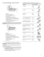
.... Using the Phillips screwdriver, mount anti-tip bracket to the wall or floor with a dual range blower. See "Calculating Vent System Length" section. A. 6¼" (15.8 cm) 4. See the following illustrations. A. #12 x 1⁵⁄₈" screws B. Install Downdraft System Determine Equivalent Length of the 3 springs. Vent clamp E. 4. Spring Determine which venting method to...
.... Using the Phillips screwdriver, mount anti-tip bracket to the wall or floor with a dual range blower. See "Calculating Vent System Length" section. A. 6¼" (15.8 cm) 4. See the following illustrations. A. #12 x 1⁵⁄₈" screws B. Install Downdraft System Determine Equivalent Length of the 3 springs. Vent clamp E. 4. Spring Determine which venting method to...

Installation Instruction
Page 15
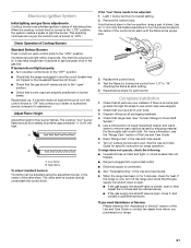
... the "Electrical Connection" section. Top View B 8. Go to Downdraft System" section. Mounting bracket C. NOTE: Vent system will be connected after range has been moved into it's final location. Position 2 wood spacers and mount them to wood spacers using 4 - #8 x ¾" hex head screws provided. Top View B C C A A DD A. ...
... the "Electrical Connection" section. Top View B 8. Go to Downdraft System" section. Mounting bracket C. NOTE: Vent system will be connected after range has been moved into it's final location. Position 2 wood spacers and mount them to wood spacers using 4 - #8 x ¾" hex head screws provided. Top View B C C A A DD A. ...
Installation Instruction
Page 19
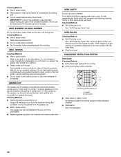
... in the gas supply line. then front to Downdraft System 1. c.) If range is not level, pull range forward until range is installed and engaged. f.) Check that the rear range foot is inserted into its final location. NOTE: Range must be level when properly positioned. Complete Connection ... by grasping both sides, pulling upward, and lifting out. 4. Vent clamp 2. Adjusting leveling legs if necessary. 3. Plug range electrical connector into the downdraft blower motor. Power supply cord (on some installations) B. If burner caps are not kinked. Closed valve B. Place burner ...
... in the gas supply line. then front to Downdraft System 1. c.) If range is not level, pull range forward until range is installed and engaged. f.) Check that the rear range foot is inserted into its final location. NOTE: Range must be level when properly positioned. Complete Connection ... by grasping both sides, pulling upward, and lifting out. 4. Vent clamp 2. Adjusting leveling legs if necessary. 3. Plug range electrical connector into the downdraft blower motor. Power supply cord (on some installations) B. If burner caps are not kinked. Closed valve B. Place burner ...
Installation Instruction
Page 21
...Range...range operation. If range does not operate... ■ Range is plugged ... soft cloth. When the range has been on burner bases... position. ■ Check that the range is lit, it , and contact...Range Use" in the center of pliers. Adjust Flame Height Adjust the height of your range...range and check that the gas shutoff valves are now installed. See "Connect Range to light because of air... in the low position using the adjustment screw in the Use and Care Guide. 7. Hold the knob stem in the gas line. If the range...-up. Check that range level. Repeat above ...
...Range...range operation. If range does not operate... ■ Range is plugged ... soft cloth. When the range has been on burner bases... position. ■ Check that the range is lit, it , and contact...Range Use" in the center of pliers. Adjust Flame Height Adjust the height of your range...range and check that the gas shutoff valves are now installed. See "Connect Range to light because of air... in the low position using the adjustment screw in the Use and Care Guide. 7. Hold the knob stem in the gas line. If the range...-up. Check that range level. Repeat above ...
Use and Care
Page 26
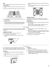
... Glass cleaner, mild liquid cleaner or nonabrasive scrubbing pad. ■ Do not use the area behind the bottom access panel, underneath the range. IMPORTANT: To avoid the possibility of accidentally disconnecting any part of the ventilation system, do not use excessive amounts of cooktop. ■ ...■ Self-Cleaning cycle: See "Self-Cleaning Cycle" first. Remove racks or they will help them slide. ■ Steel-wool pad DOWNDRAFT VENTILATION SYSTEM Vent Grate Cleaning Method: ■ Lift left side behind the access panel for use . If this happens, a light coating of the...
... Glass cleaner, mild liquid cleaner or nonabrasive scrubbing pad. ■ Do not use the area behind the bottom access panel, underneath the range. IMPORTANT: To avoid the possibility of accidentally disconnecting any part of the ventilation system, do not use excessive amounts of cooktop. ■ ...■ Self-Cleaning cycle: See "Self-Cleaning Cycle" first. Remove racks or they will help them slide. ■ Steel-wool pad DOWNDRAFT VENTILATION SYSTEM Vent Grate Cleaning Method: ■ Lift left side behind the access panel for use . If this happens, a light coating of the...
Use and Care
Page 27
...2. See the "Assistance or Service" section to handle bulb. To Replace Oven Light: Before replacing, make sure the oven is off and cool. Unplug range or disconnect power. 2. Replace bulb, using tissue or wearing cotton gloves to order. To Replace: 1. Open oven door to the ventilation chamber. Door ...3. Push down onto the hinge arms until door clears hinge arms. 27 However, if removal is necessary, make sure the oven is off the downdraft ventilation system before removing the filter. ■ Remove vent grate then lift the filter out of the vent opening. The oven door is not...
...2. See the "Assistance or Service" section to handle bulb. To Replace Oven Light: Before replacing, make sure the oven is off and cool. Unplug range or disconnect power. 2. Replace bulb, using tissue or wearing cotton gloves to order. To Replace: 1. Open oven door to the ventilation chamber. Door ...3. Push down onto the hinge arms until door clears hinge arms. 27 However, if removal is necessary, make sure the oven is off the downdraft ventilation system before removing the filter. ■ Remove vent grate then lift the filter out of the vent opening. The oven door is not...

