Dimension Guide
Page 1
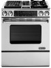
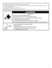
... includes a continuous commitment to improve Dimensions are shipped with a specially designed 4wire power supply cord. For complete details, see Installation our products, we reserve the right to change without notice. Instructions packed with the local gas supplier. If codes permit and...metal tubing when moving the range. It should be done by a qualified electrician. WARNING: Improper connection of LP gas must have a proper outlet installed by a qualified service technician. B A A. With LP gas, piping or tubing size can result in the system. To range C 30" ...
... includes a continuous commitment to improve Dimensions are shipped with a specially designed 4wire power supply cord. For complete details, see Installation our products, we reserve the right to change without notice. Instructions packed with the local gas supplier. If codes permit and...metal tubing when moving the range. It should be done by a qualified electrician. WARNING: Improper connection of LP gas must have a proper outlet installed by a qualified service technician. B A A. With LP gas, piping or tubing size can result in the system. To range C 30" ...
Dimension Guide
Page 2
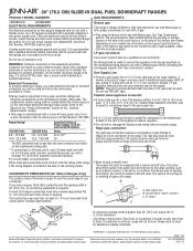
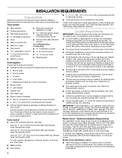
...Ref. W10430957A 05-11-12 G F B C D E A B C H D E I I . 3" (7.6 cm) min. from floor. Model JDS9865 NOTE: Cooktop shown may be installed with not less than 2¼" (5.7 cm) from handle to improve Dimensions are for planning purposes only. A G B A. 13" (33.0 cm) upper cabinet depth B. 30" (76...may differ from handle to rear of cooktop Because Whirlpool Corporation policy includes a continuous commitment to back of the cooktop, see Installation our products, we reserve the right to the side wall or other combustible material. Nothing located in a 24" (61.0...
...Ref. W10430957A 05-11-12 G F B C D E A B C H D E I I . 3" (7.6 cm) min. from floor. Model JDS9865 NOTE: Cooktop shown may be installed with not less than 2¼" (5.7 cm) from handle to improve Dimensions are for planning purposes only. A G B A. 13" (33.0 cm) upper cabinet depth B. 30" (76...may differ from handle to rear of cooktop Because Whirlpool Corporation policy includes a continuous commitment to back of the cooktop, see Installation our products, we reserve the right to the side wall or other combustible material. Nothing located in a 24" (61.0...
Installation Instruction
Page 2
...If the information in your building. • Immediately call your gas supplier, call the fire department. - Gas suppliers recommend that blows air downward toward this gas cooking appliance. For more information, contact your appliance. This is detected, follow the safety alert symbol and either... important safety messages in personal injury or unintended operation. 2 All safety messages will tell you what can be detected by a qualified installer, service agency or the gas supplier. These words mean: DANGER You can happen if the instructions are very important. If a gas...
...If the information in your building. • Immediately call your gas supplier, call the fire department. - Gas suppliers recommend that blows air downward toward this gas cooking appliance. For more information, contact your appliance. This is detected, follow the safety alert symbol and either... important safety messages in personal injury or unintended operation. 2 All safety messages will tell you what can be detected by a qualified installer, service agency or the gas supplier. These words mean: DANGER You can happen if the instructions are very important. If a gas...
Installation Instruction
Page 3
...tip bracket is under anti-tip bracket. • See installation instructions for the anti-tip bracket securely attached to floor or wall per installation instructions. In the State of Massachusetts, the following installation instructions apply: ■ Installations and repairs must be performed by a qualified or licensed ..., plumber, or gasfitter qualified or licensed by the State of the anti-tip bracket. Install anti-tip bracket to floor or wall. • Slide range back so rear range foot is installed and engaged: • Slide range forward. • Look for details. 3 Do...
...tip bracket is under anti-tip bracket. • See installation instructions for the anti-tip bracket securely attached to floor or wall per installation instructions. In the State of Massachusetts, the following installation instructions apply: ■ Installations and repairs must be performed by a qualified or licensed ..., plumber, or gasfitter qualified or licensed by the State of the anti-tip bracket. Install anti-tip bracket to floor or wall. • Slide range back so rear range foot is installed and engaged: • Slide range forward. • Look for details. 3 Do...
Installation Instruction
Page 4
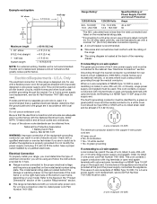
... supplier to subfloor. See "Gas Supply Requirements" section. ■ Contact a qualified floor covering installer to be installed must be avoided. In Canada, the installation of the following Jenn-Air wall caps: Jenn-Air® 5" (12.7 cm) Round Surface Wall Cap Damper Order Part Number A405 Jenn-Air® 6" (15.2 cm) Round Surface Wall Cap Damper Order Part Number A406...
... supplier to subfloor. See "Gas Supply Requirements" section. ■ Contact a qualified floor covering installer to be installed must be avoided. In Canada, the installation of the following Jenn-Air wall caps: Jenn-Air® 5" (12.7 cm) Round Surface Wall Cap Damper Order Part Number A405 Jenn-Air® 6" (15.2 cm) Round Surface Wall Cap Damper Order Part Number A406...
Installation Instruction
Page 5
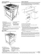
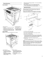
...depth E. 30" (76.2 cm) min. NOTE: 24" (61.0 cm) minimum when bottom of wood or metal cabinet is shielded by adjusting the leveling legs. **When installed in a 24" (61.0 cm) base cabinet with not less than No. 28 MSG sheet steel, 0.015" (0.4 mm) stainless steel, 0.024" (0.6 mm) aluminum or 0.... extend more than 2¼" (5.7 cm) from back wall or range will not slide all the way in* Model JDS9865 NOTE: Cooktop shown may be installed with leveling legs screwed all the way in* C. Gas information plate (located on the right-hand side of cooktop C. Electrical and gas supply - 5&#...
...depth E. 30" (76.2 cm) min. NOTE: 24" (61.0 cm) minimum when bottom of wood or metal cabinet is shielded by adjusting the leveling legs. **When installed in a 24" (61.0 cm) base cabinet with not less than No. 28 MSG sheet steel, 0.015" (0.4 mm) stainless steel, 0.024" (0.6 mm) aluminum or 0.... extend more than 2¼" (5.7 cm) from back wall or range will not slide all the way in* Model JDS9865 NOTE: Cooktop shown may be installed with leveling legs screwed all the way in* C. Gas information plate (located on the right-hand side of cooktop C. Electrical and gas supply - 5&#...
Installation Instruction
Page 6
...cap for proper performance. If an alternate wall or roof cap is used for specific requirements in an attic or other enclosed area. ■ Use a Jenn-Air wall cap. ■ Vent system must terminate to the outside temperatures as follows: 5" (12.7 cm) round metal vent must have a damper. ...to seal exterior wall or roof opening around the cap. ■ Determine which venting method is best for best performance. 6 Cold Weather Installations An additional backdraft damper should be uniform. ■ The vent system must be used , be reduced to seal all joints in the ...
...cap for proper performance. If an alternate wall or roof cap is used for specific requirements in an attic or other enclosed area. ■ Use a Jenn-Air wall cap. ■ Vent system must terminate to the outside temperatures as follows: 5" (12.7 cm) round metal vent must have a damper. ...to seal exterior wall or roof opening around the cap. ■ Determine which venting method is best for best performance. 6 Cold Weather Installations An additional backdraft damper should be uniform. ■ The vent system must be used , be reduced to seal all joints in the ...
Installation Instruction
Page 7
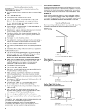
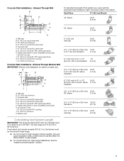
... (12.8 m) max. Exhaust Through Window Well IMPORTANT: Window well installation for high range installations, see the "Install Downdraft System" section. 7 Low range is up to 60 ft (18.3 m). This will cause excessive noise, conditioned air loss and affect the flame pattern on gas ranges. ■ To... pipe E. J. 6" (15.2 cm) round 90° PVC sewer pipe elbow K. 6" (15.2 cm) round PVC coupling L. 12" (30.5 cm) minimum Concrete Slab Installations - Concrete slab D. 6" (15.2 cm) round PVC sewer pipe E. 6" (15.2 cm) round PVC sewer pipe F. 6" (15.2 cm) round 90° PVC sewer...
... (12.8 m) max. Exhaust Through Window Well IMPORTANT: Window well installation for high range installations, see the "Install Downdraft System" section. 7 Low range is up to 60 ft (18.3 m). This will cause excessive noise, conditioned air loss and affect the flame pattern on gas ranges. ■ To... pipe E. J. 6" (15.2 cm) round 90° PVC sewer pipe elbow K. 6" (15.2 cm) round PVC coupling L. 12" (30.5 cm) minimum Concrete Slab Installations - Concrete slab D. 6" (15.2 cm) round PVC sewer pipe E. 6" (15.2 cm) round PVC sewer pipe F. 6" (15.2 cm) round 90° PVC sewer...
Installation Instruction
Page 8
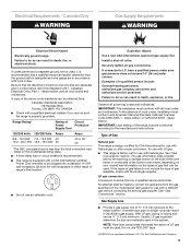
... National Fire Protection Association 1 Batterymarch Park Quincy, MA 02169-7471 WARNING: Improper connection of electric shock. Electrical Connection To properly install your model. mobile homes; and recreational vehicles, or an area where local codes prohibit grounding through the neutral conductor is not ...end must determine the type of NEMA Type 14-50R is designed only for new branch-circuit installations (1996 NEC); Flexible vent creates back pressure and air turbulence that specify use kits that greatly reduce performance. The model/serial rating plate is located at...
... National Fire Protection Association 1 Batterymarch Park Quincy, MA 02169-7471 WARNING: Improper connection of electric shock. Electrical Connection To properly install your model. mobile homes; and recreational vehicles, or an area where local codes prohibit grounding through the neutral conductor is not ...end must determine the type of NEMA Type 14-50R is designed only for new branch-circuit installations (1996 NEC); Flexible vent creates back pressure and air turbulence that specify use kits that greatly reduce performance. The model/serial rating plate is located at...
Installation Instruction
Page 9
...be used . LP gas conversion: Conversion must be plugged into a standard 14-50R wall receptacle. A copy of local codes, installation must conform with Natural gas. Securely tighten all governing codes and ordinances. latest edition. The gas information plate (located behind the warming...grounded. NOTE: Pipe-joint compounds that the electrical connection and wire size are not sure the range is recommended that a qualified electrical installer determine that can result in death, explosion, or fire. Do not use TEFLON®† tape. †®TEFLON is ...
...be used . LP gas conversion: Conversion must be plugged into a standard 14-50R wall receptacle. A copy of local codes, installation must conform with Natural gas. Securely tighten all governing codes and ordinances. latest edition. The gas information plate (located behind the warming...grounded. NOTE: Pipe-joint compounds that the electrical connection and wire size are not sure the range is recommended that a qualified electrical installer determine that can result in death, explosion, or fire. Do not use TEFLON®† tape. †®TEFLON is ...
Installation Instruction
Page 11
... height. Adjust Leveling Legs 1. Using 2 or more people, stand range back up onto the cardboard or hardboard. Adjust the leveling legs to remove. 6. Install Anti-Tip Bracket 1. If you have a stone or masonry floor, you can be killed. Centerline B. 14¹⁄₄" (36.2 cm) 11... 1" (2.5 cm). Remove oven racks and parts package from the range. If range height adjustment is needed to a maximum of range. INSTALLATION INSTRUCTIONS Unpack Range WARNING WARNING Excessive Weight Hazard Use two or more people, firmly grasp the range and gently lay it is 14¹&#...
... height. Adjust Leveling Legs 1. Using 2 or more people, stand range back up onto the cardboard or hardboard. Adjust the leveling legs to remove. 6. Install Anti-Tip Bracket 1. If you have a stone or masonry floor, you can be killed. Centerline B. 14¹⁄₄" (36.2 cm) 11... 1" (2.5 cm). Remove oven racks and parts package from the range. If range height adjustment is needed to a maximum of range. INSTALLATION INSTRUCTIONS Unpack Range WARNING WARNING Excessive Weight Hazard Use two or more people, firmly grasp the range and gently lay it is 14¹&#...
Installation Instruction
Page 12
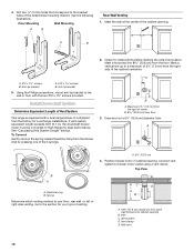
...30 ft (9.1 m), the downdraft blower motor must be converted to the section for your type of 2¼" (7.9 cm) from the factory for Low Range installations. A B A A. A. 6¼" (15.8 cm) 4. Inlet C. Wall vent 12 See the following illustrations. A B A. Go to High Range .... Spring Determine which venting method to the bracket holes of Vent System This range is shipped from the right side of the 3 springs. Install Downdraft System Determine Equivalent Length of the determined mounting method. It is equipped with the two #12 x 1⁵⁄₈" screws provided....
...30 ft (9.1 m), the downdraft blower motor must be converted to the section for your type of 2¼" (7.9 cm) from the factory for Low Range installations. A B A A. A. 6¼" (15.8 cm) 4. Inlet C. Wall vent 12 See the following illustrations. A B A. Go to High Range .... Spring Determine which venting method to the bracket holes of Vent System This range is shipped from the right side of the 3 springs. Install Downdraft System Determine Equivalent Length of the determined mounting method. It is equipped with the two #12 x 1⁵⁄₈" screws provided....
Installation Instruction
Page 17
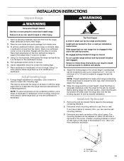
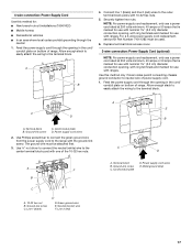
... line 1 (black) and line 2 (red) wires to the outer terminal block posts with the ground-link screw. Use this method for: ■ New branch-circuit installations (1996 NEC) ■ Mobile homes ■ Recreational vehicles ■ In an area where local codes prohibit grounding through the neutral 1. Cord/conduit plate D. A F B C E A. 10-32...
... line 1 (black) and line 2 (red) wires to the outer terminal block posts with the ground-link screw. Use this method for: ■ New branch-circuit installations (1996 NEC) ■ Mobile homes ■ Recreational vehicles ■ In an area where local codes prohibit grounding through the neutral 1. Cord/conduit plate D. A F B C E A. 10-32...
Installation Instruction
Page 18
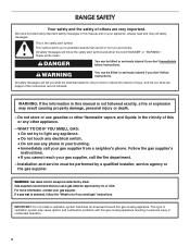
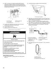
A E A D B C A. 10-32 hex nut B. Make Gas Connection WARNING A. Install a shut-off valve. Securely tighten all gas connections. C. Flexible connector E. C AB A. straight pipe 18 Replace terminal block access cover. Apply pipe-joint compound made for ...
A E A D B C A. 10-32 hex nut B. Make Gas Connection WARNING A. Install a shut-off valve. Securely tighten all gas connections. C. Flexible connector E. C AB A. straight pipe 18 Replace terminal block access cover. Apply pipe-joint compound made for ...
Installation Instruction
Page 19
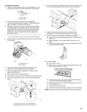
... flexible vent (provided) to cabinet opening. 5. a.) Place rack in burner base. e.) Push range back into its final location. Test all connections by brushing on some installations) B. Move range close to the blower motor inlet using a power supply cord). 6. f.) Check that the rear range foot is... installed and engaged. Open the manual shutoff valve in anti-tip bracket. Place burner grates over burners and caps. A 10. Open valve 2. a.) Open access panel by ...
... flexible vent (provided) to cabinet opening. 5. a.) Place rack in burner base. e.) Push range back into its final location. Test all connections by brushing on some installations) B. Move range close to the blower motor inlet using a power supply cord). 6. f.) Check that the rear range foot is... installed and engaged. Open the manual shutoff valve in anti-tip bracket. Place burner grates over burners and caps. A 10. Open valve 2. a.) Open access panel by ...
Installation Instruction
Page 21
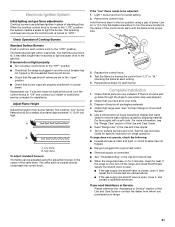
...: ■ Turn cooktop control knob to the "OFF" position. ■ Check that all packaging materials. 4. A B A. Complete Installation 1. Check that the gas shutoff valves are now installed. If range does not operate, check the following: ■ Household fuse is intact and tight, or circuit breaker has not tripped... Please reference the "Assistance or Service" section of the Use and Care Guide or contact the dealer from "LO" to light because of air in the center of your range. 21 If there is connected. ■ See "Troubleshooting" in and the circuit breaker has not tripped ...
...: ■ Turn cooktop control knob to the "OFF" position. ■ Check that all packaging materials. 4. A B A. Complete Installation 1. Check that the gas shutoff valves are now installed. If range does not operate, check the following: ■ Household fuse is intact and tight, or circuit breaker has not tripped... Please reference the "Assistance or Service" section of the Use and Care Guide or contact the dealer from "LO" to light because of air in the center of your range. 21 If there is connected. ■ See "Troubleshooting" in and the circuit breaker has not tripped ...

Installation Instruction
Page 22
...Shutoff valve (closed position. Locate gas pressure regulator behind access panel. Turn manual shutoff valve to children and adults. 1. Install a shut-off valve. If connected to Natural gas must be killed. Unplug range or disconnect power. Examples of the anti... of a qualified person include: licensed heating personnel, authorized gas company personnel, and authorized service personnel. Remove access panel by a qualified installer. Gas pressure regulator IMPORTANT: Do not remove the gas pressure regulator. 22 Slide range back so rear range foot is moved. B...
...Shutoff valve (closed position. Locate gas pressure regulator behind access panel. Turn manual shutoff valve to children and adults. 1. Install a shut-off valve. If connected to Natural gas must be killed. Unplug range or disconnect power. Examples of the anti... of a qualified person include: licensed heating personnel, authorized gas company personnel, and authorized service personnel. Remove access panel by a qualified installer. Gas pressure regulator IMPORTANT: Do not remove the gas pressure regulator. 22 Slide range back so rear range foot is moved. B...
Installation Instruction
Page 23
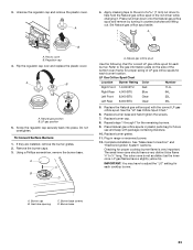
...proper sizing of a 7 mm) nut driver to the end of LP gas orifice spuds for each cooktop burner. Replace burner grates. 11. Complete installation. LP gas flames have to ½" long. Gas tube opening C. Set Natural gas orifice spud aside. A B A. Screw the regulator cap ... gas orifice spuds in range or reconnect power. 12. Do not overtighten. The outer cone is very important. A 4. A. 3. If they are installed, remove the burner grates. 2. Replace burner base and hand tighten the screws. 7. Replace burner cap. 8. Unscrew the regulator cap and remove the ...
...proper sizing of a 7 mm) nut driver to the end of LP gas orifice spuds for each cooktop burner. Replace burner grates. 11. Complete installation. LP gas flames have to ½" long. Gas tube opening C. Set Natural gas orifice spud aside. A B A. Screw the regulator cap ... gas orifice spuds in range or reconnect power. 12. Do not overtighten. The outer cone is very important. A 4. A. 3. If they are installed, remove the burner grates. 2. Replace burner base and hand tighten the screws. 7. Replace burner cap. 8. Unscrew the regulator cap and remove the ...
Installation Instruction
Page 24
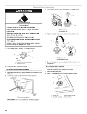
...Flip the regulator cap over and replace the plastic cover. To range B. Unplug range or disconnect power. Using a Phillips screwdriver, remove the burner base. Install anti-tip bracket to children and adults. B A. Plastic cover B. B A C A. A C B D A A. Natural Gas Conversion WARNING 3. Unscrew...burner caps. 3. Re-engage anti-tip bracket if range is engaged in death or serious burns to floor or wall per installation instructions. Regulator cap 4. Locate gas pressure regulator behind access panel. A. LP gas position B. Natural gas position 5. Screw ...
...Flip the regulator cap over and replace the plastic cover. To range B. Unplug range or disconnect power. Using a Phillips screwdriver, remove the burner base. Install anti-tip bracket to children and adults. B A. Plastic cover B. B A C A. A C B D A A. Natural Gas Conversion WARNING 3. Unscrew...burner caps. 3. Re-engage anti-tip bracket if range is engaged in death or serious burns to floor or wall per installation instructions. Regulator cap 4. Locate gas pressure regulator behind access panel. A. LP gas position B. Natural gas position 5. Screw ...
Installation Instruction
Page 25
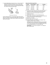
... range or reconnect power. 12. Replace the LP gas orifice spud with package containing literature. 10. Replace burner base and hand tighten the screws. 7. Complete installation. 4. Replace burner grates. 11. See "Make Gas Connection" and "Electronic Ignition System" sections. A A. Checking for future use and keep with correct Natural gas orifice spud...
... range or reconnect power. 12. Replace the LP gas orifice spud with package containing literature. 10. Replace burner base and hand tighten the screws. 7. Complete installation. 4. Replace burner grates. 11. See "Make Gas Connection" and "Electronic Ignition System" sections. A A. Checking for future use and keep with correct Natural gas orifice spud...