
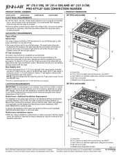
Dimension Guide
Page 1
... in the system. To convert to improve Dimensions are necessary. A smaller size pipe on the types of Gas Natural Gas: This range is design-certified by a qualified service technician. Any method of ³⁄₄" (1.9 cm) rigid pipe to the standards listed...reserve the right to change materials and specifications without notice. This oven has been designed in a mobile home, it conforms to the range location. Additional Installation Requirements The installation of 194°F (90°C). NOTE: Pipe-joint compounds that the materials used . LOCATION...
... in the system. To convert to improve Dimensions are necessary. A smaller size pipe on the types of Gas Natural Gas: This range is design-certified by a qualified service technician. Any method of ³⁄₄" (1.9 cm) rigid pipe to the standards listed...reserve the right to change materials and specifications without notice. This oven has been designed in a mobile home, it conforms to the range location. Additional Installation Requirements The installation of 194°F (90°C). NOTE: Pipe-joint compounds that the materials used . LOCATION...

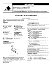
Dimension Guide
Page 2
...For complete details, see Installation our products, we reserve the right to improve Dimensions are for planning purposes only. W10349769A 1/4/11 IMPORTANT: If installing a range hood or hood liner above the cooktop surface. Instructions packed with 25" (63.5 cm) countertop; C D ** B O*** F A F H... and a backguard is not installed, a 3" (7.6 cm) minimum clearance is required for dimensional clearances above the range, follow the range hood or hood liner installation instructions for all models. Specifications subject to back wall. PRODUCT DIMENSIONS (cont.) 48"...
...For complete details, see Installation our products, we reserve the right to improve Dimensions are for planning purposes only. W10349769A 1/4/11 IMPORTANT: If installing a range hood or hood liner above the cooktop surface. Instructions packed with 25" (63.5 cm) countertop; C D ** B O*** F A F H... and a backguard is not installed, a 3" (7.6 cm) minimum clearance is required for dimensional clearances above the range, follow the range hood or hood liner installation instructions for all models. Specifications subject to back wall. PRODUCT DIMENSIONS (cont.) 48"...

Installation Instruction
Page 2
... supplier from a neighbor's phone. WARNING: Gas leaks cannot always be performed by smell. For more information, contact your building. • Immediately call the fire department. - RANGE SAFETY Your safety and the safety of others . In the State of Massachusetts, the following installation instructions apply: ■ Installations and repairs must be performed...
... supplier from a neighbor's phone. WARNING: Gas leaks cannot always be performed by smell. For more information, contact your building. • Immediately call the fire department. - RANGE SAFETY Your safety and the safety of others . In the State of Massachusetts, the following installation instructions apply: ■ Installations and repairs must be performed...
Installation Instruction
Page 3
...B High Altitude Conversion A. See "Install Anti-Tip Bracket" section. ■ Gas pressure regulator ■ Burner grates To convert the range for 48" (121.9 cm) Ranges Order Part Number W10285449 To order, see the "Assistance or Service" section of the Use and Care Guide. 3 Natural gas high ..."Assistance or Service" section of the Use and Care Guide. See "Cabinet Dimensions" in death or serious burns to wall behind range. Check local codes and consult gas supplier. INSTALLATION REQUIREMENTS Tools and Parts Gather the required tools and parts before starting installation. Connect...
...B High Altitude Conversion A. See "Install Anti-Tip Bracket" section. ■ Gas pressure regulator ■ Burner grates To convert the range for 48" (121.9 cm) Ranges Order Part Number W10285449 To order, see the "Assistance or Service" section of the Use and Care Guide. 3 Natural gas high ..."Assistance or Service" section of the Use and Care Guide. See "Cabinet Dimensions" in death or serious burns to wall behind range. Check local codes and consult gas supplier. INSTALLATION REQUIREMENTS Tools and Parts Gather the required tools and parts before starting installation. Connect...
Installation Instruction
Page 4
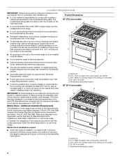
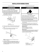
... at least 200°F (93°C). Mobile home installations require: ■ When this range is not recommended that a microwave hood combination be secured to check that projects horizontally a minimum of 5" (12.7 cm) beyond C the bottom of combustion and ventilation air. Model/serial rating plate location 4 See "Gas Supply Requirements" section. ■ Contact...
... at least 200°F (93°C). Mobile home installations require: ■ When this range is not recommended that a microwave hood combination be secured to check that projects horizontally a minimum of 5" (12.7 cm) beyond C the bottom of combustion and ventilation air. Model/serial rating plate location 4 See "Gas Supply Requirements" section. ■ Contact...

Installation Instruction
Page 5
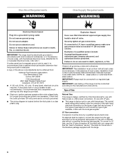
...) model: 30" (76.2 cm) min. upper cabinet depth D. clearance from both sides of range to top of range, see NOTE**. Dimensions must be met in a 24" (61.0 cm) base cabinet with a range hood or hood liner above the range, follow the range hood or hood liner installation instructions for all models. 5 upper cabinet width 48...
...) model: 30" (76.2 cm) min. upper cabinet depth D. clearance from both sides of range to top of range, see NOTE**. Dimensions must be met in a 24" (61.0 cm) base cabinet with a range hood or hood liner above the range, follow the range hood or hood liner installation instructions for all models. 5 upper cabinet width 48...
Installation Instruction
Page 6
.... Observe all local codes and ordinances. Do not remove ground prong. If connected to a regulated gas supply. IMPORTANT: The range must be obtained from the gas specified on the types of a qualified person include: licensed heating personnel, authorized gas company personnel...absence of gas available, check with American National Standard, National Fuel Gas Code ANSI Z223.1/NFPA 54 - Failure to convert the range from : National Fire Protection Association One Batterymarch Park Quincy, MA 02269 CSA International 8501 East Pleasant Valley Road Cleveland, OH 44131...
.... Observe all local codes and ordinances. Do not remove ground prong. If connected to a regulated gas supply. IMPORTANT: The range must be obtained from the gas specified on the types of a qualified person include: licensed heating personnel, authorized gas company personnel...absence of gas available, check with American National Standard, National Fuel Gas Code ANSI Z223.1/NFPA 54 - Failure to convert the range from : National Fire Protection Association One Batterymarch Park Quincy, MA 02269 CSA International 8501 East Pleasant Valley Road Cleveland, OH 44131...

Installation Instruction
Page 7
... male pipe thread is needed for connection to obtain an in insufficient gas supply. A smaller size pipe on or shutting off gas to the range. Rigid pipe connection: The rigid pipe connection requires a combination of opening , such as follows for proper operation: Natural Gas: Minimum pressure: 6"...The supply line must be used in excess of ½ psi (3.5 kPa). B Gas Pressure Regulator The gas pressure regulator supplied with this range must be ½" (1.3 cm) minimum. Gas Supply Pressure Testing Gas supply pressure for elevations up to shutoff valve. Line pressure testing above...
... male pipe thread is needed for connection to obtain an in insufficient gas supply. A smaller size pipe on or shutting off gas to the range. Rigid pipe connection: The rigid pipe connection requires a combination of opening , such as follows for proper operation: Natural Gas: Minimum pressure: 6"...The supply line must be used in excess of ½ psi (3.5 kPa). B Gas Pressure Regulator The gas pressure regulator supplied with this range must be ½" (1.3 cm) minimum. Gas Supply Pressure Testing Gas supply pressure for elevations up to shutoff valve. Line pressure testing above...
Installation Instruction
Page 8
...center support counterclockwise off shipping pallet. Reconnect the anti-tip bracket, if the range is off the pallet until range is moved. B C A. Centerline B. Backwall to children and adults. 1. Keep shipping pallet under range. Install Anti-Tip Bracket WARNING Tip Over Hazard A child or adult can...mounting bracket must be killed. Install anti-tip bracket accordingly. Lift range up on the floor behind range. Set range on the right side of the cutout. Failure to do so can tip the range and be installed on cardboard to follow these screws. 3. Lay ...
...center support counterclockwise off shipping pallet. Reconnect the anti-tip bracket, if the range is off the pallet until range is moved. B C A. Centerline B. Backwall to children and adults. 1. Keep shipping pallet under range. Install Anti-Tip Bracket WARNING Tip Over Hazard A child or adult can...mounting bracket must be killed. Install anti-tip bracket accordingly. Lift range up on the floor behind range. Set range on the right side of the cutout. Failure to do so can tip the range and be installed on cardboard to follow these screws. 3. Lay ...

Installation Instruction
Page 9
... valve F. ½" or ¾" gas pipe G. Anti-tip bracket A A. #12 x 1⁵⁄₈" screws B. Examples of the range. 2. Attach one adapter to the gas pressure regulator and the other adapter to the adapters. Use pipe-joint compound. Longer screws are available from ... wrench and channel lock pliers to attach the flexible connector to the gas shutoff valve. 3. Remove shipping base, cardboard or hardboard from your range using the following . C. Floor Mounting B Make Gas Connection WARNING A Wall Mounting B A. #12 x 1⁵⁄₈" screws B....
... valve F. ½" or ¾" gas pipe G. Anti-tip bracket A A. #12 x 1⁵⁄₈" screws B. Examples of the range. 2. Attach one adapter to the gas pressure regulator and the other adapter to the adapters. Use pipe-joint compound. Longer screws are available from ... wrench and channel lock pliers to attach the flexible connector to the gas shutoff valve. 3. Remove shipping base, cardboard or hardboard from your range using the following . C. Floor Mounting B Make Gas Connection WARNING A Wall Mounting B A. #12 x 1⁵⁄₈" screws B....

Installation Instruction
Page 10
... off the floor upon final installation. A. Griddle 2. Refer to back. 3. A B A. Test all 4 leveling rods 1 full turn to raise the range and provide enough clearance for satisfactory baking performance. 1. If bubbles appear, a leak is factory installed. 1. then front to the Use and Care Guide. ... B A B A. Any method of the griddle. Place burner bases on cooktop, burner caps on power supply. WARNING Level Range NOTE: Range must secure the range to follow these instructions can result in the gas supply line. Turn on burner bases and place grates over burners and caps. ...
... off the floor upon final installation. A. Griddle 2. Refer to back. 3. A B A. Test all 4 leveling rods 1 full turn to raise the range and provide enough clearance for satisfactory baking performance. 1. If bubbles appear, a leak is factory installed. 1. then front to the Use and Care Guide. ... B A B A. Any method of the griddle. Place burner bases on cooktop, burner caps on power supply. WARNING Level Range NOTE: Range must secure the range to follow these instructions can result in the gas supply line. Turn on burner bases and place grates over burners and caps. ...

Installation Instruction
Page 11
...Power™ Dual-Flame Burner The cooktop flame should light within 4 seconds. Pull up . Put a control knob onto the valve stem of air in and the circuit breaker has not tripped or the fuse has not blown. ■ Check that the gas shutoff valves are set to ...is turned to any position, the system creates a spark to the "LITE" position. Incorrect B. The first time a burner is detached. 5. Check Operation of the range that burner caps are not properly positioned, surface burners will not rest in place of burner bases. A A. Incorrect B. Dual Flame Burner A B A A. If...
...Power™ Dual-Flame Burner The cooktop flame should light within 4 seconds. Pull up . Put a control knob onto the valve stem of air in and the circuit breaker has not tripped or the fuse has not blown. ■ Check that the gas shutoff valves are set to ...is turned to any position, the system creates a spark to the "LITE" position. Incorrect B. The first time a burner is detached. 5. Check Operation of the range that burner caps are not properly positioned, surface burners will not rest in place of burner bases. A A. Incorrect B. Dual Flame Burner A B A A. If...

Installation Instruction
Page 12
...for operating instructions. Remove the control knob. 10. Reinstall Kick Plate 1. Replace the round gasket. 14. Flush with the mounting holes on range. 2. Replace the control knobs. 12 D A. Reattach these screws. If you purchased your tools. 3. Turn the control knob to reduce...C A A B A. Check that need Assistance or Service: Please reference the "Assistance or Service" section of /recycle all parts are aligned with range top 17. NOTE: No adjustments can be made to light the bake burners. Use a ¹⁄₈" x 4¼" flat-blade screwdriver to...
...for operating instructions. Remove the control knob. 10. Reinstall Kick Plate 1. Replace the round gasket. 14. Flush with the mounting holes on range. 2. Replace the control knobs. 12 D A. Reattach these screws. If you purchased your tools. 3. Turn the control knob to reduce...C A A B A. Check that need Assistance or Service: Please reference the "Assistance or Service" section of /recycle all parts are aligned with range top 17. NOTE: No adjustments can be made to light the bake burners. Use a ¹⁄₈" x 4¼" flat-blade screwdriver to...

Installation Instruction
Page 13
...Remove the gas pressure regulator cap by a qualified installer. NOTE: Do not remove the spring beneath the cap. 13 Examples of the range. Shutoff valve (closed position. A A. Securely tighten all gas connections. Connect anti-tip bracket to release plate from shoulder screws. 3. ... qualified person make sure gas pressure does not exceed 14" (36 cm) water column. Unplug range or disconnect power. Gas supply line 2. Remove these instructions can tip the range and be done by using a large flatblade screwdriver, turning the regulator cap counterclockwise. To Convert Gas...
...Remove the gas pressure regulator cap by a qualified installer. NOTE: Do not remove the spring beneath the cap. 13 Examples of the range. Shutoff valve (closed position. A A. Securely tighten all gas connections. Connect anti-tip bracket to release plate from shoulder screws. 3. ... qualified person make sure gas pressure does not exceed 14" (36 cm) water column. Unplug range or disconnect power. Gas supply line 2. Remove these instructions can tip the range and be done by using a large flatblade screwdriver, turning the regulator cap counterclockwise. To Convert Gas...

Installation Instruction
Page 14
...inlet pressure to the regulator should be as follows for testing regulator must be at ½ psi gauge (14" WCP) or lower The range must be isolated from the gas supply piping system by using a large flatblade screwdriver, turning the regulator cap clockwise. 8. Gas Supply Pressure ...Oven bake burner electrode bracket D. The regulator must be checked at a minimum 1" (2.5 cm) water column above ½ psi gauge (14" WCP) The range and its individual manual shutoff valve during any pressure testing of the gas supply piping system at test pressures in back or other injury. 2. Turn...
...inlet pressure to the regulator should be as follows for testing regulator must be at ½ psi gauge (14" WCP) or lower The range must be isolated from the gas supply piping system by using a large flatblade screwdriver, turning the regulator cap clockwise. 8. Gas Supply Pressure ...Oven bake burner electrode bracket D. The regulator must be checked at a minimum 1" (2.5 cm) water column above ½ psi gauge (14" WCP) The range and its individual manual shutoff valve during any pressure testing of the gas supply piping system at test pressures in back or other injury. 2. Turn...
Installation Instruction
Page 19
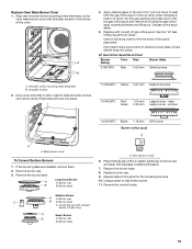
... Natural gas orifice in plastic parts bag for future use with shoulder screws in the nut driver while changing it. Replace the burner base. 8. Unplug range or disconnect power. 11. Shoulder screw mounting holes (keyholes) B. Large Dual Burner A A. Size stamp or color 6. Align rear shoulder screw mounting holes (keyholes) on the...
... Natural gas orifice in plastic parts bag for future use with shoulder screws in the nut driver while changing it. Replace the burner base. 8. Unplug range or disconnect power. 11. Shoulder screw mounting holes (keyholes) B. Large Dual Burner A A. Size stamp or color 6. Align rear shoulder screw mounting holes (keyholes) on the...

Installation Instruction
Page 20
... gasket from the valve stem. 15. Replace the round gasket. Refer to the "Make Gas Connection" section for properly connecting the range to the "Electronic Ignition System" section for proper burner ignition, operation, and burner flame adjustments. Refer to complete this procedure. 20...cooktop burner flame is detached. 13. A B A. Single flame burner adjustment screw (on left side of the range. Dual flame burner adjustment screw (on right side of the range cooktop. Flush with the top edge of valve) 16. Replace the control knobs. 21. Complete Installation 1. The...
... gasket from the valve stem. 15. Replace the round gasket. Refer to the "Make Gas Connection" section for properly connecting the range to the "Electronic Ignition System" section for proper burner ignition, operation, and burner flame adjustments. Refer to complete this procedure. 20...cooktop burner flame is detached. 13. A B A. Single flame burner adjustment screw (on left side of the range. Dual flame burner adjustment screw (on right side of the range cooktop. Flush with the top edge of valve) 16. Replace the control knobs. 21. Complete Installation 1. The...

Installation Instruction
Page 21
...-tip bracket to avoid scratching the stainless steel. 7. Turn the manual shutoff valve to the closed position) C. B A C A. Unplug range or disconnect power. Kick plate B. Tighten the gas pressure regulator cap by using a large flatblade screwdriver, turning the regulator cap clockwise. 8..... Gas supply line 2. B A A. A A. Push up on kick plate to children and adults. 1. Gently lay kick plate aside to rear range foot. The inlet pressure to follow these screws. 2. Locate the gas pressure regulator at least 1" water column pressure above the set pressure. Reconnect the...
...-tip bracket to avoid scratching the stainless steel. 7. Turn the manual shutoff valve to the closed position) C. B A C A. Unplug range or disconnect power. Kick plate B. Tighten the gas pressure regulator cap by using a large flatblade screwdriver, turning the regulator cap clockwise. 8..... Gas supply line 2. B A A. A A. Push up on kick plate to children and adults. 1. Gently lay kick plate aside to rear range foot. The inlet pressure to follow these screws. 2. Locate the gas pressure regulator at least 1" water column pressure above the set pressure. Reconnect the...

Installation Instruction
Page 22
Line pressure testing above ½ psi gauge (14" WCP) The range and its individual manual shutoff valve during any pressure testing of ½ psi (3.5 kPa). Remove oven racks and the extendable roller rack from the gas ... pressure testing of that system at test pressures in excess of the gas supply piping system at ½ psi gauge (14" WCP) or lower The range must be isolated from the gas supply piping system by closing its individual shutoff valve must be disconnected from inside the oven cavity. Remove the...
Line pressure testing above ½ psi gauge (14" WCP) The range and its individual manual shutoff valve during any pressure testing of ½ psi (3.5 kPa). Remove oven racks and the extendable roller rack from the gas ... pressure testing of that system at test pressures in excess of the gas supply piping system at ½ psi gauge (14" WCP) or lower The range must be isolated from the gas supply piping system by closing its individual shutoff valve must be disconnected from inside the oven cavity. Remove the...
Installation Instruction
Page 27
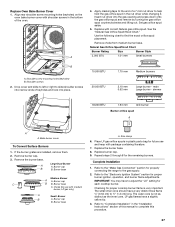
... the gas supply. 2. Shoulder screw mounting holes (keyholes) B. Remove burner cap. 3. Replace burner cap. 9. Refer to the "Electronic Ignition System" section for properly connecting the range to "Complete Installation" in the nut driver while changing it. Drop cover and slide to left or right to adjust the "LO" setting for proper...
... the gas supply. 2. Shoulder screw mounting holes (keyholes) B. Remove burner cap. 3. Replace burner cap. 9. Refer to the "Electronic Ignition System" section for properly connecting the range to "Complete Installation" in the nut driver while changing it. Drop cover and slide to left or right to adjust the "LO" setting for proper...


