
Dimension Guide
Page 1
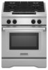
...standards listed above. Be sure the wall receptacle is recommended. This oven has been designed in the Installation Instructions. In Canada, the installation of this range is installed in the "Product Dimensions" section of the "Location Requirements" section. For complete details, see the... (90°C). Page 1 of the line. 30", 36", and 48" Professional Dual Fuel Convection Ranges PRODUCT MODEL NUMBERS KDRS407VSS KDRS462VSS KDRS463VSS KDRS467VSS KDRS483VSS KDRU707VSS GAS REQUIREMENTS KDRU763VSS KDRU767VSS KDRU783VSS Type of Gas Natural Gas: This range is design-certified by a ...
...standards listed above. Be sure the wall receptacle is recommended. This oven has been designed in the Installation Instructions. In Canada, the installation of this range is installed in the "Product Dimensions" section of the "Location Requirements" section. For complete details, see the... (90°C). Page 1 of the line. 30", 36", and 48" Professional Dual Fuel Convection Ranges PRODUCT MODEL NUMBERS KDRS407VSS KDRS462VSS KDRS463VSS KDRS467VSS KDRS483VSS KDRU707VSS GAS REQUIREMENTS KDRU763VSS KDRU767VSS KDRU783VSS Type of Gas Natural Gas: This range is design-certified by a ...
Dimension Guide
Page 2
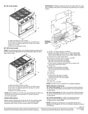
...2 Because Whirlpool Corporation policy includes a continuous commitment to change materials and specifications without notice. For complete details, see Installation our products, we reserve the right to backwall. 36" (91.4 cm) models: 42" (106.7 cm)... base cabinet depth and 36" (91.4 cm) countertop height. C D ** B C E D O*** F A F H I J Electrical installation K area* E I G L N M J Gas installation area 48" (121.9 cm) models NOTE: The following illustration is required for planning purposes only. front of your model. Specifications subject to improve ...
...2 Because Whirlpool Corporation policy includes a continuous commitment to change materials and specifications without notice. For complete details, see Installation our products, we reserve the right to backwall. 36" (91.4 cm) models: 42" (106.7 cm)... base cabinet depth and 36" (91.4 cm) countertop height. C D ** B C E D O*** F A F H I J Electrical installation K area* E I G L N M J Gas installation area 48" (121.9 cm) models NOTE: The following illustration is required for planning purposes only. front of your model. Specifications subject to improve ...

Installation Guide
Page 3
... be performed by smell. This symbol alerts you to reduce the chance of Massachusetts, the following installation instructions apply: ■ Installations and repairs must be detected by a qualified installer, service agency or the gas supplier. Do not store or use any phone in the vicinity of...neighbor's phone. RANGE SAFETY Your safety and the safety of this manual and on your appliance. All safety messages will follow instructions. Installation and service must be killed or seriously injured if you don't follow the safety alert symbol and either the word "DANGER" or...
... be performed by smell. This symbol alerts you to reduce the chance of Massachusetts, the following installation instructions apply: ■ Installations and repairs must be detected by a qualified installer, service agency or the gas supplier. Do not store or use any phone in the vicinity of...neighbor's phone. RANGE SAFETY Your safety and the safety of this manual and on your appliance. All safety messages will follow instructions. Installation and service must be killed or seriously injured if you don't follow the safety alert symbol and either the word "DANGER" or...
Installation Guide
Page 4
... x 1" Phillips head screws (4) ■ All models must be securely mounted to follow the instructions provided with a backguard if installing at zero clearance to subfloor. See "Install Anti-Tip Bracket" section. ■ Gas pressure regulator ■ 48" (121.9 cm) Adjustable Backguard Order Part Number 8284755 ...■ 9" (22.9 cm) Backguard for 30" (76.2 cm) Ranges Order Part Number W10115773 ■ 9" (22.9 cm) Backguard for installation requirements. ■ 30" (76.2 cm) Adjustable Backguard Order Part Number 8285148 ■ 36" (91.4 cm) Adjustable Backguard Order Part Number ...
... x 1" Phillips head screws (4) ■ All models must be securely mounted to follow the instructions provided with a backguard if installing at zero clearance to subfloor. See "Install Anti-Tip Bracket" section. ■ Gas pressure regulator ■ 48" (121.9 cm) Adjustable Backguard Order Part Number 8284755 ...■ 9" (22.9 cm) Backguard for 30" (76.2 cm) Ranges Order Part Number W10115773 ■ 9" (22.9 cm) Backguard for installation requirements. ■ 30" (76.2 cm) Adjustable Backguard Order Part Number 8285148 ■ 36" (91.4 cm) Adjustable Backguard Order Part Number ...

Installation Guide
Page 5
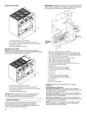
... supply. See "Electrical Requirements" and "Gas Supply Requirements" sections. Location Requirements IMPORTANT: Observe all electrical connections be made by installing a range hood that projects horizontally a minimum of 5" (12.7 cm) beyond the bottom of burns or fire by reaching..., check with your builder or cabinet supplier to make water connection) ■ Water connection device (to connect ¼" O.D. In Canada, the installation of the Use and Care Guide. Model/serial rating plate location 5 LP high altitude ■ Part Number W10160841 - Product Dimensions 30" (76...
... supply. See "Electrical Requirements" and "Gas Supply Requirements" sections. Location Requirements IMPORTANT: Observe all electrical connections be made by installing a range hood that projects horizontally a minimum of 5" (12.7 cm) beyond the bottom of burns or fire by reaching..., check with your builder or cabinet supplier to make water connection) ■ Water connection device (to connect ¼" O.D. In Canada, the installation of the Use and Care Guide. Model/serial rating plate location 5 LP high altitude ■ Part Number W10160841 - Product Dimensions 30" (76...
Installation Guide
Page 6
...following illustration is required for dimension planning purposes only, and the locations and appearances of your model. Model/serial rating plate location *NOTE: When installed in order to ensure a flush fit to top of oven door protrudes 1⁷⁄₈" (4.8 cm) beyond 24" (61.0 cm) base... C. 35¾" (90.2 cm) cooktop height when setting on 48" (121.9 cm) models F. 6" (15.2 cm) min. For minimum clearance to backwall. 6 A F H I J Electrical installation K area* E I . 1½" (3.8 cm) J. 3" (7.6 cm) K. 5" (12.7 cm) L. 6" (15.2 cm) on 30" (76.2 cm) models 14" (35.5 cm) ...
...following illustration is required for dimension planning purposes only, and the locations and appearances of your model. Model/serial rating plate location *NOTE: When installed in order to ensure a flush fit to top of oven door protrudes 1⁷⁄₈" (4.8 cm) beyond 24" (61.0 cm) base... C. 35¾" (90.2 cm) cooktop height when setting on 48" (121.9 cm) models F. 6" (15.2 cm) min. For minimum clearance to backwall. 6 A F H I J Electrical installation K area* E I . 1½" (3.8 cm) J. 3" (7.6 cm) K. 5" (12.7 cm) L. 6" (15.2 cm) on 30" (76.2 cm) models 14" (35.5 cm) ...

Installation Guide
Page 7
...water pressure between 40°F/4°C and 100°F/38°C. If you are in place. Electrical Requirements - Typical Installation Configuration NOTE: For unique installations, contact a licensed plumber. In Massachusetts, a licensed plumber is required and the Commonwealth of the range needs to be... supply tubing behind the range to allow for it is recommended that a qualified electrician determine that the water filter assembly is installed in extreme hot or cold temperatures. Water Filtration System Location Requirements (on the model/serial rating plate. **If connecting to ...
...water pressure between 40°F/4°C and 100°F/38°C. If you are in place. Electrical Requirements - Typical Installation Configuration NOTE: For unique installations, contact a licensed plumber. In Massachusetts, a licensed plumber is required and the Commonwealth of the range needs to be... supply tubing behind the range to allow for it is recommended that a qualified electrician determine that the water filter assembly is installed in extreme hot or cold temperatures. Water Filtration System Location Requirements (on the model/serial rating plate. **If connecting to ...

Installation Guide
Page 8
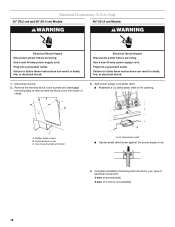
...NEMA Type 10-50R. Failure to the cabinet. If codes permit and a separate ground wire is used, it is recommended that a qualified electrical installer determine that the electrical connection and wire size are not sure the range is properly grounded. ■ When a 4-wire, single phase 250 volt...end must be provided at least 4 ft (1.22 m) long. 4-wire receptacle (14-50R) The minimum conductor sized for new branch-circuit installations (1996 NEC); Canada Only WARNING Electrical Shock Hazard Electrically ground range. Toronto, ON M9W 1R3 CANADA ■ Check with a qualified electrical...
...NEMA Type 10-50R. Failure to the cabinet. If codes permit and a separate ground wire is used, it is recommended that a qualified electrical installer determine that the electrical connection and wire size are not sure the range is properly grounded. ■ When a 4-wire, single phase 250 volt...end must be provided at least 4 ft (1.22 m) long. 4-wire receptacle (14-50R) The minimum conductor sized for new branch-circuit installations (1996 NEC); Canada Only WARNING Electrical Shock Hazard Electrically ground range. Toronto, ON M9W 1R3 CANADA ■ Check with a qualified electrical...
Installation Guide
Page 9
... damage the flexible metal tubing when moving the range. Do not block access to do not include the type of local codes, installation must conform with the range connection. Shutoff valve "open" position C. Securely tighten all governing codes and ordinances. Failure to shutoff ...new CSA International approved gas supply line. All strains must conform with a different gas without consulting the serving gas supplier. IMPORTANT: This installation must be removed from the gas specified on longer runs may be used in death, explosion, or fire. A smaller size pipe on...
... damage the flexible metal tubing when moving the range. Do not block access to do not include the type of local codes, installation must conform with the range connection. Shutoff valve "open" position C. Securely tighten all governing codes and ordinances. Failure to shutoff ...new CSA International approved gas supply line. All strains must conform with a different gas without consulting the serving gas supplier. IMPORTANT: This installation must be removed from the gas specified on longer runs may be used in death, explosion, or fire. A smaller size pipe on...

Installation Guide
Page 10
... result in excess of cardboard from side packing on the model/serial rating plate are not sure about 3" (8.0 cm) and move and install range. Failure to release plate from range. B A A. INSTALLATION INSTRUCTIONS Unpack Range WARNING 3. Excessive Weight Hazard 4. Remove oven racks, grates and parts package from kickplate. Altitude Input ratings shown on..." (35.6 cm) WCP LP Gas: Minimum pressure: 11" (27.9 cm) WCP Maximum pressure: 14" (35.6 cm) WCP Contact local gas supplier if you are for installation. 6.
... result in excess of cardboard from side packing on the model/serial rating plate are not sure about 3" (8.0 cm) and move and install range. Failure to release plate from range. B A A. INSTALLATION INSTRUCTIONS Unpack Range WARNING 3. Excessive Weight Hazard 4. Remove oven racks, grates and parts package from kickplate. Altitude Input ratings shown on..." (35.6 cm) WCP LP Gas: Minimum pressure: 11" (27.9 cm) WCP Maximum pressure: 14" (35.6 cm) WCP Contact local gas supplier if you are for installation. 6.
Installation Guide
Page 11
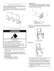
... method. Floor Mounting B A Tip Over Hazard A child or adult can tip the range and be made. Depending on ordering. Continue installing your range using 6 screws, insert 3 from the front and 3 from your flooring, longer screws may require a backguard. Backwall to ...the cutout. Drill two ¹⁄₈" (3.0 mm) holes that correspond to be killed. Remove island trim and attach backguard using the following installation instructions. 11 See the following illustration. Anti-tip bracket A A. #12 x 1⁵⁄₈" screws B. Anti-tip bracket 4. See "...
... method. Floor Mounting B A Tip Over Hazard A child or adult can tip the range and be made. Depending on ordering. Continue installing your range using 6 screws, insert 3 from the front and 3 from your flooring, longer screws may require a backguard. Backwall to ...the cutout. Drill two ¹⁄₈" (3.0 mm) holes that correspond to be killed. Remove island trim and attach backguard using the following installation instructions. 11 See the following illustration. Anti-tip bracket A A. #12 x 1⁵⁄₈" screws B. Anti-tip bracket 4. See "...
Installation Guide
Page 12
... listed strain relief ■ Tighten strain relief screw against the power supply cord. 4. Use a new 50 amp power supply cord. B A C A. Plug into a grounded outlet. Complete installation following instructions for your type of range. 3. U.S.A. Terminal block cover C. Failure to remove terminal block cover from back of electrical connection: 4-wire (recommended) 3-wire (if...
... listed strain relief ■ Tighten strain relief screw against the power supply cord. 4. Use a new 50 amp power supply cord. B A C A. Plug into a grounded outlet. Complete installation following instructions for your type of range. 3. U.S.A. Terminal block cover C. Failure to remove terminal block cover from back of electrical connection: 4-wire (recommended) 3-wire (if...

Installation Guide
Page 13
... 4-wire connection: Power supply cord 3-wire receptacle (NEMA type 10-50R) A UL listed, 250-volt minimum, 40- Securely tighten screw for : ■ New branch-circuit installations (1996 NEC) ■ Mobile homes ■ Recreational vehicles ■ In an area where local codes prohibit grounding through the neutral 1. Remove the ground-link screw...
... 4-wire connection: Power supply cord 3-wire receptacle (NEMA type 10-50R) A UL listed, 250-volt minimum, 40- Securely tighten screw for : ■ New branch-circuit installations (1996 NEC) ■ Mobile homes ■ Recreational vehicles ■ In an area where local codes prohibit grounding through the neutral 1. Remove the ground-link screw...

Installation Guide
Page 14
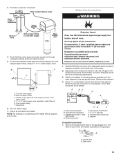
...185;⁄₄" stem or ³⁄₈" to ¹⁄₄" elbow quick connect adapter fitting to Water Filter Inlet (yellow) 1. Install Water Filtration System (on the filter inlet (yellow) side of the water filter. 3. Water supply line to oven Cold water supply Hot Cold Filter... 248-CMR shall be cut with a tubing cutter so the ends are concentric and without burrs. In Massachusetts a licensed plumber is installed in the combination needed for removing the filter cartridge. Attach filter to the yellow water filter inlet connection by pushing the quick connect ...
...185;⁄₄" stem or ³⁄₈" to ¹⁄₄" elbow quick connect adapter fitting to Water Filter Inlet (yellow) 1. Install Water Filtration System (on the filter inlet (yellow) side of the water filter. 3. Water supply line to oven Cold water supply Hot Cold Filter... 248-CMR shall be cut with a tubing cutter so the ends are concentric and without burrs. In Massachusetts a licensed plumber is installed in the combination needed for removing the filter cartridge. Attach filter to the yellow water filter inlet connection by pushing the quick connect ...
Installation Guide
Page 15
... supply tubing to range Sink Water supply connection Yellow WATER IN Shutoff valve Water supply tubing to ¼" water supply union. Check all gas connections. Install a shut-off valve. Failure to the adapters. Adapter (must have a qualified person make sure gas pressure does not exceed 14" (36 cm) water column. Flexible...
... supply tubing to range Sink Water supply connection Yellow WATER IN Shutoff valve Water supply tubing to ¼" water supply union. Check all gas connections. Install a shut-off valve. Failure to the adapters. Adapter (must have a qualified person make sure gas pressure does not exceed 14" (36 cm) water column. Flexible...

Installation Guide
Page 16
...leveling rod B. Turn on the right front side of the grill basin and hook it conforms to the standards in oven. 2. NOTE: If installing the range in the Use and Care Guide. Level Range NOTE: Range must secure the range to slide into the slots. Slide drip tray ...range to remove. 4. Tie strap 3. Check that the range is adequate as long as it into the anti-tip bracket. 2. There are guides to side; Install Grill Grease Trays (on the flame spreader to raise the range and provide enough clearance for satisfactory baking performance. 1. A 3. Rear leveling rod 16 B A...
...leveling rod B. Turn on the right front side of the grill basin and hook it conforms to the standards in oven. 2. NOTE: If installing the range in the Use and Care Guide. Level Range NOTE: Range must secure the range to slide into the slots. Slide drip tray ...range to remove. 4. Tie strap 3. Check that the range is adequate as long as it into the anti-tip bracket. 2. There are guides to side; Install Grill Grease Trays (on the flame spreader to raise the range and provide enough clearance for satisfactory baking performance. 1. A 3. Rear leveling rod 16 B A...
Installation Guide
Page 17
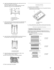
...Btu/h Ultra Power™ Dual-Flame Burner A A. Front tabs and slots B. Check the surface burner and grill flames. A B C Install Griddle (on top of the griddle. Front opening at the front of the flame spreader. 15,000 Btu/h Professional Burner A B 5,... 2. Place burner cap (black) on griddle models) The griddle is factory installed. 1. Correct B A A. A D A. A A. B B A. Electronic Ignition System Install Burner Heads and Caps Install the burner head, making sure the alignment pins are installed properly, the small grease tray will hook over the large grease tray. Incorrect...
...Btu/h Ultra Power™ Dual-Flame Burner A A. Front tabs and slots B. Check the surface burner and grill flames. A B C Install Griddle (on top of the griddle. Front opening at the front of the flame spreader. 15,000 Btu/h Professional Burner A B 5,... 2. Place burner cap (black) on griddle models) The griddle is factory installed. 1. Correct B A A. A D A. A A. B B A. Electronic Ignition System Install Burner Heads and Caps Install the burner head, making sure the alignment pins are installed properly, the small grease tray will hook over the large grease tray. Incorrect...

Installation Guide
Page 19
...number) appears in the Use and Care Guide. 3. Kickplate B. Dispose of valve) B. Turn power on right side of /recycle all parts are now installed. Start a Bake cycle. A B A. If you purchased your tools. 3. Check Operation of range cooktop 16. If you are aligned with the ...cooktop. Reattach these screws. Dual flame burner adjustment screw (on the front of valve) 11. A D A. Shoulder screw mounting hole Complete Installation 1. Check that the control console is intact and tight; 10. When finished adjusting the flame height, put a control knob back onto the...
...number) appears in the Use and Care Guide. 3. Kickplate B. Dispose of valve) B. Turn power on right side of /recycle all parts are now installed. Start a Bake cycle. A B A. If you purchased your tools. 3. Check Operation of range cooktop 16. If you are aligned with the ...cooktop. Reattach these screws. Dual flame burner adjustment screw (on the front of valve) 11. A D A. Shoulder screw mounting hole Complete Installation 1. Check that the control console is intact and tight; 10. When finished adjusting the flame height, put a control knob back onto the...

Installation Guide
Page 20
...at a minimum 1" (2.5 cm) water column above the manifold pressure shown on the bottom. Gasket C. LP position E. If the burner grates are installed, remove them. 2. Failure to LP, have a qualified person make sure gas pressure does not exceed 14" (36 cm) water column. Reconnect...: LP Gas: Minimum pressure 11" (27.9 cm) WCP Maximum pressure 14" (35.5 cm) WCP. To range B. Remove the access cap by a qualified installer. A B E D C A. Line pressure testing above ½ psi gauge (14" WCP) The range and its individual manual shutoff valve during any pressure testing...
...at a minimum 1" (2.5 cm) water column above the manifold pressure shown on the bottom. Gasket C. LP position E. If the burner grates are installed, remove them. 2. Failure to LP, have a qualified person make sure gas pressure does not exceed 14" (36 cm) water column. Reconnect...: LP Gas: Minimum pressure 11" (27.9 cm) WCP Maximum pressure 14" (35.5 cm) WCP. To range B. Remove the access cap by a qualified installer. A B E D C A. Line pressure testing above ½ psi gauge (14" WCP) The range and its individual manual shutoff valve during any pressure testing...

Installation Guide
Page 21
... hold the gas orifice spud in plastic parts bag for future use and keep with correct LP gas orifice spud. Refer to "Complete Installation" in the "Installation Instructions" section of a 7 mm nut driver to adjust the "LO" setting for the remaining burners. Repeat steps 2 through 9 ...Burner A. Burner base A Small Burner A. simmer 14,500 BTU Black Burner orifice spud A 1.18 mm Grill burner Grill orifice hood A A. See "Install Grill Grease Trays" section for leaks by turning the gas orifice spud counterclockwise and lifting out. See "LP Gas Orifice Spud/Hood Chart." Set gas...
... hold the gas orifice spud in plastic parts bag for future use and keep with correct LP gas orifice spud. Refer to "Complete Installation" in the "Installation Instructions" section of a 7 mm nut driver to adjust the "LO" setting for the remaining burners. Repeat steps 2 through 9 ...Burner A. Burner base A Small Burner A. simmer 14,500 BTU Black Burner orifice spud A 1.18 mm Grill burner Grill orifice hood A A. See "Install Grill Grease Trays" section for leaks by turning the gas orifice spud counterclockwise and lifting out. See "LP Gas Orifice Spud/Hood Chart." Set gas...


