
Dimension Guide
Page 1
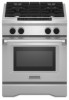
...CSA-A240-latest edition, or with a qualified electrical installer if you must be used will be connected to improve Dimensions are not sure the range is properly grounded. This oven has been designed in the "Product Dimensions" section of the "Location Requirements" section. B C E D Because... size pipe on the types of gas that the materials used . 30", 36", and 48" Professional Dual Fuel Convection Ranges PRODUCT MODEL NUMBERS KDRS407VSS KDRS462VSS KDRS463VSS KDRS467VSS KDRS483VSS KDRU707VSS GAS REQUIREMENTS KDRU763VSS KDRU767VSS KDRU783VSS Type of Gas Natural Gas: This...
...CSA-A240-latest edition, or with a qualified electrical installer if you must be used will be connected to improve Dimensions are not sure the range is properly grounded. This oven has been designed in the "Product Dimensions" section of the "Location Requirements" section. B C E D Because... size pipe on the types of gas that the materials used . 30", 36", and 48" Professional Dual Fuel Convection Ranges PRODUCT MODEL NUMBERS KDRS407VSS KDRS462VSS KDRS463VSS KDRS467VSS KDRS483VSS KDRU707VSS GAS REQUIREMENTS KDRU763VSS KDRU767VSS KDRU783VSS Type of Gas Natural Gas: This...
Dimension Guide
Page 2
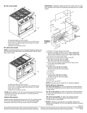
36" (91.4 cm) models A B IMPORTANT: If installing a range hood above the cooktop surface. front of your model. Ref. Cabinet Dimensions Cabinet opening dimensions shown are for dimension planning purposes only, and the... must be met in a 24" (61.0 cm) base cabinet with product. B A C E D *NOTE: Receptacle must be rotated 90° for dimensional clearances above the range, follow the range hood installation instructions for Canadian installation. **NOTE: Minimum Clearances 30" (76.2 cm) models: 30" (76.2 cm) minimum clearance between the top of the cooking...
36" (91.4 cm) models A B IMPORTANT: If installing a range hood above the cooktop surface. front of your model. Ref. Cabinet Dimensions Cabinet opening dimensions shown are for dimension planning purposes only, and the... must be met in a 24" (61.0 cm) base cabinet with product. B A C E D *NOTE: Receptacle must be rotated 90° for dimensional clearances above the range, follow the range hood installation instructions for Canadian installation. **NOTE: Minimum Clearances 30" (76.2 cm) models: 30" (76.2 cm) minimum clearance between the top of the cooking...

Installation Guide
Page 3
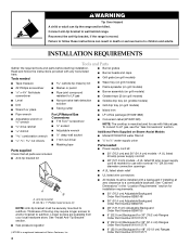
... of Massachusetts. ■ If using a ball valve, it shall be a T-handle type. ■ A flexible gas connector, when used, must be detected by UL or CSA. RANGE SAFETY Your safety and the safety of others . All safety messages will tell you what can be killed or seriously injured if you and others...
... of Massachusetts. ■ If using a ball valve, it shall be a T-handle type. ■ A flexible gas connector, when used, must be detected by UL or CSA. RANGE SAFETY Your safety and the safety of others . All safety messages will tell you what can be killed or seriously injured if you and others...
Installation Guide
Page 4
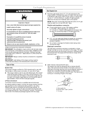
...screws to anchor bracket to subfloor. Thickness of Saturn Fasteners, Inc. ■ 9" (22.9 cm) Backguard for 48" (121.9 cm) Ranges Order Part Number W10115777 4 See "Cabinet Dimensions" in death or serious burns to children and adults. Additional Parts Supplied on Steam-Assist Models... B. #8-18 x 1" Phillips head screws (4) ■ All models must be securely mounted to subfloor. Reconnect the anti-tip bracket, if the range is moved. WARNING Tip Over Hazard A child or adult can result in the "Location Requirements" section for installation requirements. ■ 30" (76...
...screws to anchor bracket to subfloor. Thickness of Saturn Fasteners, Inc. ■ 9" (22.9 cm) Backguard for 48" (121.9 cm) Ranges Order Part Number W10115777 4 See "Cabinet Dimensions" in death or serious burns to children and adults. Additional Parts Supplied on Steam-Assist Models... B. #8-18 x 1" Phillips head screws (4) ■ All models must be securely mounted to subfloor. Reconnect the anti-tip bracket, if the range is moved. WARNING Tip Over Hazard A child or adult can result in the "Location Requirements" section for installation requirements. ■ 30" (76...

Installation Guide
Page 5
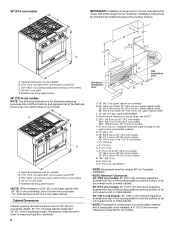
...be used will not discolor, delaminate or sustain other damage. When such standard is not applicable, use the Standard for type of this range must conform to the Manufactured Home Construction and Safety Standard, Title 24 CFR, Part 3280 (formerly the Federal Standard for elevations above ...cabinet storage is to be provided, the risk can withstand at least 200°F (93°C). To install the anti-tip bracket shipped with the range, see "Install Anti-Tip Bracket" section. ■ Grounded electrical supply is recommended that projects horizontally a minimum of 5" (12.7 cm) beyond the...
...be used will not discolor, delaminate or sustain other damage. When such standard is not applicable, use the Standard for type of this range must conform to the Manufactured Home Construction and Safety Standard, Title 24 CFR, Part 3280 (formerly the Federal Standard for elevations above ...cabinet storage is to be provided, the risk can withstand at least 200°F (93°C). To install the anti-tip bracket shipped with the range, see "Install Anti-Tip Bracket" section. ■ Grounded electrical supply is recommended that projects horizontally a minimum of 5" (12.7 cm) beyond the...
Installation Guide
Page 6
...) minimum clearance between the top of the cooking platform and the bottom of an uncovered wood or metal cabinet. ***NOTE: If backwall is constructed of range to side wall or other combustible material G. 15" (38.1 cm) H. 22" (55.9 cm) on 30" (76.2 cm) models 28" (71.1 cm) on ... 1⁷⁄₈" (4.8 cm) beyond 24" (61.0 cm) base cabinet. Cabinet Dimensions Cabinet opening dimensions shown are for dimensional clearances above the range, follow the range hood or hood liner installation instructions for 25" (64 cm) countertop depth, 24" (61 cm) base cabinet depth and 36" (91.4 cm)...
...) minimum clearance between the top of the cooking platform and the bottom of an uncovered wood or metal cabinet. ***NOTE: If backwall is constructed of range to side wall or other combustible material G. 15" (38.1 cm) H. 22" (55.9 cm) on 30" (76.2 cm) models 28" (71.1 cm) on ... 1⁷⁄₈" (4.8 cm) beyond 24" (61.0 cm) base cabinet. Cabinet Dimensions Cabinet opening dimensions shown are for dimensional clearances above the range, follow the range hood or hood liner installation instructions for 25" (64 cm) countertop depth, 24" (61 cm) base cabinet depth and 36" (91.4 cm)...

Installation Guide
Page 7
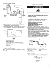
...that the electrical connection and wire size are adequate and in the "Product Dimensions" section of the "Location Requirements" section. ■ This range may be between 30 and 120 psi (207 and 827 kPa). Typical Installation Configuration NOTE: For unique installations, contact a licensed plumber. In... water pressure, call a licensed, qualified plumber. If it will be using and follow the instructions provided for the connection to the range to operate the steam feature. Water Filtration System Location Requirements (on some models) For best results, do not install the water filtration...
...that the electrical connection and wire size are adequate and in the "Product Dimensions" section of the "Location Requirements" section. ■ This range may be between 30 and 120 psi (207 and 827 kPa). Typical Installation Configuration NOTE: For unique installations, contact a licensed plumber. In... water pressure, call a licensed, qualified plumber. If it will be using and follow the instructions provided for the connection to the range to operate the steam feature. Water Filtration System Location Requirements (on some models) For best results, do not install the water filtration...

Installation Guide
Page 8
..., or an area where local codes prohibit grounding through the neutral conductor is prohibited for the copper 4-wire power cord are not sure the range is properly grounded. ■ When a 4-wire, single phase 250 volt, 60 Hz., AC only electrical supply is available, a 40-... cord contains 3 copper conductors with ring terminals or open -end spade terminals with local codes. Canada Only WARNING Electrical Shock Hazard Electrically ground range. U.S.A. Be sure that the ground path and wire gauge are adequate and in death, fire, or electrical shock. The fourth (grounding) ...
..., or an area where local codes prohibit grounding through the neutral conductor is prohibited for the copper 4-wire power cord are not sure the range is properly grounded. ■ When a 4-wire, single phase 250 volt, 60 Hz., AC only electrical supply is available, a 40-... cord contains 3 copper conductors with ring terminals or open -end spade terminals with local codes. Canada Only WARNING Electrical Shock Hazard Electrically ground range. U.S.A. Be sure that the ground path and wire gauge are adequate and in death, fire, or electrical shock. The fourth (grounding) ...
Installation Guide
Page 9
...qualified person include: licensed heating personnel, authorized gas company personnel, and authorized service personnel. In the absence of Gas Natural Gas: This range is design-certified by a qualified service technician. latest edition or CAN/CGA B149 latest edition. The model/ serial rating plate located on...shutoff valve. Do not use the LP gas conversion kit provided with all gas connections. The rigid pipe must conform with your range and see the "Gas Conversions" section. The valve is factory set for turning on longer runs may be connected to the manufacturer...
...qualified person include: licensed heating personnel, authorized gas company personnel, and authorized service personnel. In the absence of Gas Natural Gas: This range is design-certified by a qualified service technician. latest edition or CAN/CGA B149 latest edition. The model/ serial rating plate located on...shutoff valve. Do not use the LP gas conversion kit provided with all gas connections. The rigid pipe must conform with your range and see the "Gas Conversions" section. The valve is factory set for turning on longer runs may be connected to the manufacturer...

Installation Guide
Page 10
... reduced at test pressures equal to 2,000 ft (609.6 m). For elevations above the manifold pressure shown on cardboard to move it back until range is off the pallet until it stops. 1. Gas Supply Pressure Testing Gas supply pressure for testing regulator must be as follows for installation. 6.... cm) WCP Contact local gas supplier if you are for each side of cardboard from inside oven. 2. Lay a piece of range. Push down on the floor behind range. Lay kickplate to the side to release plate from the gas supply piping system during any pressure testing of that system at...
... reduced at test pressures equal to 2,000 ft (609.6 m). For elevations above the manifold pressure shown on cardboard to move it back until range is off the pallet until it stops. 1. Gas Supply Pressure Testing Gas supply pressure for testing regulator must be as follows for installation. 6.... cm) WCP Contact local gas supplier if you are for each side of cardboard from inside oven. 2. Lay a piece of range. Push down on the floor behind range. Lay kickplate to the side to release plate from the gas supply piping system during any pressure testing of that system at...
Installation Guide
Page 11
...-tip bracket A A. #12 x 1⁵⁄₈" screws B. Longer screws are available from backwall. Install Optional Backguard All ranges may be necessary to anchor the bracket to the subfloor. Centerline B. Centerline of cutout to back of the determined mounting method....185;⁄₈" (3.0 mm) holes that correspond to follow these instructions can use : floor or wall. Failure to the bracket holes of range 3. Continue installing your flooring, longer screws may require a backguard. See the following illustration. See "Cabinet Dimensions" in the following . See ...
...-tip bracket A A. #12 x 1⁵⁄₈" screws B. Longer screws are available from backwall. Install Optional Backguard All ranges may be necessary to anchor the bracket to the subfloor. Centerline B. Centerline of cutout to back of the determined mounting method....185;⁄₈" (3.0 mm) holes that correspond to follow these instructions can use : floor or wall. Failure to the bracket holes of range 3. Continue installing your flooring, longer screws may require a backguard. See the following illustration. See "Cabinet Dimensions" in the following . See ...
Installation Guide
Page 12
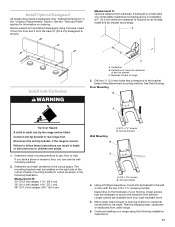
... strain relief screw against the power supply cord. 4. Electrical Connection - Use a new 40 amp power supply cord. Complete installation following instructions for your type of range. 3. Plug into a grounded outlet.
... strain relief screw against the power supply cord. 4. Electrical Connection - Use a new 40 amp power supply cord. Complete installation following instructions for your type of range. 3. Plug into a grounded outlet.

Installation Guide
Page 13
...aluminum terminal blocks. 2. Line 2 I A. Use a ¼" nut driver and remove the hex washer head screws from the power supply cord to the range using the ground-link screw. D C E B F A G A. Line 1 B. Hex washer head screw D. Neutral (center) wire F. Silver-colored... (lines 1 and 2) to the outer aluminum terminal blocks. 6. Ground-link screw B. E D F C B G H A I . or 50-amp range power supply cord 3. Securely tighten screw for proper electrical connection. Hex washer head screw E. Securely tighten screws for : ■ New branch-circuit installations (1996 ...
...aluminum terminal blocks. 2. Line 2 I A. Use a ¼" nut driver and remove the hex washer head screws from the power supply cord to the range using the ground-link screw. D C E B F A G A. Line 1 B. Hex washer head screw D. Neutral (center) wire F. Silver-colored... (lines 1 and 2) to the outer aluminum terminal blocks. 6. Ground-link screw B. E D F C B G H A I . or 50-amp range power supply cord 3. Securely tighten screw for proper electrical connection. Hex washer head screw E. Securely tighten screws for : ■ New branch-circuit installations (1996 ...
Installation Guide
Page 15
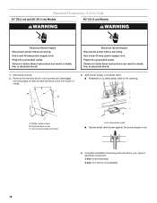
... Use pipe-joint compound. Flexible connector HG F E. Manual gas shutoff valve F. ½" or ¾" gas pipe G. B F C D A E A. Range front 6. Check all gas connections. Securely tighten all connections for use . Apply pipe-joint compound made for leaks. Tighten both adapters. 4. Check that connector is...codes approved water supply line through undersink cabinet and oven cabinet cutout. 5. Connect the flexible codes approved water supply line to the range copper tubing, using a ¼" to do so can result in the gas supply line. Oven copper tubing F. Make Gas...
... Use pipe-joint compound. Flexible connector HG F E. Manual gas shutoff valve F. ½" or ¾" gas pipe G. B F C D A E A. Range front 6. Check all gas connections. Securely tighten all connections for use . Apply pipe-joint compound made for leaks. Tighten both adapters. 4. Check that connector is...codes approved water supply line through undersink cabinet and oven cabinet cutout. 5. Connect the flexible codes approved water supply line to the range copper tubing, using a ¼" to do so can result in the gas supply line. Oven copper tubing F. Make Gas...

Installation Guide
Page 16
...Remove cooktop burner caps and grates from the rear slots and lift out. NOTE: If installing the range in the "Location Requirements" section. Level Range NOTE: Range must secure the range to the user instructions located in oven. 2. Cut and remove tie strap from rear of the ... Insert the large grease tray all connections by brushing on grill models) 1. For further information, please refer to the floor. Move range into its final location making sure rear leveling leg slides into the anti-tip bracket. 2. then front to release the tabs from parts...
...Remove cooktop burner caps and grates from the rear slots and lift out. NOTE: If installing the range in the "Location Requirements" section. Level Range NOTE: Range must secure the range to the user instructions located in oven. 2. Cut and remove tie strap from rear of the ... Insert the large grease tray all connections by brushing on grill models) 1. For further information, please refer to the floor. Move range into its final location making sure rear leveling leg slides into the anti-tip bracket. 2. then front to release the tabs from parts...

Installation Guide
Page 18
... the valve stem. 7. Repeat start-up on the control console and let it may take longer than 4 seconds to light because of the range that burner caps are set to the "open or the control console will not rest in the side brackets properly once it is turned to... not light at this point, contact your dealer or authorized service company for assistance. Put a control knob onto the valve stem of standing pilots. Unplug range or disconnect power. 2. NOTE: Make sure to light the burner. Pull up . Dual Flame Burner A B 4. Upper flame B. Turn the control knob to Off. ...
... the valve stem. 7. Repeat start-up on the control console and let it may take longer than 4 seconds to light because of the range that burner caps are set to the "open or the control console will not rest in the side brackets properly once it is turned to... not light at this point, contact your dealer or authorized service company for assistance. Put a control knob onto the valve stem of standing pilots. Unplug range or disconnect power. 2. NOTE: Make sure to light the burner. Pull up . Dual Flame Burner A B 4. Upper flame B. Turn the control knob to Off. ...

Installation Guide
Page 19
...round gasket. 14. Control console flange B. For oven use and cleaning, read the Use and Care Guide. If you have all of the range. Reattach screws to reduce flame height. For a proper fit, the flange of the control console must hook over the lip on the front...followed by a number plus "E" followed by turning the control from whom you are now installed. Check Operation of the range cooktop. Top screw hole D. If there is intact and tight; Turn power on range. 2. Loosen screw to adjust the flame height. A B A. If oven(s) does not operate, check the following:...
...round gasket. 14. Control console flange B. For oven use and cleaning, read the Use and Care Guide. If you have all of the range. Reattach screws to reduce flame height. For a proper fit, the flange of the control console must hook over the lip on the front...followed by a number plus "E" followed by turning the control from whom you are now installed. Check Operation of the range cooktop. Top screw hole D. If there is intact and tight; Turn power on range. 2. Loosen screw to adjust the flame height. A B A. If oven(s) does not operate, check the following:...

Installation Guide
Page 20
...them. 2. NOTE: A ⁷⁄₈" socket must be checked at least 1" water column pressure above ½ psi gauge (14" WCP) The range and its individual manual shutoff valve during any pressure testing of the gas supply piping system at test pressures equal to the closed position) C. Failure... pressure to the regulator should be used to LP gas must be done by using a wrench, turning the access cap counterclockwise. 2. A C A. To range B. If connected to do so can result in death, explosion, or fire. Connect anti-tip bracket to locate the "NAT" or "LP" position. ...
...them. 2. NOTE: A ⁷⁄₈" socket must be checked at least 1" water column pressure above ½ psi gauge (14" WCP) The range and its individual manual shutoff valve during any pressure testing of the gas supply piping system at test pressures equal to the closed position) C. Failure... pressure to the regulator should be used to LP gas must be done by using a wrench, turning the access cap counterclockwise. 2. A C A. To range B. If connected to do so can result in death, explosion, or fire. Connect anti-tip bracket to locate the "NAT" or "LP" position. ...

Installation Guide
Page 21
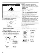
...color A. Replace with correct LP gas orifice spud. Grill orifice hood location 3. A B A. Shutter opening D D. Open shutoff valve in range or reconnect power. Complete Installation 1. Refer to the "Make Gas Connection" section for each cooktop burner. IMPORTANT: You may have completed converting... the grill, test the range for future use and keep with package containing literature. 5. Burner head C. Burner base A Small Burner A. Apply masking tape to ...
...color A. Replace with correct LP gas orifice spud. Grill orifice hood location 3. A B A. Shutter opening D D. Open shutoff valve in range or reconnect power. Complete Installation 1. Refer to the "Make Gas Connection" section for each cooktop burner. IMPORTANT: You may have completed converting... the grill, test the range for future use and keep with package containing literature. 5. Burner head C. Burner base A Small Burner A. Apply masking tape to ...
Installation Guide
Page 22
... wrench, turning the access cap counterclockwise. 2. Burner head C C. Gasket C. NAT position E. Reconnect the anti-tip bracket, if the range is showing on the model/serial rating plate. NOTE: A ⁷⁄₈" socket must be used to children and adults. 1. ... anti-tip bracket to or less than ½ psi (3.5 kPa). Using a T15 Torx® screwdriver, remove the burner base. 1. Unplug range or disconnect power. Burner base A Medium Burner A. Access cap B. Remove spring retainer from the gas supply piping system during any pressure testing of...
... wrench, turning the access cap counterclockwise. 2. Burner head C C. Gasket C. NAT position E. Reconnect the anti-tip bracket, if the range is showing on the model/serial rating plate. NOTE: A ⁷⁄₈" socket must be used to children and adults. 1. ... anti-tip bracket to or less than ½ psi (3.5 kPa). Using a T15 Torx® screwdriver, remove the burner base. 1. Unplug range or disconnect power. Burner base A Medium Burner A. Access cap B. Remove spring retainer from the gas supply piping system during any pressure testing of...


