

Owners Manual
Page 2
Mounting on a table 7 - 2 TABLE OF CONTENTS CONTENTS ENEGNLGISH 3 ASSEMBLING AND PREPAR- ING 3 Unpacking 4 Parts and buttons 5 Setting up the Monitor set . Using the cable holder 9 - Detaching ... 19 -PICTURE MODE 20 -SUPER ENERGY SAVING 21 -DUAL DISPLAY 21 -DUAL WEB 22 -MY KEY SETTING 23 TROUBLESHOOTING 25 SPECIFICATIONS 25 27EA33V 26 Preset Modes (Resolution) 26 Indicator 27 PROPER POSTURE 27 Proper posture for using the Monitor set 5 - Mounting on a wall 10 USING THE MONITOR SET 10 Connecting to a PC 10 -
Mounting on a table 7 - 2 TABLE OF CONTENTS CONTENTS ENEGNLGISH 3 ASSEMBLING AND PREPAR- ING 3 Unpacking 4 Parts and buttons 5 Setting up the Monitor set . Using the cable holder 9 - Detaching ... 19 -PICTURE MODE 20 -SUPER ENERGY SAVING 21 -DUAL DISPLAY 21 -DUAL WEB 22 -MY KEY SETTING 23 TROUBLESHOOTING 25 SPECIFICATIONS 25 27EA33V 26 Preset Modes (Resolution) 26 Indicator 27 PROPER POSTURE 27 Proper posture for using the Monitor set 5 - Mounting on a wall 10 USING THE MONITOR SET 10 Connecting to a PC 10 -
Owners Manual
Page 7
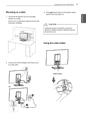
Using the cable holder 2 Connect the AC-DC Adapter and Power Cord to another location. CAUTION Unplug the power cord before moving the Monitor to a wall outlet. or Cable holder Leave a 10 cm (minimum) space from the wall for proper ventilation. 10 cm 10 cm 10 cm 10 cm 3 Press (Power) button on the bottom switch panel to turn the power on a table. Otherwise electric shock may occur. ENEGNLGISH ASSEMBLING AND PREPARING 7 Mounting on a table 1 Lift and tilt the Monitor set into its upright position on .
Using the cable holder 2 Connect the AC-DC Adapter and Power Cord to another location. CAUTION Unplug the power cord before moving the Monitor to a wall outlet. or Cable holder Leave a 10 cm (minimum) space from the wall for proper ventilation. 10 cm 10 cm 10 cm 10 cm 3 Press (Power) button on the bottom switch panel to turn the power on a table. Otherwise electric shock may occur. ENEGNLGISH ASSEMBLING AND PREPARING 7 Mounting on a table 1 Lift and tilt the Monitor set into its upright position on .

Owners Manual
Page 9
...an installation manual and necessary parts. yyUse only screws and wall mounts that are available from your warranty. yyDo not over tighten the screws as this case, LG Electronics is optional. Model VESA (A x B) Standard screw Number of screws 27EA33V 100 x 100 M4 4 10 cm 10 cm 10 ...cm 10 cm If you install the Monitor set . ASSEMBLING AND PREPARING 9 ENEGNLGISH Mounting on a wall For proper ventilation, allow a clearance ...
...an installation manual and necessary parts. yyUse only screws and wall mounts that are available from your warranty. yyDo not over tighten the screws as this case, LG Electronics is optional. Model VESA (A x B) Standard screw Number of screws 27EA33V 100 x 100 M4 4 10 cm 10 cm 10 ...cm 10 cm If you install the Monitor set . ASSEMBLING AND PREPARING 9 ENEGNLGISH Mounting on a wall For proper ventilation, allow a clearance ...


