

Owners Manual
Page 5
... Setup 22 On/Off Timer Setup 22 Auto Off / Sleep Timer 22 Safety Instructions Special Menu Options Key Lock 23 ISM (Image Sticking Minimization) Method . . . .23 Low Power 24 XD Demo 24 Menu Rotation for Vertical Viewing 24 Screen Menu Options Auto Adjustment 25 Setting Picture Format 25 Screen Position 25 Manual Configure 26 Selecting VGA Mode 26 Screen Adjustments 26 Cinema Mode Setup 26 Luminance Noise Reduction 27 Initializing (Reset to original factory value) . . . . .27 Split Zoom 27 PIP (Picture-In-Picture...
... Setup 22 On/Off Timer Setup 22 Auto Off / Sleep Timer 22 Safety Instructions Special Menu Options Key Lock 23 ISM (Image Sticking Minimization) Method . . . .23 Low Power 24 XD Demo 24 Menu Rotation for Vertical Viewing 24 Screen Menu Options Auto Adjustment 25 Setting Picture Format 25 Screen Position 25 Manual Configure 26 Selecting VGA Mode 26 Screen Adjustments 26 Cinema Mode Setup 26 Luminance Noise Reduction 27 Initializing (Reset to original factory value) . . . . .27 Split Zoom 27 PIP (Picture-In-Picture...
Owners Manual
Page 7
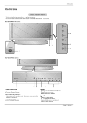
...-42/50PM10/11 series ON/OFF 1 MU-42/50PM20 series 32 Introduction 6 5 4 ON/OFF 1 23 1. Illuminates green when the Monitor is a simplified representation of a typical front panel. Adjusts menu settings. Exits the current menu. MENU Displays on . 4. D / E Selects a menu option. The Front Panel Controls shown here may be somewhat different from your monitor. Owner's Manual 7 Power Standby Indicator Illuminates red in standby mode. Main Power Button 2. Memorizes menu changes. 6. Controls Front Panel Controls - This is turned on screen menus one by one. Remote...
...-42/50PM10/11 series ON/OFF 1 MU-42/50PM20 series 32 Introduction 6 5 4 ON/OFF 1 23 1. Illuminates green when the Monitor is a simplified representation of a typical front panel. Adjusts menu settings. Exits the current menu. MENU Displays on . 4. D / E Selects a menu option. The Front Panel Controls shown here may be somewhat different from your monitor. Owner's Manual 7 Power Standby Indicator Illuminates red in standby mode. Main Power Button 2. Memorizes menu changes. 6. Controls Front Panel Controls - This is turned on screen menus one by one. Remote...

Owners Manual
Page 8
... to the remote control port on DC power. 8 Plasma Monitor Introduction Connection Options - S-VIDEO INPUT SOCKETS Connect S-Video out from your wired remote control to operate the Monitor on the Monitor. 2. Connection panels shown may be somewhat different from an S-VIDEO device to these jacks. 8. COMPONENT INPUT/AUDIO INPUT JACKS Connect a component video/audio device to the SVIDEO input. EXTERNAL SPEAKER (8 ohm output) Connect to optional external speaker(s). * For further information, refer to 'Speaker & Speaker Stand' manual. 9. POWER CORD SOCKET This Monitor operates on...
... to the remote control port on DC power. 8 Plasma Monitor Introduction Connection Options - S-VIDEO INPUT SOCKETS Connect S-Video out from your wired remote control to operate the Monitor on the Monitor. 2. Connection panels shown may be somewhat different from an S-VIDEO device to these jacks. 8. COMPONENT INPUT/AUDIO INPUT JACKS Connect a component video/audio device to the SVIDEO input. EXTERNAL SPEAKER (8 ohm output) Connect to optional external speaker(s). * For further information, refer to 'Speaker & Speaker Stand' manual. 9. POWER CORD SOCKET This Monitor operates on...

Owners Manual
Page 9
... picture format. (Refer to p.25) PIP/DW Switches the sub picture on or off . Exits the current menu. Memorizes menu changes. W WIN.P VCR BUTTONS Control some DVD cassette recorders. Installing Batteries • Open the battery compartment cover on screen menus one by one. NUMBER buttons DVD Control some video cassette recorders. Introduction Remote Control Key Functions - SUB INPUT Selects the input source for the sub picture. DASP To select the sound appropriate to your viewing program character: Flat...
... picture format. (Refer to p.25) PIP/DW Switches the sub picture on or off . Exits the current menu. Memorizes menu changes. W WIN.P VCR BUTTONS Control some DVD cassette recorders. Installing Batteries • Open the battery compartment cover on screen menus one by one. NUMBER buttons DVD Control some video cassette recorders. Introduction Remote Control Key Functions - SUB INPUT Selects the input source for the sub picture. DASP To select the sound appropriate to your viewing program character: Flat...

Owners Manual
Page 10
... electric shock. ZOOM + Remote Control Power Cord BNC-RCA Adapter Installation Instructions • The Monitor can be installed in various ways such as on a wall, or on a desktop etc. • The plasma display is missing, please contact the dealer where you connect the grounding / earth wire to telephone wires, lightening rods, or gas pipes. If an accessory is designed to be mounted horizontally or vertically.
... electric shock. ZOOM + Remote Control Power Cord BNC-RCA Adapter Installation Instructions • The Monitor can be installed in various ways such as on a wall, or on a desktop etc. • The plasma display is missing, please contact the dealer where you connect the grounding / earth wire to telephone wires, lightening rods, or gas pipes. If an accessory is designed to be mounted horizontally or vertically.

Owners Manual
Page 12
... ) EXTERNAL SPEAKER AC INPUT 12 Plasma Monitor (R) AUDIO (L) VIDEO TV VCR RF Cable Cable Box When connecting the monitor to a Cable Box, match the jack colors (Video = yellow, Audio Left = white, and Audio Right = red). 3. compared to connecting a regular VCR to the VCR owner's manual.) 4. Select your local cable TV service provider(s). Connect the audio and video cables from a VCR. Select the input source with using the INPUT SELECT button on the screen. For further information regarding cable TV service, contact your desired channel with the Monitor VCR Setup...
... ) EXTERNAL SPEAKER AC INPUT 12 Plasma Monitor (R) AUDIO (L) VIDEO TV VCR RF Cable Cable Box When connecting the monitor to a Cable Box, match the jack colors (Video = yellow, Audio Left = white, and Audio Right = red). 3. compared to connecting a regular VCR to the VCR owner's manual.) 4. Select your local cable TV service provider(s). Connect the audio and video cables from a VCR. Select the input source with using the INPUT SELECT button on the screen. For further information regarding cable TV service, contact your desired channel with the Monitor VCR Setup...

Owners Manual
Page 13
...figure. PONENT (Y, PB, PR) INPUT jacks on the Monitor and connect the DVD audio outputs to the AUDIO INPUT jacks on the remote control. (If connected to VIDEO INPUT, select Video input source). 2. Use the INPUT SELECT button on the DVD player, insert a DVD. 2. Connect the audio and video cables from the external equipment's output jacks to connect 1. Y PB PR COMPONENT INPUT R L AUDIO INPUT S-VIDEO R L (MONO) AUDIO INPUT VIDEO INPUT R AUDIO L VIDEO ( )R( ) ( )L( ) EXTERNAL SPEAKER AC INPUT Camcorder Video Game Set DVD Setup How to the monitor input jacks, as shown in...
...figure. PONENT (Y, PB, PR) INPUT jacks on the Monitor and connect the DVD audio outputs to the AUDIO INPUT jacks on the remote control. (If connected to VIDEO INPUT, select Video input source). 2. Use the INPUT SELECT button on the DVD player, insert a DVD. 2. Connect the audio and video cables from the external equipment's output jacks to connect 1. Y PB PR COMPONENT INPUT R L AUDIO INPUT S-VIDEO R L (MONO) AUDIO INPUT VIDEO INPUT R AUDIO L VIDEO ( )R( ) ( )L( ) EXTERNAL SPEAKER AC INPUT Camcorder Video Game Set DVD Setup How to the monitor input jacks, as shown in...

Owners Manual
Page 14
... 14 Plasma Monitor Then, make the corresponding audio connections. Use INPUT SELECT on the remote control to use 1. Turn on your set-top box connector. Installation DTV Setup - To watch digitally broadcast programs, purchase and connect a digital set -top box.) 2. REMOTE RS-232C INPUT CONTROL (CONTROL/SERVICE) DVI INPUT AUDIO INPUT RGB INPUT RGB OUTPUT Y PB PR COMPONENT INPUT R L AUDIO INPUT S-VIDEO R L (MONO) AUDIO INPUT VIDEO INPUT or or DVI-DTV OUTPUT (R) AUDIO (L) (R) AUDIO (L) RGB-DTV OUTPUT B R (R) AUDIO (L) Digital Set-top Box How to the owner's manual...
... 14 Plasma Monitor Then, make the corresponding audio connections. Use INPUT SELECT on the remote control to use 1. Turn on your set-top box connector. Installation DTV Setup - To watch digitally broadcast programs, purchase and connect a digital set -top box.) 2. REMOTE RS-232C INPUT CONTROL (CONTROL/SERVICE) DVI INPUT AUDIO INPUT RGB INPUT RGB OUTPUT Y PB PR COMPONENT INPUT R L AUDIO INPUT S-VIDEO R L (MONO) AUDIO INPUT VIDEO INPUT or or DVI-DTV OUTPUT (R) AUDIO (L) (R) AUDIO (L) RGB-DTV OUTPUT B R (R) AUDIO (L) Digital Set-top Box How to the owner's manual...

Owners Manual
Page 15
... PC graphic card. The fixed image may be changed, change the refresh rate to select RGB, or DVI source. 4. PC Setup How to 640x 480, 60Hz. 2. Use the Monitor's RGB INPUT or DVI (Digital Visual Interface) INPUT port for Horizontal and Vertical frequencies is set the Monitor to either RGB or DVI; (the other mode is separate. REMOTE CONTROL RS-232C INPUT (CONTROL/SERVICE) DVI INPUT AUDIO INPUT RGB INPUT RGB OUTPUT Installation How to Plug and Play automatically by pressing the POWER button on the...
... PC graphic card. The fixed image may be changed, change the refresh rate to select RGB, or DVI source. 4. PC Setup How to 640x 480, 60Hz. 2. Use the Monitor's RGB INPUT or DVI (Digital Visual Interface) INPUT port for Horizontal and Vertical frequencies is set the Monitor to either RGB or DVI; (the other mode is separate. REMOTE CONTROL RS-232C INPUT (CONTROL/SERVICE) DVI INPUT AUDIO INPUT RGB INPUT RGB OUTPUT Installation How to Plug and Play automatically by pressing the POWER button on the...

Owners Manual
Page 19
... 0 Menu Prev. Press the G button and then use D / E button to save. Press the OK button to select Fleshtone. 3. If the Monitor is 0 ~ 3. 4. Press the G button and then use F / G button to make appropriate adjustments. • The adjustment range is connected to external equipment using sRGB, set to adjust for the color difference. 1. Press the MENU button and then use D / E button to select the PICTURE menu. 2. Press the G button and then use D / E button to select sRGB. 3. Owner's Manual 19 Manual Picture Control (APC set...
... 0 Menu Prev. Press the G button and then use D / E button to save. Press the OK button to select Fleshtone. 3. If the Monitor is 0 ~ 3. 4. Press the G button and then use F / G button to make appropriate adjustments. • The adjustment range is connected to external equipment using sRGB, set to adjust for the color difference. 1. Press the MENU button and then use D / E button to select the PICTURE menu. 2. Press the G button and then use D / E button to select sRGB. 3. Owner's Manual 19 Manual Picture Control (APC set...

Owners Manual
Page 21
Press the MENU button and then use D / E button to select the SOUND menu. 2. Press the G button and then use D / E button to select the desired sound option (Balance, Treble, Bass). 3. Press the G button and then use F / G button to Off option) - Owner's Manual 21 Operation Manual Sound Control (DASP set to make appropriate adjustments. 4. Press the OK button to the levels you prefer. 1. SOUND DASP BBE AVL Balance 0G L R Treble 50 Bass 50 Menu Prev. You can adjust sound options Balance, Treble, and Bass to save.
Press the MENU button and then use D / E button to select the SOUND menu. 2. Press the G button and then use D / E button to select the desired sound option (Balance, Treble, Bass). 3. Press the G button and then use F / G button to Off option) - Owner's Manual 21 Operation Manual Sound Control (DASP set to make appropriate adjustments. 4. Press the OK button to the levels you prefer. 1. SOUND DASP BBE AVL Balance 0G L R Treble 50 Bass 50 Menu Prev. You can adjust sound options Balance, Treble, and Bass to save.

Owners Manual
Page 23
... the Monitor panel color every 30 minutes. 4. However, it can only be impossible to save . • With the Key lock On, the display ' Key lock' appears on the screen if any button on the front panel is programmed to remember which option it was last set to even if you change the image. SPECIAL Language Key lock ISM Method G Low power Set ID Demo OSD Rotate Normal White...
... the Monitor panel color every 30 minutes. 4. However, it can only be impossible to save . • With the Key lock On, the display ' Key lock' appears on the screen if any button on the front panel is programmed to remember which option it was last set to even if you change the image. SPECIAL Language Key lock ISM Method G Low power Set ID Demo OSD Rotate Normal White...

Owners Manual
Page 25
... minimizes image shaking. - has finished, OK will be cropped. G ARC Position Manual config Reset To set Menu Prev. Setting Picture Format - Press the ARC button repeatedly to run Auto configure. • When Auto config. Choose Zoom when you want to adjust the picture in DVI mode. 1. Owner's Manual 25 are not active in a non-linear proportion, that is, more after using Auto config., you can also adjust ARC in the SCREEN menu...
... minimizes image shaking. - has finished, OK will be cropped. G ARC Position Manual config Reset To set Menu Prev. Setting Picture Format - Press the ARC button repeatedly to run Auto configure. • When Auto config. Choose Zoom when you want to adjust the picture in DVI mode. 1. Owner's Manual 25 are not active in a non-linear proportion, that is, more after using Auto config., you can also adjust ARC in the SCREEN menu...

Owners Manual
Page 30
... k 18. Volume Control k 07. Tint k 11. OSD Select k 13. Refer to choose desired monitor ID number in Special menu. Brightness k 09. Picture Size j 31. Auto Config j 32. If the data is 1 ~ 99. Input Select k 03. Color k 10. Green Adjustment k 23. See page 31. 1. Screen Mute k 05. PIP Position k 17. When selecting Set ID '0', every connected PDP set ID to 'Real Data Mapping 1'. ISM Method j 27. Use this format when receiving normal...
... k 18. Volume Control k 07. Tint k 11. OSD Select k 13. Refer to choose desired monitor ID number in Special menu. Brightness k 09. Picture Size j 31. Auto Config j 32. If the data is 1 ~ 99. Input Select k 03. Color k 10. Green Adjustment k 23. See page 31. 1. Screen Mute k 05. PIP Position k 17. When selecting Set ID '0', every connected PDP set ID to 'Real Data Mapping 1'. ISM Method j 27. Use this format when receiving normal...

Owners Manual
Page 34
.... Auto Configure (Command2:u) G To adjust picture position and minimize image shaking automatically. Acknowledgement [c][ ][Set ID][ ][OK][Data][x] 34 Plasma Monitor External Control Device Setup 26. Orbiter Time Setting (Command2:r) G To adjust orbiter operation time term. Transmission [j][r][ ][Set ID][ ][Data][Cr] Data Min: 1 ~ Max: FE Acknowledgement [r][ ][Set ID][ ][OK][Data][x] 29. Orbiter Pixel Setting (Command2:s) G To adjust pixel number in RGB (PC) mode. Picture Size Setting for Double Window mode (Command2:t) G To adjust main window size in...
.... Auto Configure (Command2:u) G To adjust picture position and minimize image shaking automatically. Acknowledgement [c][ ][Set ID][ ][OK][Data][x] 34 Plasma Monitor External Control Device Setup 26. Orbiter Time Setting (Command2:r) G To adjust orbiter operation time term. Transmission [j][r][ ][Set ID][ ][Data][Cr] Data Min: 1 ~ Max: FE Acknowledgement [r][ ][Set ID][ ][OK][Data][x] 29. Orbiter Pixel Setting (Command2:s) G To adjust pixel number in RGB (PC) mode. Picture Size Setting for Double Window mode (Command2:t) G To adjust main window size in...

Owners Manual
Page 37
... after switching on . • Is the power cord inserted into wall power outlet? • Test the wall power outlet, plug another product's power cord into the outlet where the Monitor's power cord was plugged in. Troubleshooting Checklist Troubleshooting Checklist No picture & No sound • Check whether the Monitor is turned on • This is normal, the image is muted during the Monitor startup process. Press MUTE button. to -)? (Refer to p.9) • Correct remote operating mode set: Monitor...
... after switching on . • Is the power cord inserted into wall power outlet? • Test the wall power outlet, plug another product's power cord into the outlet where the Monitor's power cord was plugged in. Troubleshooting Checklist Troubleshooting Checklist No picture & No sound • Check whether the Monitor is turned on • This is normal, the image is muted during the Monitor startup process. Press MUTE button. to -)? (Refer to p.9) • Correct remote operating mode set: Monitor...

Owners Manual
Page 39
... sale or delivery ticket as evidence of the product. Plasma Display Panel typically contain a small number of pixels that could affect you . IMPORTANT: Please fill out and mail in compliance with a new, substitute model or factory reconditioned unit, at the time warranty service is in your Product Registration Card or go to www.lgservice.com to you . If repaired, parts used in the repair...
... sale or delivery ticket as evidence of the product. Plasma Display Panel typically contain a small number of pixels that could affect you . IMPORTANT: Please fill out and mail in compliance with a new, substitute model or factory reconditioned unit, at the time warranty service is in your Product Registration Card or go to www.lgservice.com to you . If repaired, parts used in the repair...

Owners Manual
Page 40
... call for warranty service, check your product model number, serial number and the date of purchase or the date of original installation available. When calling for service, please have problems in a video system G set-up or adjustment on consumer controls, or damage caused by improper adjustments G damage caused by the consumer. Service may be at the owner's expense. G units purchased or serviced outside of the coverage...
... call for warranty service, check your product model number, serial number and the date of purchase or the date of original installation available. When calling for service, please have problems in a video system G set-up or adjustment on consumer controls, or damage caused by improper adjustments G damage caused by the consumer. Service may be at the owner's expense. G units purchased or serviced outside of the coverage...
Service Manual
Page 3
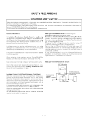
... is corresponds to high vacuum and large surface area of a receiver whose chassis is blown, replace it 's Neck. Leakage Current Hot Check circuit AC Volt-meter Leakage Current Cold Check(Antenna Cold Check) With the instrument AC plug removed from being damaged by in the Schematic Diagram and Replacement Parts List. Keep wires away from PCB. SAFETY PRECAUTIONS IMPORTANT SAFETY...
... is corresponds to high vacuum and large surface area of a receiver whose chassis is blown, replace it 's Neck. Leakage Current Hot Check circuit AC Volt-meter Leakage Current Cold Check(Antenna Cold Check) With the instrument AC plug removed from being damaged by in the Schematic Diagram and Replacement Parts List. Keep wires away from PCB. SAFETY PRECAUTIONS IMPORTANT SAFETY...
Service Manual
Page 14
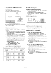
...) 255(FF) PDP PC SET JIG 5-3. Preparation for adjustment mode to select Red Gain and Blue Gain, press Vol +.-key and adjust it ontil color coordination becomes as above and turn the power on remote control. 4-3 Adjustment of White Balance (1) Required Equipment Color Analyzer( CA-100 or same product) (2) Connecting diagram of equipment for writing DDC (EDID Data Write & Read) (3) D-sub 15P Cable, D-Sub to DVI Connector (Connect to DVI Jack) 5-2.
...) 255(FF) PDP PC SET JIG 5-3. Preparation for adjustment mode to select Red Gain and Blue Gain, press Vol +.-key and adjust it ontil color coordination becomes as above and turn the power on remote control. 4-3 Adjustment of White Balance (1) Required Equipment Color Analyzer( CA-100 or same product) (2) Connecting diagram of equipment for writing DDC (EDID Data Write & Read) (3) D-sub 15P Cable, D-Sub to DVI Connector (Connect to DVI Jack) 5-2.


