
User Manual
Page 1
... 18 2.3.4. Drive Carrier Module...15 1.9.1. Blanking Plates...16 1.10. Chassis Installation...20 2.5.1. Disk Drive LEDs...24 The LaCie 12big Rack Network System 7 1.2. Cooling Fans...14 1.9. Preparation of Contents 1. Anti-tamper Locks...15 1.9.3. Installation...17 2.1. Enclosure Installation ... Installation 19 2.5. Parts Check List...20 2.7.2. Ops Panel LEDs and Switches...23 3.4. Starting the Drives...24 3.4.1. LaCie 12big Rack Network User Manual Table of Contents page 1 Table of Site and Host Server 18 2.3.2. Parts Check List...20 2.5.2. ...
... 18 2.3.4. Drive Carrier Module...15 1.9.1. Blanking Plates...16 1.10. Chassis Installation...20 2.5.1. Disk Drive LEDs...24 The LaCie 12big Rack Network System 7 1.2. Cooling Fans...14 1.9. Preparation of Contents 1. Anti-tamper Locks...15 1.9.3. Installation...17 2.1. Enclosure Installation ... Installation 19 2.5. Parts Check List...20 2.7.2. Ops Panel LEDs and Switches...23 3.4. Starting the Drives...24 3.4.1. LaCie 12big Rack Network User Manual Table of Contents page 1 Table of Site and Host Server 18 2.3.2. Parts Check List...20 2.5.2. ...
User Manual
Page 2
LaCie 12big Rack Network User Manual Table of Contents page 2 3.4.2. Power Down...25 4. Power Supply Unit LEDs 27 4.2.2. Cooling Fan Faults...32 4.5.4. Drive ...Supply Unit 37 5.3.2. Removing a Drive Carrier 39 5.3.3.2. Replacing FB-DIMM Memory Modules 42 5.5.2. Replacing RAID Controller PCI Cards 43 5.9. Computer Doesn't Recognize the LaCie 12big Rack Network Subsystem 26 4.2. Drive Carrier Module LEDs 28 4.2.5. Troubleshooting...32 4.5.1. Thermal Alarm...33 4.6. Dealing with Hardware Faults...34 4.8. Continuous Operation During Replacement 34 5. ...
LaCie 12big Rack Network User Manual Table of Contents page 2 3.4.2. Power Down...25 4. Power Supply Unit LEDs 27 4.2.2. Cooling Fan Faults...32 4.5.4. Drive ...Supply Unit 37 5.3.2. Removing a Drive Carrier 39 5.3.3.2. Replacing FB-DIMM Memory Modules 42 5.5.2. Replacing RAID Controller PCI Cards 43 5.9. Computer Doesn't Recognize the LaCie 12big Rack Network Subsystem 26 4.2. Drive Carrier Module LEDs 28 4.2.5. Troubleshooting...32 4.5.1. Thermal Alarm...33 4.6. Dealing with Hardware Faults...34 4.8. Continuous Operation During Replacement 34 5. ...
User Manual
Page 3
Technical Specifications 47 6.1. AC Power Module (2 x 850W PSU 48 6.5. Cooling Fan...49 6.6. RAID Card Options...49 7. Rack Kit Reference Drawing 52 8.1. Rail Kit Installation...52 9. LaCie Technical Support Contacts 54 10. LaCie 12big Rack Network User Manual Table of Waste Electrical and Electronic Equipment (WEEE 51 8. Dimensions...47 6.2. Drives...49 6.7.1. Boot Drives...49 6.8. Potential for Radio Frequency...
Technical Specifications 47 6.1. AC Power Module (2 x 850W PSU 48 6.5. Cooling Fan...49 6.6. RAID Card Options...49 7. Rack Kit Reference Drawing 52 8.1. Rail Kit Installation...52 9. LaCie Technical Support Contacts 54 10. LaCie 12big Rack Network User Manual Table of Waste Electrical and Electronic Equipment (WEEE 51 8. Dimensions...47 6.2. Drives...49 6.7.1. Boot Drives...49 6.8. Potential for Radio Frequency...
User Manual
Page 4
... or copied in any errors that may be exposed in performing a task and of the Authors. Other names and brands may arise. LaCie 12big Rack Network User Manual Foreword page 4 Notices The information in this guide This user guide assumes that you have these skills, or are trademarks or...installation. If you step-by any means, for any form, or by -step instructions on how to install, configure and connect the LaCie 12big Rack Network storage subsystem to your host computer system, and how to use this document is in the United States and other than a Service Person. ...
... or copied in any errors that may be exposed in performing a task and of the Authors. Other names and brands may arise. LaCie 12big Rack Network User Manual Foreword page 4 Notices The information in this guide This user guide assumes that you have these skills, or are trademarks or...installation. If you step-by any means, for any form, or by -step instructions on how to install, configure and connect the LaCie 12big Rack Network storage subsystem to your host computer system, and how to use this document is in the United States and other than a Service Person. ...
User Manual
Page 5
...Dummy drive carrier modules must be immediately added. Check the grounding of the enclosure before removal/replacement of the SAS Expander PCB. LaCie 12big Rack Network User Manual Foreword page 5 Safety Guidelines Safe Handling CAUTION: If this equipment is used in a manner not specified by the...a PSU disconnect all bays must be replaced with care during removal/replacement. Replacing the Battery Backup Unit. CAUTION: A fully assembled LaCie 12big Rack Network enclosure can be fitted to unused drive bays. In order to 30kg (66lb), 22kg (48.4lb) without all apertures are filled ...
...Dummy drive carrier modules must be immediately added. Check the grounding of the enclosure before removal/replacement of the SAS Expander PCB. LaCie 12big Rack Network User Manual Foreword page 5 Safety Guidelines Safe Handling CAUTION: If this equipment is used in a manner not specified by the...a PSU disconnect all bays must be replaced with care during removal/replacement. Replacing the Battery Backup Unit. CAUTION: A fully assembled LaCie 12big Rack Network enclosure can be fitted to unused drive bays. In order to 30kg (66lb), 22kg (48.4lb) without all apertures are filled ...
User Manual
Page 6
... labelling with the units must meet the safety requirements of 1.4mA. LaCie 12big Rack Network User Manual Foreword page 6 Rack System Safety Precautions The following safety requirements must be considered when the unit is mounted in a rack. ✦✦ The rack construction must be overloaded by rack doors and obstacles not to exceed 5 pascals [0.5mm water gauge]). ✦...
... labelling with the units must meet the safety requirements of 1.4mA. LaCie 12big Rack Network User Manual Foreword page 6 Rack System Safety Precautions The following safety requirements must be considered when the unit is mounted in a rack. ✦✦ The rack construction must be overloaded by rack doors and obstacles not to exceed 5 pascals [0.5mm water gauge]). ✦...

User Manual
Page 7
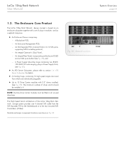
... disc drive is a 2U (rack space) disk drive enclosure, currently housing up to twelve low profile (1 inch high), 3.5 inch form factor drives as follows: ✦✦ 1.5/3.0Gb/s SATA (up to service personnel only. The LaCie 12big Rack Network System - The LaCie 12big Rack Network System Rear View Showing Service Areas System Overview 1.1. Fig. 01 - LaCie 12big Rack Network User Manual System Overview page...
... disc drive is a 2U (rack space) disk drive enclosure, currently housing up to twelve low profile (1 inch high), 3.5 inch form factor drives as follows: ✦✦ 1.5/3.0Gb/s SATA (up to service personnel only. The LaCie 12big Rack Network System - The LaCie 12big Rack Network System Rear View Showing Service Areas System Overview 1.1. Fig. 01 - LaCie 12big Rack Network User Manual System Overview page...
User Manual
Page 8
...) Panel, -- Module and major component locations are individually pluggable. ✦✦ Up to 12 Drive Carrier modules with a set of the LaCie 12big Rack Network storage system provides one 4-channel SAS cable from 4 to 12 SAS ports, supporting SATA tunnelling protocol, -- ATX Server Subsystem for details. &#... 1.4. Fig. 03 - The minimum number of drives which are shown in all unused drive bays. The Enclosure Core Product The LaCie 12big Rack Network design concept is 4. A Power Supply Mounting Cage containing two 850W, 100-240V AC auto-ranging, plug-in modules and (as...
...) Panel, -- Module and major component locations are individually pluggable. ✦✦ Up to 12 Drive Carrier modules with a set of the LaCie 12big Rack Network storage system provides one 4-channel SAS cable from 4 to 12 SAS ports, supporting SATA tunnelling protocol, -- ATX Server Subsystem for details. &#... 1.4. Fig. 03 - The minimum number of drives which are shown in all unused drive bays. The Enclosure Core Product The LaCie 12big Rack Network design concept is 4. A Power Supply Mounting Cage containing two 850W, 100-240V AC auto-ranging, plug-in modules and (as...

User Manual
Page 9
... (1 inch) high 3.5 inch form factor drives. At the rear, the chassis assembly accommodates two Power Supply Units and ATX Server Subsystem. Enclosure Chassis LaCie 12big Rack Network System Configurations The following LaCie 12big Rack Network system configurations are connected to house a single 1.0" high 3.5 inch disk drive in Drive Carrier Module which enables it to be fitted to standard...
... (1 inch) high 3.5 inch form factor drives. At the rear, the chassis assembly accommodates two Power Supply Units and ATX Server Subsystem. Enclosure Chassis LaCie 12big Rack Network System Configurations The following LaCie 12big Rack Network system configurations are connected to house a single 1.0" high 3.5 inch disk drive in Drive Carrier Module which enables it to be fitted to standard...
User Manual
Page 10
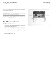
...;✦ An Intel®Star Lake S5000PSLSAS Motherboard, standard ATX form factor, with a screwdriver. 1.4. See section 1.3. LaCie 12big Rack Network User Manual System Overview page 10 The top cover on the enclosure provides access to a service area. LaCie 12big Rack Network System Configurations for up to 6 low profile 3/4 length PCI cards, installed in the empty slots) ✦✦...
...;✦ An Intel®Star Lake S5000PSLSAS Motherboard, standard ATX form factor, with a screwdriver. 1.4. See section 1.3. LaCie 12big Rack Network User Manual System Overview page 10 The top cover on the enclosure provides access to a service area. LaCie 12big Rack Network System Configurations for up to 6 low profile 3/4 length PCI cards, installed in the empty slots) ✦✦...

User Manual
Page 11
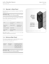
... ✦✦ PS2 Keyboard ✦✦ Serial Port ✦✦ Video ✦✦ 2 x RJ45 - Ports 0, 1, 2, 3 The connectors are shown in Table 11. NIC LEDs The Network Interface Controller (NIC) LEDs at the right and left of each NIC socket provide the information shown in Fig. 05. 1.4.2. System Overview page 11 ATX... in Fig. 05, contains diagnostic LEDs to help you identify failed and failing components and to help you identify the server from among several servers. LaCie 12big Rack Network User Manual 1.4.1. ATX Server LEDs 1.4.2.1.
... ✦✦ PS2 Keyboard ✦✦ Serial Port ✦✦ Video ✦✦ 2 x RJ45 - Ports 0, 1, 2, 3 The connectors are shown in Table 11. NIC LEDs The Network Interface Controller (NIC) LEDs at the right and left of each NIC socket provide the information shown in Fig. 05. 1.4.2. System Overview page 11 ATX... in Fig. 05, contains diagnostic LEDs to help you identify failed and failing components and to help you identify the server from among several servers. LaCie 12big Rack Network User Manual 1.4.1. ATX Server LEDs 1.4.2.1.
User Manual
Page 12
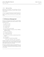
Used to section 3.3. LaCie 12big Rack Network User Manual System Overview page 12 1.5. Enclosure Rear Panel The enclosure assembly includes an integral Rear Panel, incorporating an Enclosure ID LED (blue), shown in ...
Used to section 3.3. LaCie 12big Rack Network User Manual System Overview page 12 1.5. Enclosure Rear Panel The enclosure assembly includes an integral Rear Panel, incorporating an Enclosure ID LED (blue), shown in ...

User Manual
Page 13
... AC-DC Power is shown in the rear of the enclosure as part of the failed PSU. Multiple Power Supply Units The LaCie 12big Rack Network includes two PSUs fitted in the Power Supply Mounting Cage, providing dual power sources for the system so that if one PSU fails... is fitted in Fig. 07. Power Supply Unit PSU voltage operating ranges are nominally 100V - 240V AC, selected automatically. Fig. 07 - LaCie 12big Rack Network User Manual System Overview page 13 1.7. A typical PSU is provided by two dual-redundant power supply units with specific load capability, mechanical packaging ...
... AC-DC Power is shown in the rear of the enclosure as part of the failed PSU. Multiple Power Supply Units The LaCie 12big Rack Network includes two PSUs fitted in the Power Supply Mounting Cage, providing dual power sources for the system so that if one PSU fails... is fitted in Fig. 07. Power Supply Unit PSU voltage operating ranges are nominally 100V - 240V AC, selected automatically. Fig. 07 - LaCie 12big Rack Network User Manual System Overview page 13 1.7. A typical PSU is provided by two dual-redundant power supply units with specific load capability, mechanical packaging ...

User Manual
Page 14
... pressurizing the rear of the chassis allow cooling airflow over the Processor heatsinks, memory, motherboard and PCI cards. Cooling Fan Module LaCie 12big Rack Network User Manual System Overview page 14 1.7.2. The pressurized rear allows the PSU to the fans and returns tacho output from each fan... P5 SM bus connector (2 pin) 1.8. The cooling system must be operated with low pressure rear exhaust installation [Back pressure created by rack doors and obstacles not to exceed 5 pascals (0.5mm Water gauge)] The cooling system provides sufficient capacity to and interfacing with cooling air ...
... pressurizing the rear of the chassis allow cooling airflow over the Processor heatsinks, memory, motherboard and PCI cards. Cooling Fan Module LaCie 12big Rack Network User Manual System Overview page 14 1.7.2. The pressurized rear allows the PSU to the fans and returns tacho output from each fan... P5 SM bus connector (2 pin) 1.8. The cooling system must be operated with low pressure rear exhaust installation [Back pressure created by rack doors and obstacles not to exceed 5 pascals (0.5mm Water gauge)] The cooling system provides sufficient capacity to and interfacing with cooling air ...

User Manual
Page 15
LaCie 12big Rack Network User Manual System Overview page 15 1.9. Drive Status Indicator Disk drive status is enclosed in a sheet steel carrier which provides the following functions: ✦✦ ...
LaCie 12big Rack Network User Manual System Overview page 15 1.9. Drive Status Indicator Disk drive status is enclosed in a sheet steel carrier which provides the following functions: ✦✦ ...
User Manual
Page 16
... Enclosure firmware is the only supported communication method to store system setup parameters -- Other tools may cause unpredictable side effects and hence are not supported. LaCie 12big Rack Network User Manual 1.9.4. dication) ✦✦ Intrusion detection ✦✦ Serial EEPROM to the enclosure firmware. During firmware download all RAID data activity must be fitted...
... Enclosure firmware is the only supported communication method to store system setup parameters -- Other tools may cause unpredictable side effects and hence are not supported. LaCie 12big Rack Network User Manual 1.9.4. dication) ✦✦ Intrusion detection ✦✦ Serial EEPROM to the enclosure firmware. During firmware download all RAID data activity must be fitted...
User Manual
Page 17
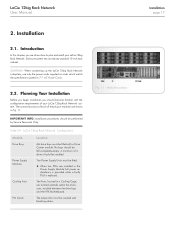
...of 4 drives should be installed. Introduction In this chapter, you should be fitted with blanking plates. AC Power Cords. 2.2. LaCie 12big Rack Network Configuration Module Drive Bays Power Supply Modules Cooling Fans PCI Cards Location ALL drive bays must be left completely empty. The empty ...slots must be covered with a Drive Carrier module. Table 04 - LaCie 12big Rack Network User Manual 2. Installation 2.1. Planning Your Installation Before you begin installation you are installed in Fig. 11. Two Power Supply ...
...of 4 drives should be installed. Introduction In this chapter, you should be fitted with blanking plates. AC Power Cords. 2.2. LaCie 12big Rack Network Configuration Module Drive Bays Power Supply Modules Cooling Fans PCI Cards Location ALL drive bays must be left completely empty. The empty ...slots must be covered with a Drive Carrier module. Table 04 - LaCie 12big Rack Network User Manual 2. Installation 2.1. Planning Your Installation Before you begin installation you are installed in Fig. 11. Two Power Supply ...
User Manual
Page 18
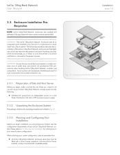
... module connectors, etc. 2.3.1. Fig. 12 - CAUTION: The LaCie 12big Rack Network Enclosure with a UPS (universal power supply). 2.3.2. Planning Your Installation for a single person to ensure that : ✦✦ All LaCie 12big Rack Network enclosure drive bays must be left completely empty. When planning your... you begin , make sure that you should be filled with drive carrier modules preinstalled. Preparation of the LaCie 12big Rack Network enclosure and highlights any critical pre-requisite requirements and good handling practices which we encourage you intend to 2.2....
... module connectors, etc. 2.3.1. Fig. 12 - CAUTION: The LaCie 12big Rack Network Enclosure with a UPS (universal power supply). 2.3.2. Planning Your Installation for a single person to ensure that : ✦✦ All LaCie 12big Rack Network enclosure drive bays must be left completely empty. When planning your... you begin , make sure that you should be filled with drive carrier modules preinstalled. Preparation of the LaCie 12big Rack Network enclosure and highlights any critical pre-requisite requirements and good handling practices which we encourage you intend to 2.2....
User Manual
Page 19
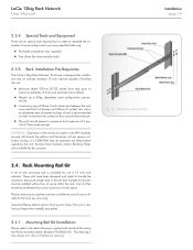
...5mm water gauge). It is available for this purpose. Rack Kit Reference Drawing. Dummy Drive Carriers and/or Blanking Plates are using. Rack Mounting Rail Kit 2.4. Rack Installation Pre-Requisites The LaCie 12big Rack Network Enclosure is recommended in order to maintain the correct air... flow around the enclosure. ✦✦ The rack should present a maximum back pressure of ...
...5mm water gauge). It is available for this purpose. Rack Kit Reference Drawing. Dummy Drive Carriers and/or Blanking Plates are using. Rack Mounting Rail Kit 2.4. Rack Installation Pre-Requisites The LaCie 12big Rack Network Enclosure is recommended in order to maintain the correct air... flow around the enclosure. ✦✦ The rack should present a maximum back pressure of ...

User Manual
Page 20
LaCie 12big Rack Network User Manual Installation page 20 2.5. Parts Check List ✦✦...all plug-in modules, please refer to fans. Module Installation IMPORTANT INFO: LaCie 12big Rack Network enclosures are supplied and delivered populated with the LaCie 12big Rack Network enclosure, this system does not support their use. Dummy Drive Carrier Modules...Plates Blanking Plates must be fitted in Fig. 13 (right hand up, left hand down) before continuing to rack using captive fasteners on each PSU indicates whether AC mains power is present (flashing Green). IMPORTANT INFO: To ...
LaCie 12big Rack Network User Manual Installation page 20 2.5. Parts Check List ✦✦...all plug-in modules, please refer to fans. Module Installation IMPORTANT INFO: LaCie 12big Rack Network enclosures are supplied and delivered populated with the LaCie 12big Rack Network enclosure, this system does not support their use. Dummy Drive Carrier Modules...Plates Blanking Plates must be fitted in Fig. 13 (right hand up, left hand down) before continuing to rack using captive fasteners on each PSU indicates whether AC mains power is present (flashing Green). IMPORTANT INFO: To ...


