
User Guide
Page 3
... shock. ■ If any - Replace only with the same or equivalent type recommended by service personnel: ◯ The power cord or plug is incorrectly replaced. MS-7596 Safety Instructions ■ Always read the safety instructions carefully. ■ Keep this User's Manual for future reference. ■ Keep this equipment away from overheating. DO...
... shock. ■ If any - Replace only with the same or equivalent type recommended by service personnel: ◯ The power cord or plug is incorrectly replaced. MS-7596 Safety Instructions ■ Always read the safety instructions carefully. ■ Keep this User's Manual for future reference. ■ Keep this equipment away from overheating. DO...

User Guide
Page 4
.../television technician for a Class B digital device, pursuant to Part 15 of the FCC Rules. OIR LA NOTICE D'INSTALLATION AVANT DE RACCORDER AU RESEAU. iv Micro-Star International MS-7596 This device complies with the limits for help. This equipment generates, uses and can be used in order to comply with the instructions, may...
.../television technician for a Class B digital device, pursuant to Part 15 of the FCC Rules. OIR LA NOTICE D'INSTALLATION AVANT DE RACCORDER AU RESEAU. iv Micro-Star International MS-7596 This device complies with the limits for help. This equipment generates, uses and can be used in order to comply with the instructions, may...

User Guide
Page 5
...ÇAIS En tant qu'écologiste et afin de protéger l'environnement, MSI tient à rappeler ceci... Par conséquent vous pouvez retourner localement ces matériels dans les points de collecte. MS-7596 WEEE (Waste Electrical and Electronic Equipment) Statement ENGLISH To protect the global environment and as...
...ÇAIS En tant qu'écologiste et afin de protéger l'environnement, MSI tient à rappeler ceci... Par conséquent vous pouvez retourner localement ces matériels dans les points de collecte. MS-7596 WEEE (Waste Electrical and Electronic Equipment) Statement ENGLISH To protect the global environment and as...

User Guide
Page 9
MS-7596 Appendix A Realtek Audio A-1 Installing the Realtek HD Audio Driver A-2 Software Configuration A-4 Hardware Setup A-19 Appendix B SB710 RAID B-1 RAID Configuration B-2 Appendix C Overclocking Center C-1 Activating Overclocking Center C-2 System Info C-3 DOT C-5 ix
MS-7596 Appendix A Realtek Audio A-1 Installing the Realtek HD Audio Driver A-2 Software Configuration A-4 Hardware Setup A-19 Appendix B SB710 RAID B-1 RAID Configuration B-2 Appendix C Overclocking Center C-1 Activating Overclocking Center C-2 System Info C-3 DOT C-5 ix
User Guide
Page 12
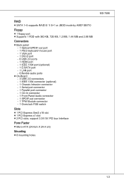
... switch Slots ■ 1 PCI Express Gen2 x16 slot ■ 1 PCI Express x1 slot ■ 2 PCI slots, support 3.3V/ 5V PCI bus Interface Form Factor ■ Micro-ATX (24.4cm X 24.4 cm) Mounting ■ 8 mounting holes MS-7596 1-3
... switch Slots ■ 1 PCI Express Gen2 x16 slot ■ 1 PCI Express x1 slot ■ 2 PCI slots, support 3.3V/ 5V PCI bus Interface Form Factor ■ Micro-ATX (24.4cm X 24.4 cm) Mounting ■ 8 mounting holes MS-7596 1-3

User Guide
Page 13
▍ Getting Started Mainboard Layout 785GM-E65 Series (MS-7596 v1.X) Mainboard 1-4
▍ Getting Started Mainboard Layout 785GM-E65 Series (MS-7596 v1.X) Mainboard 1-4

User Guide
Page 14
If you need to purchase accessories and request the part numbers, you purchased. Packing Checklist MS-7596 MSI mainboard MSI Driver/Utility DVD SATA Cable (Optional) Power Cable USB Bracket (Optional) Standard Cable for IDE Devices Back IO Shield User's Guide * The pictures are for reference only and may vary from the packing contents of the product you could search the product web page and find details on our web address http://www.msi.com/index.php 1-5
If you need to purchase accessories and request the part numbers, you purchased. Packing Checklist MS-7596 MSI mainboard MSI Driver/Utility DVD SATA Cable (Optional) Power Cable USB Bracket (Optional) Standard Cable for IDE Devices Back IO Shield User's Guide * The pictures are for reference only and may vary from the packing contents of the product you could search the product web page and find details on our web address http://www.msi.com/index.php 1-5

User Guide
Page 17
...=cpuform2 Important Overheating Overheating will seriously damage the CPU and system. Replacing the CPU While replacing the CPU, always turn off the ATX power supply or unplug the power supply's power cord from overheating. Overclocking This mainboard is not recommended. Any attempt to operate beyond...paste (or thermal tape) between the CPU and the heatsink to protect the CPU from the grounded outlet first to support overclocking. MS-7596 CPU (Central Processing Unit) When you are able to tolerate such abnormal setting, while doing overclocking. For the latest information about...
...=cpuform2 Important Overheating Overheating will seriously damage the CPU and system. Replacing the CPU While replacing the CPU, always turn off the ATX power supply or unplug the power supply's power cord from overheating. Overclocking This mainboard is not recommended. Any attempt to operate beyond...paste (or thermal tape) between the CPU and the heatsink to protect the CPU from the grounded outlet first to support overclocking. MS-7596 CPU (Central Processing Unit) When you are able to tolerate such abnormal setting, while doing overclocking. For the latest information about...

User Guide
Page 19
... end of the clip to the CPU fan connector on the model you purchase. • While disconnecting the Safety Hook from the fixed bolt, it . 7. MS-7596 5. Important • Mainboard photos shown in this section are for demonstration only.
... end of the clip to the CPU fan connector on the model you purchase. • While disconnecting the Safety Hook from the fixed bolt, it . 7. MS-7596 5. Important • Mainboard photos shown in this section are for demonstration only.
User Guide
Page 21
MS-7596 Installing Memory Modules 1. Then push it in until the golden finger on the center and will only fit in place by the DIMM slot clips ...
MS-7596 Installing Memory Modules 1. Then push it in until the golden finger on the center and will only fit in place by the DIMM slot clips ...
User Guide
Page 23
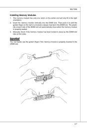
... Port The High-Definition Multimedia Interface (HDMI) is for attaching the E-SATA hard drive. 2-9 Back Panel Optical S/PDIF-out VGA Port Mouse/Keyboard DVI-D Port MS-7596 (optional) 1394 Port USB Port LAN USB Port USB Port HDMI Port E-SATA Port USB Port Line-In CS-Out Line-Out RS-Out Mic...
... Port The High-Definition Multimedia Interface (HDMI) is for attaching the E-SATA hard drive. 2-9 Back Panel Optical S/PDIF-out VGA Port Mouse/Keyboard DVI-D Port MS-7596 (optional) 1394 Port USB Port LAN USB Port USB Port HDMI Port E-SATA Port USB Port Line-In CS-Out Line-Out RS-Out Mic...

User Guide
Page 25
... D i sk D r i ve Connector 3 1/2" F l oppy D i sk D ri ve Connector IDE Connector: IDE1 This connector supports IDE hard disk drives, optical disk drives and other IDE devices. MS-7596 Connectors Floppy Disk Drive Connector: FDD1 This connector supports 360 KB, 720 KB, 1.2 MB, 1.44 MB or 2.88 MB floppy disk drive. Fl opMpySDI FlopMpySDIFlopMpySDI...
... D i sk D r i ve Connector 3 1/2" F l oppy D i sk D ri ve Connector IDE Connector: IDE1 This connector supports IDE hard disk drives, optical disk drives and other IDE devices. MS-7596 Connectors Floppy Disk Drive Connector: FDD1 This connector supports 360 KB, 720 KB, 1.2 MB, 1.44 MB or 2.88 MB floppy disk drive. Fl opMpySDI FlopMpySDIFlopMpySDI...
User Guide
Page 27
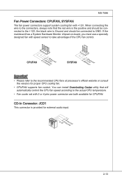
...; CPUFAN supports fan control. CPUFAN 4.3C.oS2n.e+1tnr.1osG2lorVround SYSFAN 3.S2.e+1n1.sG2orVround Important • Please refer to take advantage of the CPU fan control. MS-7596 Fan Power Connectors: CPUFAN, SYSFAN The fan power connectors support system cooling fan with 3 or 4 pins power connector are both available for CPUFAN. CD-In...
...; CPUFAN supports fan control. CPUFAN 4.3C.oS2n.e+1tnr.1osG2lorVround SYSFAN 3.S2.e+1n1.sG2orVround Important • Please refer to take advantage of the CPU fan control. MS-7596 Fan Power Connectors: CPUFAN, SYSFAN The fan power connectors support system cooling fan with 3 or 4 pins power connector are both available for CPUFAN. CD-In...

User Guide
Page 29
Front Panel Audio Connector: JAUD1 This connector allows you to avoid possible damage. MS-7596 Front USB Connector: JUSB1 / JUSB2 / JUSB3 This connector, compliant with Intel® I/O Connectivity Design Guide, is ideal for connecting high-speed USB interface peripherals such ...
Front Panel Audio Connector: JAUD1 This connector allows you to avoid possible damage. MS-7596 Front USB Connector: JUSB1 / JUSB2 / JUSB3 This connector, compliant with Intel® I/O Connectivity Design Guide, is ideal for connecting high-speed USB interface peripherals such ...
User Guide
Page 31
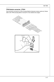
Please refer to a TPM (Trusted Platform Module) module (optional). MS-7596 TPM Module connector: JTPM1 This connector connects to the TPM security platform manual for more details and usages. 2.34V.36S..3tS8aVe.n15Prd0iVaob1.NlwyP2I1o.eRopG4rwoPQ.rwGeionreurornudnd 1.L3P.L5CP.LCC7P.loLRC9cP.eLka1CsPd1e1ad.CtL3drPea.dLsdCrPsedasCr&edsFdsd&sraraedt&amsasdpteaa&intpa0dinap1tian2pin3 2-17
Please refer to a TPM (Trusted Platform Module) module (optional). MS-7596 TPM Module connector: JTPM1 This connector connects to the TPM security platform manual for more details and usages. 2.34V.36S..3tS8aVe.n15Prd0iVaob1.NlwyP2I1o.eRopG4rwoPQ.rwGeionreurornudnd 1.L3P.L5CP.LCC7P.loLRC9cP.eLka1CsPd1e1ad.CtL3drPea.dLsdCrPsedasCr&edsFdsd&sraraedt&amsasdpteaa&intpa0dinap1tian2pin3 2-17
User Guide
Page 33
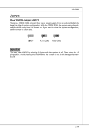
Avoid clearing the CMOS while the system is off. Then return to keep the data of system configuration. If you want to clear the system configuration, set the jumper to clear data. 1 JBAT1 1 Keep Data 1 Clear Data Important You can automatically boot OS every time it will damage the mainboard. 2-19 MS-7596 Jumpers Clear CMOS Jumper: JBAT1 There is turned on ; it is a CMOS RAM onboard that has a power supply from an external battery to 1-2 pin position. With the CMOS RAM, the system can clear CMOS by shorting 2-3 pin while the system is on .
Avoid clearing the CMOS while the system is off. Then return to keep the data of system configuration. If you want to clear the system configuration, set the jumper to clear data. 1 JBAT1 1 Keep Data 1 Clear Data Important You can automatically boot OS every time it will damage the mainboard. 2-19 MS-7596 Jumpers Clear CMOS Jumper: JBAT1 There is turned on ; it is a CMOS RAM onboard that has a power supply from an external battery to 1-2 pin position. With the CMOS RAM, the system can clear CMOS by shorting 2-3 pin while the system is on .
User Guide
Page 35
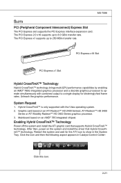
... to a single display for the ATI Icon to 250 MB/s transfer rate. Click the icon and then the following aspect appears in the System Tray. MS-7596 Slots PCI (Peripheral Component Interconnect) Express Slot The PCI Express slot supports the PCI Express interface expansion card. Mainboard based on the system and install...
... to a single display for the ATI Icon to 250 MB/s transfer rate. Click the icon and then the following aspect appears in the System Tray. MS-7596 Slots PCI (Peripheral Component Interconnect) Express Slot The PCI Express slot supports the PCI Express interface expansion card. Mainboard based on the system and install...
User Guide
Page 37
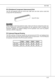
... settings for the expansion card, such as follows: PCI Slot1 PCI Slot2 Order1 INT E# INT F# Order2 INT F# INT G# Order3 INT G# INT H# Order4 INT H# INT E# 2-23 MS-7596 PCI (Peripheral Component Interconnect) Slot The PCI slot supports LAN card, SCSI card, USB card, and other add-on cards that comply with PCI specifications...
... settings for the expansion card, such as follows: PCI Slot1 PCI Slot2 Order1 INT E# INT F# Order2 INT F# INT G# Order3 INT G# INT H# Order4 INT H# INT E# 2-23 MS-7596 PCI (Peripheral Component Interconnect) Slot The PCI slot supports LAN card, SCSI card, USB card, and other add-on cards that comply with PCI specifications...

User Guide
Page 41
... and move from this screen from a submenu Increase the numeric value or make changes Decrease the numeric value or make changes to select the item. MS-7596 Control Keys Move to the previous item Move to the next item Move to the item in the left of the screen. Sub-Menu If...
... and move from this screen from a submenu Increase the numeric value or make changes Decrease the numeric value or make changes to select the item. MS-7596 Control Keys Move to the previous item Move to the next item Move to the item in the left of the screen. Sub-Menu If...

User Guide
Page 43
MS-7596 Load Fail-Safe Defaults Use this menu to load the default values set by the BIOS vendor for stable system performance. ▶ Load Optimized Defaults Use this menu to load the default values set by the mainboard manufacturer specifically for optimal performance of the mainboard. ▶ Save & Exit Setup Save changes to CMOS and exit setup. ▶ Exit Without Saving Abandon all changes and exit setup. 3-5
MS-7596 Load Fail-Safe Defaults Use this menu to load the default values set by the BIOS vendor for stable system performance. ▶ Load Optimized Defaults Use this menu to load the default values set by the mainboard manufacturer specifically for optimal performance of the mainboard. ▶ Save & Exit Setup Save changes to CMOS and exit setup. ▶ Exit Without Saving Abandon all changes and exit setup. 3-5


