User Manual
Page 13
... 34 JAUD1: Front Audio Connector 35 JCI1: Chassis Intrusion Connector 35 JTPM1: TPM Module Connector 36 JLPT1: Parallel Port Connector 36 JBAT1: Clear CMOS (Reset BIOS) Jumper 37 JTBT1: Thunderbolt Add-on Card Connector 37 EZ Debug LED...38 Contents 13
... 34 JAUD1: Front Audio Connector 35 JCI1: Chassis Intrusion Connector 35 JTPM1: TPM Module Connector 36 JLPT1: Parallel Port Connector 36 JBAT1: Clear CMOS (Reset BIOS) Jumper 37 JTBT1: Thunderbolt Add-on Card Connector 37 EZ Debug LED...38 Contents 13
User Manual
Page 14
BIOS Setup ...39 Entering BIOS Setup 39 Resetting BIOS...40 Updating BIOS...40 EZ Mode ...41 Advanced Mode ...43 SETTINGS...44 Advanced...44 Boot...50 Security ...51 Save & Exit...52 OC...53 M-FLASH ...60 OC PROFILE ...61 ... 63 Installing Windows® 10 63 Installing Drivers 63 Installing Utilities 63 APP MANAGER ...64 LIVE UPDATE 6...65 COMMAND CENTER 67 X-BOOST ...71 MYSTICLIGHT...73 MSI SMART TOOL 75 RAMDISK...77 NETWORK GENIE 78 Intel® Extreme Tuning Utility 80 CPU-Z...81 RAID Configuration 82 Using Intel® Rapid Storage Technology...
BIOS Setup ...39 Entering BIOS Setup 39 Resetting BIOS...40 Updating BIOS...40 EZ Mode ...41 Advanced Mode ...43 SETTINGS...44 Advanced...44 Boot...50 Security ...51 Save & Exit...52 OC...53 M-FLASH ...60 OC PROFILE ...61 ... 63 Installing Windows® 10 63 Installing Drivers 63 Installing Utilities 63 APP MANAGER ...64 LIVE UPDATE 6...65 COMMAND CENTER 67 X-BOOST ...71 MYSTICLIGHT...73 MSI SMART TOOL 75 RAMDISK...77 NETWORK GENIE 78 Intel® Extreme Tuning Utility 80 CPU-Z...81 RAID Configuration 82 Using Intel® Rapid Storage Technology...
User Manual
Page 17
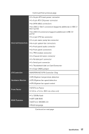
... y CPU/System temperature detection y CPU/System fan speed detection y CPU/System fan speed control From Factor y ATX Form Factor y 12.0 in . (30.5 cm x 24.4 cm) BIOS Features y 1x 128 Mb flash y UEFI AMI BIOS y ACPI 6.0, SM BIOS 3.0 y Multi-language Continued on next page Specifications 17 x 9.6 in .
... y CPU/System temperature detection y CPU/System fan speed detection y CPU/System fan speed control From Factor y ATX Form Factor y 12.0 in . (30.5 cm x 24.4 cm) BIOS Features y 1x 128 Mb flash y UEFI AMI BIOS y ACPI 6.0, SM BIOS 3.0 y Multi-language Continued on next page Specifications 17 x 9.6 in .

User Manual
Page 19
Special Features Continued from previous page y Audio ƒ Audio Boost y Network ƒ Realtek LAN with Network Genie y Storage ƒ Turbo M.2 y Fan ƒ Pump Fan ƒ Smart Fan Control y LED ƒ Mystic Light ƒ Mystic light SYNC ƒ EZ debug LED y Protection ƒ PCIe Steel Armor y Performance ƒ Multi GPU-CrossFire Technology ƒ DDR4 Boost y Stability ƒ Military Class 5 y VR ƒ VR Ready y BIOS ƒ Click BIOS y Certification ƒ Quadro Ready Specifications 19
Special Features Continued from previous page y Audio ƒ Audio Boost y Network ƒ Realtek LAN with Network Genie y Storage ƒ Turbo M.2 y Fan ƒ Pump Fan ƒ Smart Fan Control y LED ƒ Mystic Light ƒ Mystic light SYNC ƒ EZ debug LED y Protection ƒ PCIe Steel Armor y Performance ƒ Multi GPU-CrossFire Technology ƒ DDR4 Boost y Stability ƒ Military Class 5 y VR ƒ VR Ready y BIOS ƒ Click BIOS y Certification ƒ Quadro Ready Specifications 19

User Manual
Page 25
... Connectors CPU_PWR1, ATX_PWR1 Power Connectors CPU Socket LGA1151 CPU Socket DIMMA1/ A2/ B1/ B2 DIMM Slots JAUD1 JBAT1 JCI1 Front Audio Connector Clear CMOS (Reset BIOS) Jumper Chassis Intrusion Connector JCOM1 Serial Port Connector JFP1, JFP2 Front Panel Connectors JLPT1 JTBT1 JTPM1 Parallel Port Connector Thunderbolt Add-on Card Connector TPM...
... Connectors CPU_PWR1, ATX_PWR1 Power Connectors CPU Socket LGA1151 CPU Socket DIMMA1/ A2/ B1/ B2 DIMM Slots JAUD1 JBAT1 JCI1 Front Audio Connector Clear CMOS (Reset BIOS) Jumper Chassis Intrusion Connector JCOM1 Serial Port Connector JFP1, JFP2 Front Panel Connectors JLPT1 JTBT1 JTPM1 Parallel Port Connector Thunderbolt Add-on Card Connector TPM...
User Manual
Page 27
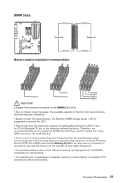
... Windows OS due to the memory frequency operates dependent on installed CPU and devices when overclocking. to set the memory frequency if you want to BIOS and find the Memory Try It! y Due to chipset resource usage, the available capacity of memory will be a little less than the marked value when...
... Windows OS due to the memory frequency operates dependent on installed CPU and devices when overclocking. to set the memory frequency if you want to BIOS and find the Memory Try It! y Due to chipset resource usage, the available capacity of memory will be a little less than the marked value when...
User Manual
Page 34
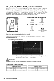
... pin definition 1 Ground 2 Voltage Control 3 Sense 4 NC 34 Overview of the fan speed that allow you plug a 3-pin (Non-PWM) fan to a fan connector in BIOS > HARDWARE MONITOR. When you to adjust fan speed in relation to PWM or DC Mode.
... pin definition 1 Ground 2 Voltage Control 3 Sense 4 NC 34 Overview of the fan speed that allow you plug a 3-pin (Non-PWM) fan to a fan connector in BIOS > HARDWARE MONITOR. When you to adjust fan speed in relation to PWM or DC Mode.

User Manual
Page 35
Resetting the chassis intrusion warning 1. Overview of Components 35 Connect the JCI1 connector to BIOS > SETTINGS > Security > Chassis Intrusion Configuration. 4. Go to the chassis intrusion switch/ sensor on the chassis. 2. Once the chassis cover is opened again...select Yes. Press F10 to save and exit and then press the Enter key to select Yes. 6. Go to Enabled. 5. Set Chassis Intrusion to BIOS > SETTINGS > Security > Chassis Intrusion Configuration. 2. Set Chassis Intrusion to connect the chassis intrusion switch cable. JAUD1: Front Audio Connector This connector ...
Resetting the chassis intrusion warning 1. Overview of Components 35 Connect the JCI1 connector to BIOS > SETTINGS > Security > Chassis Intrusion Configuration. 4. Go to the chassis intrusion switch/ sensor on the chassis. 2. Once the chassis cover is opened again...select Yes. Press F10 to save and exit and then press the Enter key to select Yes. 6. Go to Enabled. 5. Set Chassis Intrusion to BIOS > SETTINGS > Security > Chassis Intrusion Configuration. 2. Set Chassis Intrusion to connect the chassis intrusion switch cable. JAUD1: Front Audio Connector This connector ...
User Manual
Page 37
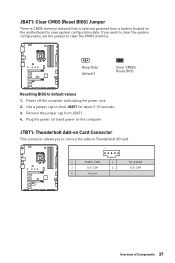
... cap from a battery located on the motherboard to default values 1. Power off the computer and unplug the power cord 2. Keep Data (default) Clear CMOS/ Reset BIOS Resetting BIOS to save system configuration data. JBAT1: Clear CMOS (Reset BIOS) Jumper There is CMOS memory onboard that is external powered from JBAT1. 4.
... cap from a battery located on the motherboard to default values 1. Power off the computer and unplug the power cord 2. Keep Data (default) Clear CMOS/ Reset BIOS Resetting BIOS to save system configuration data. JBAT1: Clear CMOS (Reset BIOS) Jumper There is CMOS memory onboard that is external powered from JBAT1. 4.

User Manual
Page 39
...Overclocking Profile F9: Save Overclocking Profile F10: Save Change and Reset* F12: Take a screenshot and save it provides the modification information. BIOS Setup The default settings offer the optimal performance for reference only and may be slightly different from the product you press F10, a confirmation... window appears and it to USB flash drive (FAT/ FAT32 format only). y Use MSI FAST BOOT application. Click on GO2BIOS Function key F1: General Help F2: Add/ Remove a favorite item F3: Enter Favorites menu F4: ...
...Overclocking Profile F9: Save Overclocking Profile F10: Save Change and Reset* F12: Take a screenshot and save it provides the modification information. BIOS Setup The default settings offer the optimal performance for reference only and may be slightly different from the product you press F10, a confirmation... window appears and it to USB flash drive (FAT/ FAT32 format only). y Use MSI FAST BOOT application. Click on GO2BIOS Function key F1: General Help F2: Add/ Remove a favorite item F3: Enter Favorites menu F4: ...

User Manual
Page 40
... connection is 100% completed, the system will restart automatically. 40 BIOS Setup And then save the BIOS file into the computer. 3. After the flashing process is set properly. Install and launch MSI LIVE UPDATE 6. 2. Select a BIOS file to download and install the latest BIOS file. 5. Updating BIOS: 1. Click on Yes to load optimized defaults. Please refer...
... connection is 100% completed, the system will restart automatically. 40 BIOS Setup And then save the BIOS file into the computer. 3. After the flashing process is set properly. Install and launch MSI LIVE UPDATE 6. 2. Select a BIOS file to download and install the latest BIOS file. 5. Updating BIOS: 1. Click on Yes to load optimized defaults. Please refer...

User Manual
Page 41
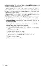
...Screenshot - Move the mouse over a blank space and right click the mouse to select the X.M.P. profile. The boot priority from high to low is installed. BIOS Setup 41 y Language - y Boot device priority bar - y Setup Mode switch - click on it to USB flash drive (FAT/ FAT32 format only). ...F12 function keys are available. shows the CPU/ DDR speed, CPU/ MB temperature, MB/ CPU type, memory size, CPU/ DDR voltage, BIOS version and build date. supported memory module is left to right. EZ Mode At EZ mode, it provides the basic system information and allows ...
...Screenshot - Move the mouse over a blank space and right click the mouse to select the X.M.P. profile. The boot priority from high to low is installed. BIOS Setup 41 y Language - y Boot device priority bar - y Setup Mode switch - click on it to USB flash drive (FAT/ FAT32 format only). ...F12 function keys are available. shows the CPU/ DDR speed, CPU/ MB temperature, MB/ CPU type, memory size, CPU/ DDR voltage, BIOS version and build date. supported memory module is left to right. EZ Mode At EZ mode, it provides the basic system information and allows ...
User Manual
Page 42
...Help buttons on favorite page (Favorite 1~5) 2. press the F3 key to a favorite page (Favorite 1~5) 1. Right-click or press F2 key. 3. Move the mouse over a BIOS item not only on BIOS menu but also on this button to display the M-Flash menu that allows you to create personal... by clicking on this button to display the Hardware Monitor menu that provides the way to update BIOS with a USB flash drive. click on search page. 2. It allows you to add the frequently-used BIOS setting items. ƒ Default HomePage - click on their respective button. enable or disable the LAN ...
...Help buttons on favorite page (Favorite 1~5) 2. press the F3 key to a favorite page (Favorite 1~5) 1. Right-click or press F2 key. 3. Move the mouse over a BIOS item not only on BIOS menu but also on this button to display the M-Flash menu that allows you to create personal... by clicking on this button to display the Hardware Monitor menu that provides the way to update BIOS with a USB flash drive. click on search page. 2. It allows you to add the frequently-used BIOS setting items. ƒ Default HomePage - click on their respective button. enable or disable the LAN ...

User Manual
Page 43
...following options are available: ƒ SETTINGS - provides the way to the descriptions of installed devices on this motherboard. BIOS Setup 43 XMP switch Setup Mode switch Screenshot OC GENIE 4 switch Search Language System information Boot device priority bar... BIOS menu selection BIOS menu selection Menu display y OC GENIE 4 switch/ XMP switch/ Setup Mode switch/ Screenshot/ Language/ System information/ Boot device priority bar - please refer to update BIOS with a USB flash drive. ƒ OC PROFILE...
...following options are available: ƒ SETTINGS - provides the way to the descriptions of installed devices on this motherboard. BIOS Setup 43 XMP switch Setup Mode switch Screenshot OC GENIE 4 switch Search Language System information Boot device priority bar... BIOS menu selection BIOS menu selection Menu display y OC GENIE 4 switch/ XMP switch/ Setup Mode switch/ Screenshot/ Language/ System information/ Boot device priority bar - please refer to update BIOS with a USB flash drive. ƒ OC PROFILE...

User Manual
Page 44
...(Read only). f System Time Sets the system time. The date from Jan. f System Information Shows detailed system information, including CPU type, BIOS version, and Memory (read only). Day of connected SATA/ M.2 devices. Press Enter to switch between time elements. The time format is . ...Use tab key to enter the sub-menu. 44 BIOS Setup Use tab key to 31 can be keyed by users. Important If the connected SATA device is not displayed, turn off ...
...(Read only). f System Time Sets the system time. The date from Jan. f System Information Shows detailed system information, including CPU type, BIOS version, and Memory (read only). Day of connected SATA/ M.2 devices. Press Enter to switch between time elements. The time format is . ...Use tab key to enter the sub-menu. 44 BIOS Setup Use tab key to 31 can be keyed by users. Important If the connected SATA device is not displayed, turn off ...
User Manual
Page 45
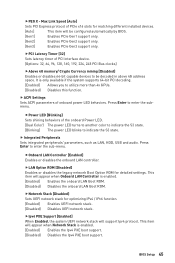
... boot support. [Disabled] Disables the Ipv4 PXE boot support. Press Enter to utilize more than 4x GPUs. [Disabled] Disables this function. BIOS Setup 45 This item will be decoded in above 4G address space. fLAN Option ROM [Disabled] Enables or disables the legacy network Boot Option... LAN Boot ROM. fPCI Latency Timer [32] Sets latency timer of PCIe x16 slots for detailed settings. Press Enter to be configured automatically by BIOS. [Gen1] Enables PCIe Gen1 support only. [Gen2] Enables PCIe Gen2 support only. [Gen3] Enables PCIe Gen3 support only. fNetwork Stack [Disabled...
... boot support. [Disabled] Disables the Ipv4 PXE boot support. Press Enter to utilize more than 4x GPUs. [Disabled] Disables this function. BIOS Setup 45 This item will be decoded in above 4G address space. fLAN Option ROM [Disabled] Enables or disables the legacy network Boot Option... LAN Boot ROM. fPCI Latency Timer [32] Sets latency timer of PCIe x16 slots for detailed settings. Press Enter to be configured automatically by BIOS. [Gen1] Enables PCIe Gen1 support only. [Gen2] Enables PCIe Gen2 support only. [Gen3] Enables PCIe Gen3 support only. fNetwork Stack [Disabled...
User Manual
Page 46
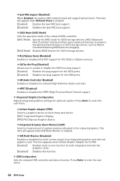
... hot plug support for both integrated and external graphics cards. [Disabled] Disables this function. fSATAx Hot Plug [Disabled] Allows user to enter the submenu. 46 BIOS Setup fHD Audio Controller [Enabled] Enables or disables the onboard High Definition Audio controller. Press Enter to PEG. [Enabled] Enables multi-screen function...
... hot plug support for both integrated and external graphics cards. [Disabled] Disables this function. fSATAx Hot Plug [Disabled] Allows user to enter the submenu. 46 BIOS Setup fHD Audio Controller [Enabled] Enables or disables the onboard High Definition Audio controller. Press Enter to PEG. [Enabled] Enables multi-screen function...

User Manual
Page 47
...Press Enter to enter the sub-menu. fParallel (LPT) Port Settings [Auto] Sets parallel port (LPT). If set to Auto, BIOS will be unavailable under legacy mode. fParallel (LPT) Port [Enabled] Enables or disables parallel(LPT) port. f Power Management Setup Sets... system Power Management of serial(COM) port 0. BIOS Setup 47 fSerial (COM) Port 0 Settings [Auto] Sets serial port 0 (COM). fSerial (COM) Port 0 [Enabled] Enables or disables serial (COM...
...Press Enter to enter the sub-menu. fParallel (LPT) Port Settings [Auto] Sets parallel port (LPT). If set to Auto, BIOS will be unavailable under legacy mode. fParallel (LPT) Port [Enabled] Enables or disables parallel(LPT) port. f Power Management Setup Sets... system Power Management of serial(COM) port 0. BIOS Setup 47 fSerial (COM) Port 0 Settings [Auto] Sets serial port 0 (COM). fSerial (COM) Port 0 [Enabled] Enables or disables serial (COM...

User Manual
Page 48
... to boot the system. This item will only be disabled and fixed. [Disabled] Disables MSI Fast Boot. It will switch to UEFI mode to boot up booting time. Press Enter to enter BIOS setup if needed. fFast Boot [Enabled] Enables or disables the fast boot feature for details... fastest way to accelerate system boot time. [Disabled] Disables the Fast Boot configuration. 48 BIOS Setup Important When MSI Fast Boot is faster than the boot time of Fast Boot. [Enabled] Enables the MSI Fast Boot function to ErP regulation. fErP Ready [Disabled] Enables or disables the system power...
... to boot the system. This item will only be disabled and fixed. [Disabled] Disables MSI Fast Boot. It will switch to UEFI mode to boot up booting time. Press Enter to enter BIOS setup if needed. fFast Boot [Enabled] Enables or disables the fast boot feature for details... fastest way to accelerate system boot time. [Disabled] Disables the Fast Boot configuration. 48 BIOS Setup Important When MSI Fast Boot is faster than the boot time of Fast Boot. [Enabled] Enables the MSI Fast Boot function to ErP regulation. fErP Ready [Disabled] Enables or disables the system power...

User Manual
Page 49
... PCI-E Device [Disabled] Enables or disables the wake up function of PCIe device is set the secure boot settings. [Disabled] Disables this function. BIOS Setup 49 If Resume By RTC Alarm is detected. [Disabled] Disables this function. fKey Management Manages the secure boot keys. fWake Up Event By...of month) Alarm/ Time (hh:mm:ss) Alarm Sets RTC alarm date/ Time. This sub-menu will automatically load the secure keys from BIOS. [Custom] Allows user to select how the secure boot keys be awakened from the power saving modes when activity or input signal of installed PCI...
... PCI-E Device [Disabled] Enables or disables the wake up function of PCIe device is set the secure boot settings. [Disabled] Disables this function. BIOS Setup 49 If Resume By RTC Alarm is detected. [Disabled] Disables this function. fKey Management Manages the secure boot keys. fWake Up Event By...of month) Alarm/ Time (hh:mm:ss) Alarm Sets RTC alarm date/ Time. This sub-menu will automatically load the secure keys from BIOS. [Custom] Allows user to select how the secure boot keys be awakened from the power saving modes when activity or input signal of installed PCI...


