Owners Manual
Page 1
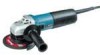
a Angle Grinder 100 mm (4") 100 mm (4") 115 mm (4-112") MODEL 9 5 6 0 C V MODEL 9563CV MODEL 9 5 6 1 C V 115 mm (4-112") 125 m m (5") MODEL 9 5 6 4 C V MODEL 9565CV INSTRUCTION MANUAL DOUBLE INSULATION SPECIFICATIONS 1 I MODEL No load speed (RPM) Overall lenqth I Net weiaht 1 Spindle thread 1 1 1 I 9560CV 2,800 10,5001min 289 m m (11 318") 1 7 k q ( 3 . 7 Ibs) M I 0 x 1 25 I I 1 1 9563CV 2,800 ~ 10,5001min. 2 9 9 mm (11-314") 1.8 ka (4.0 Ibsl M I 0 x 1.25 _ _ _9 5 6 1 C V 2.800 - 10,5001min 289 ...
a Angle Grinder 100 mm (4") 100 mm (4") 115 mm (4-112") MODEL 9 5 6 0 C V MODEL 9563CV MODEL 9 5 6 1 C V 115 mm (4-112") 125 m m (5") MODEL 9 5 6 4 C V MODEL 9565CV INSTRUCTION MANUAL DOUBLE INSULATION SPECIFICATIONS 1 I MODEL No load speed (RPM) Overall lenqth I Net weiaht 1 Spindle thread 1 1 1 I 9560CV 2,800 10,5001min 289 m m (11 318") 1 7 k q ( 3 . 7 Ibs) M I 0 x 1 25 I I 1 1 9563CV 2,800 ~ 10,5001min. 2 9 9 mm (11-314") 1.8 ka (4.0 Ibsl M I 0 x 1.25 _ _ _9 5 6 1 C V 2.800 - 10,5001min 289 ...
Owners Manual
Page 2
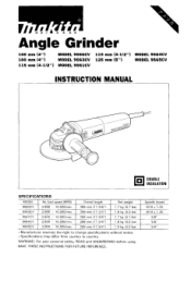
... instructions. Distractions can be caught in a polarized outlet only one blade is grounded. 6. Electrical Safety 4. When operating a power tool outside, use common sense when operating a power tool. Do not wear loose clothing or jewelry. Keep your hair, clothing, and gloves away from moving parts. Keep your body is wider than the other.) This plug will increase the risk of electric shock. Do not change...
... instructions. Distractions can be caught in a polarized outlet only one blade is grounded. 6. Electrical Safety 4. When operating a power tool outside, use common sense when operating a power tool. Do not wear loose clothing or jewelry. Keep your hair, clothing, and gloves away from moving parts. Keep your body is wider than the other.) This plug will increase the risk of electric shock. Do not change...
Owners Manual
Page 3
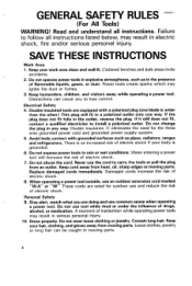
... starting . Use only accessories that have the tool serviced before plugging in tools that are caused by hand or against your application. Always wear eye protection. Do not use only identical replacement parts. Such preventive safety measures reduce the risk of the tool in the Maintenance section of parts, and any adjustments, changing accessories, or storing the tool. Maintain tools w i t h care. Tool Use and Care 15. Use of unauthorized parts or failure t o follow Maintenance Instructions...
... starting . Use only accessories that have the tool serviced before plugging in tools that are caused by hand or against your application. Always wear eye protection. Do not use only identical replacement parts. Such preventive safety measures reduce the risk of the tool in the Maintenance section of parts, and any adjustments, changing accessories, or storing the tool. Maintain tools w i t h care. Tool Use and Care 15. Use of unauthorized parts or failure t o follow Maintenance Instructions...
Owners Manual
Page 4
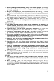
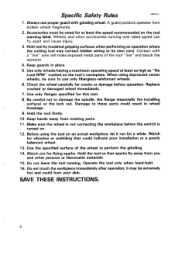
... an operation where the cutting tool may be sure t o use proper guard with a "live" wire will make exposed metal parts of the wheel t o perform the grinding. 14. A guard protects operator from broken wheel fragments. 2. Be careful not t o damage the spindle, the flange (especially the installing surface) or the lock nut. it run for a while. Use only flanges specified for at least as high as "No Load RPM...
... an operation where the cutting tool may be sure t o use proper guard with a "live" wire will make exposed metal parts of the wheel t o perform the grinding. 14. A guard protects operator from broken wheel fragments. 2. Be careful not t o damage the spindle, the flange (especially the installing surface) or the lock nut. it run for a while. Use only flanges specified for at least as high as "No Load RPM...
Owners Manual
Page 5
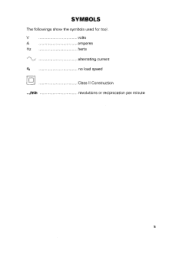
v volts A amperes Hz herts alternating current b no load speed H Class II Construction .../min revolutions or reciprocation per minute 5 SYMBOLS The followings show the symbols used for tool.
v volts A amperes Hz herts alternating current b no load speed H Class II Construction .../min revolutions or reciprocation per minute 5 SYMBOLS The followings show the symbols used for tool.
Owners Manual
Page 6
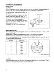
... direction of the switch lever is locked on the dial and the approximate rotating speed. To start the tool, slide the switch lever to the "OFF" position when the side of number 1 . Depressingthe rear of number 5. FUNCTIONAL DESCRIPTION Switch action CAUTION: Before plugging in the tool, always check to see that the switch actuates properly and returns to "I" position. Switch lever Speed adjusting dial The rotating speed can be changed by turning...
... direction of the switch lever is locked on the dial and the approximate rotating speed. To start the tool, slide the switch lever to the "OFF" position when the side of number 1 . Depressingthe rear of number 5. FUNCTIONAL DESCRIPTION Switch action CAUTION: Before plugging in the tool, always check to see that the switch actuates properly and returns to "I" position. Switch lever Speed adjusting dial The rotating speed can be changed by turning...
Owners Manual
Page 7
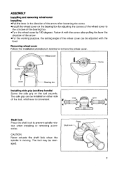
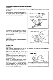
... lever the direction of the arrow. Shaft lock Press the shaft lock to remove the wheel cover Installing side grip (auxiliary handle) Screw the side grip on either side of the tool, whichever is moving. The side grip can be damaged. ASSEMBLY Installing and removing wheel cover Installing Pull the lever in reverse to prevent spindle rotation when installing or removing accessories. The tool may be adjusted with the screw after loosening the screw. Install...
... lever the direction of the arrow. Shaft lock Press the shaft lock to remove the wheel cover Installing side grip (auxiliary handle) Screw the side grip on either side of the tool, whichever is moving. The side grip can be damaged. ASSEMBLY Installing and removing wheel cover Installing Pull the lever in reverse to prevent spindle rotation when installing or removing accessories. The tool may be adjusted with the screw after loosening the screw. Install...
Owners Manual
Page 8
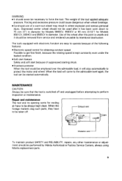
... wheel, do not work the grinder in both A and B direction. 8 WARNING: Only actuate the shaft lock when the spindle is switched off and unplugged before putting the tool down. Mount the inner flange onto the spindle. Hold the tool firmly. In general, keep the edge of the wheel or disc at an angle of the wheel has been rounded off by use the lock nut wrench and securely tighten clockwise. Turn...
... wheel, do not work the grinder in both A and B direction. 8 WARNING: Only actuate the shaft lock when the spindle is switched off and unplugged before putting the tool down. Mount the inner flange onto the spindle. Hold the tool firmly. In general, keep the edge of the wheel or disc at an angle of the wheel has been rounded off by use the lock nut wrench and securely tighten clockwise. Turn...
Owners Manual
Page 9
... product SAFETY and RELIABILITY, repairs, any other maintenance or adjustment should be removed from service and rendered unusable by Makita Authorized or Factory Service Centers, always using Makita replacement parts. 9 Depressed center wheel should never be necessary to perform inspection or maintenance. Soft start feature Safety and soft start because of a worn-out wheel may result in diameter. they have to the admissiblelevel again, the tool can be started automaticallv...
... product SAFETY and RELIABILITY, repairs, any other maintenance or adjustment should be removed from service and rendered unusable by Makita Authorized or Factory Service Centers, always using Makita replacement parts. 9 Depressed center wheel should never be necessary to perform inspection or maintenance. Soft start feature Safety and soft start because of a worn-out wheel may result in diameter. they have to the admissiblelevel again, the tool can be started automaticallv...
Owners Manual
Page 10
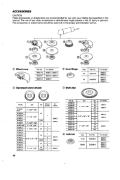
... your Makita tool specified in the proper and intended manner. @ Wheelcover I PanNo. ACCESSORIES CAUTION: These accessories or attachments are recommendedfor use of any other accessories or attachments might present a risk of injury to persons. For Model @ Depressed center wheels Q Inner flange I I Size Part No. M ) - 80 9561CV 9564cv 100 - 40 7 - 60 95650' 100 @ Locknut I I Size P a r t ~ o . The accessories or attachments should be used only in this manual...
... your Makita tool specified in the proper and intended manner. @ Wheelcover I PanNo. ACCESSORIES CAUTION: These accessories or attachments are recommendedfor use of any other accessories or attachments might present a risk of injury to persons. For Model @ Depressed center wheels Q Inner flange I I Size Part No. M ) - 80 9561CV 9564cv 100 - 40 7 - 60 95650' 100 @ Locknut I I Size P a r t ~ o . The accessories or attachments should be used only in this manual...
Owners Manual
Page 11
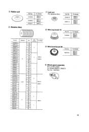
... discs 743036-3 743015-1 9565CV @ Wire cup brush 75 Part No I Diameter 74203603 Per pkg For Model @ Wire bevel brush 85 9565CV 9565CV 9560CV 4' 9563CV 742087-0 7420400 I 794105-A-5 794105-A-5 1 - 794106A-5 794 107-A-5 4-1/2'' 794104-8 8 Wheel guard assembly (For cut-off wheel) For Model 9560CV. 9563CV Part No. 192476-6 5 3561CV 3564CV 794107-8 794108-8 142072-A-5 742073-A-5 742074-A-5 742075-A-5 742076A-5 742072-8 742073-8 742074-8 742075-0 7420768 - 80 120 24 - 30...
... discs 743036-3 743015-1 9565CV @ Wire cup brush 75 Part No I Diameter 74203603 Per pkg For Model @ Wire bevel brush 85 9565CV 9565CV 9560CV 4' 9563CV 742087-0 7420400 I 794105-A-5 794105-A-5 1 - 794106A-5 794 107-A-5 4-1/2'' 794104-8 8 Wheel guard assembly (For cut-off wheel) For Model 9560CV. 9563CV Part No. 192476-6 5 3561CV 3564CV 794107-8 794108-8 142072-A-5 742073-A-5 742074-A-5 742075-A-5 742076A-5 742072-8 742073-8 742074-8 742075-0 7420768 - 80 120 24 - 30...
Owners Manual
Page 12
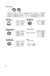
For Model I 743212-A 9561CV 9564CV 9565CV Stringer Bead Twist Wire brush wheel 743213-E 9565CV Full Cable Twist Wire brush wheel I Part No. For Model Lock nut wrench 0 I Part No. @ Cut-off wheel Pan No. For Model 9560cv 9563CV Knot-Type Wire cup brush Knotted-Twist Wire cup brush 9564CV I IV 12 Size Grit 724104-110 4" x 3/32" x 5"' 36 724107-510 4" x 5/64" x 5B" 46 Wheels per pkg. 10 10 For use For masonry and concrete. ForModel 9561CV 9565CV Grip Part No. 152490-4 I Pan No. For steel and cast iron.
For Model I 743212-A 9561CV 9564CV 9565CV Stringer Bead Twist Wire brush wheel 743213-E 9565CV Full Cable Twist Wire brush wheel I Part No. For Model Lock nut wrench 0 I Part No. @ Cut-off wheel Pan No. For Model 9560cv 9563CV Knot-Type Wire cup brush Knotted-Twist Wire cup brush 9564CV I IV 12 Size Grit 724104-110 4" x 3/32" x 5"' 36 724107-510 4" x 5/64" x 5B" 46 Wheels per pkg. 10 10 For use For masonry and concrete. ForModel 9561CV 9565CV Grip Part No. 152490-4 I Pan No. For steel and cast iron.
Owners Manual
Page 14
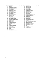
... 30 SWITCH LEVER 31 COMPRESSION SPRING 4 NO USED 1 1 1 1 1 1 1 1 I 1 1 1 1 1 1 1 1 1 1 1 2 2 2 1 2 1 1 1 1 1 1 ITEM NO DESCRIPTION 32 BRUSH HOLDER 33 MOTOR HOUSING 34 MAKITA LABEL 35 SWITCH KNOB 36 CORD GUARD 8 37 POWER SUPPLY CORD 38 REAR COVER 39 TAPPING SCREW 4x18 40 INDICATION LABEL 41 CONTROLLER 42 A C CARBON BRUSH CB-318 43 BRUSH HOLDER 44 TAPPING SCREW PT3XlO 45 NAME PLATE 46 LOCK NUT 10-35 41 INNER FLANGE 35 48 WHEEL COVER 49 PAN HEAD SCREW M5XI6 50 SPINDLE 51...
... 30 SWITCH LEVER 31 COMPRESSION SPRING 4 NO USED 1 1 1 1 1 1 1 1 I 1 1 1 1 1 1 1 1 1 1 1 2 2 2 1 2 1 1 1 1 1 1 ITEM NO DESCRIPTION 32 BRUSH HOLDER 33 MOTOR HOUSING 34 MAKITA LABEL 35 SWITCH KNOB 36 CORD GUARD 8 37 POWER SUPPLY CORD 38 REAR COVER 39 TAPPING SCREW 4x18 40 INDICATION LABEL 41 CONTROLLER 42 A C CARBON BRUSH CB-318 43 BRUSH HOLDER 44 TAPPING SCREW PT3XlO 45 NAME PLATE 46 LOCK NUT 10-35 41 INNER FLANGE 35 48 WHEEL COVER 49 PAN HEAD SCREW M5XI6 50 SPINDLE 51...
Owners Manual
Page 15
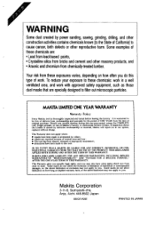
... power sanding, sawing, grinding, drilling, and other construction activities contains chemicals known [to the State of Califomia]to you. Your risk from these chemicals are specially designed to these chemicals: work in a well ventilated area, and work . To reduce your exposure to filter out microscopic particles. Should any trouble develop during this type of Makita's Factory or Authorized Service Centers. MAKITA...
... power sanding, sawing, grinding, drilling, and other construction activities contains chemicals known [to the State of Califomia]to you. Your risk from these chemicals are specially designed to these chemicals: work in a well ventilated area, and work . To reduce your exposure to filter out microscopic particles. Should any trouble develop during this type of Makita's Factory or Authorized Service Centers. MAKITA...
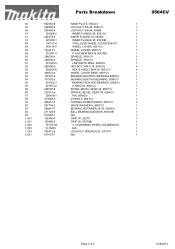
Parts Breakdown
Page 2
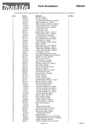
..., 9563CV ARMATURE ASSEMBLY, 9564CV ARMATURE ASSEMBLY, 9565CV INSULATION WASHER, GD0800C F. MOTOR HOUSING CPL.,9566CV MOTOR HOUSING CPL,9564CV MOTOR HOUSING CPL., 9564CV MOTOR HOUSING CPL., 9564CV MOTOR HOUSING, 9563CV MAKITA LABEL, 4331DWD SWITCH KNOB, 9560CV SWITCH KNOB, BO6040 CORD GUARD 10, 9564CV CORD (2X16X8;SJ), 5007NBA REAR COVER, 9564CV N/A REAR COVER, BO6040 TAPPING SCREW 4X18, 4323K INDICATION LABEL, 9561CV INDICATION LABEL, 9564CV CONTROLLER, 9564CV CARBON BRUSH CARBON BRUSH SET CB-318,GD0800C CARBON BRUSH SET CB-318, GD0800C BRUSH HOLDER, 9557NB TAPPING SCREW PT3X10, GD0800C Page...
..., 9563CV ARMATURE ASSEMBLY, 9564CV ARMATURE ASSEMBLY, 9565CV INSULATION WASHER, GD0800C F. MOTOR HOUSING CPL.,9566CV MOTOR HOUSING CPL,9564CV MOTOR HOUSING CPL., 9564CV MOTOR HOUSING CPL., 9564CV MOTOR HOUSING, 9563CV MAKITA LABEL, 4331DWD SWITCH KNOB, 9560CV SWITCH KNOB, BO6040 CORD GUARD 10, 9564CV CORD (2X16X8;SJ), 5007NBA REAR COVER, 9564CV N/A REAR COVER, BO6040 TAPPING SCREW 4X18, 4323K INDICATION LABEL, 9561CV INDICATION LABEL, 9564CV CONTROLLER, 9564CV CARBON BRUSH CARBON BRUSH SET CB-318,GD0800C CARBON BRUSH SET CB-318, GD0800C BRUSH HOLDER, 9557NB TAPPING SCREW PT3X10, GD0800C Page...
Parts Breakdown
Page 3
...-4 153489-2 741423-B D-18459 782412-6 810157-7 Parts Breakdown NAME PLATE, 9564CV LOCK NUT 5/8-45, 9561CV LOCK NUT 5/8-45, 9005B INNER FLANGE 45, 9561CV INNER FLANGE 45, 9005B INNER FLANGE 45, 9554NB TOOL LESS WHEEL COVER,9564CV WHEEL COVER, 9561CV WHEEL COVER, 9561CV P.H.SCREW M5X16,9523NB SPINDLE, 9561CV SPINDLE, 9561CV LABYRINTH RING, 9564CV HEX BOLT M4 X 16, 9560CV HEX.S.H.BOLT M4X16, 9561CV WHEEL COVER BASE, 9561CV BEARING BOX/WITH BEARING,9560CV...
...-4 153489-2 741423-B D-18459 782412-6 810157-7 Parts Breakdown NAME PLATE, 9564CV LOCK NUT 5/8-45, 9561CV LOCK NUT 5/8-45, 9005B INNER FLANGE 45, 9561CV INNER FLANGE 45, 9005B INNER FLANGE 45, 9554NB TOOL LESS WHEEL COVER,9564CV WHEEL COVER, 9561CV WHEEL COVER, 9561CV P.H.SCREW M5X16,9523NB SPINDLE, 9561CV SPINDLE, 9561CV LABYRINTH RING, 9564CV HEX BOLT M4 X 16, 9560CV HEX.S.H.BOLT M4X16, 9561CV WHEEL COVER BASE, 9561CV BEARING BOX/WITH BEARING,9560CV...


