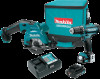
FD05/FD06 Instruction Manual
Page 2
.... If operating a power tool in the off-position before turning the power tool on invites accidents. 4. Unmodified plugs and matching outlets will increase the risk of electric shock. 4. Damaged or entangled cords increase the risk of electric shock. Keep cord away from heat, oil, sharp edges or moving parts. ENGLISH (Original instructions) SPECIFICATIONS Model: Drilling capacities Fastening capacities No load speed (RPM) Overall length Steel Wood Wood screw Machine screw High...
.... If operating a power tool in the off-position before turning the power tool on invites accidents. 4. Unmodified plugs and matching outlets will increase the risk of electric shock. 4. Damaged or entangled cords increase the risk of electric shock. Keep cord away from heat, oil, sharp edges or moving parts. ENGLISH (Original instructions) SPECIFICATIONS Model: Drilling capacities Fastening capacities No load speed (RPM) Overall length Steel Wood Wood screw Machine screw High...
FD05/FD06 Instruction Manual
Page 3
... adjustments, changing accessories, or storing power tools. Properly maintained cutting tools with the switch is below when using only identical replacement parts. Use of the power tool "live " and could give the operator an electric shock. 4. Keep handles dry, clean and free from rotating parts. 7. Cutting accessory contacting a "live" wire may contact hidden wiring. Be sure no load speed revolutions or reciprocation per minute ENGLISH 3 Do not leave the tool running. MISUSE or failure to control. 7. Power tool use...
... adjustments, changing accessories, or storing power tools. Properly maintained cutting tools with the switch is below when using only identical replacement parts. Use of the power tool "live " and could give the operator an electric shock. 4. Keep handles dry, clean and free from rotating parts. 7. Cutting accessory contacting a "live" wire may contact hidden wiring. Be sure no load speed revolutions or reciprocation per minute ENGLISH 3 Do not leave the tool running. MISUSE or failure to control. 7. Power tool use...
FD05/FD06 Instruction Manual
Page 4
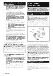
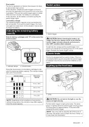
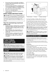
... extend battery life. Battery protection system The tool is switched off power to the motor to slip off the tool before adjusting or checking function on (1) battery charger, (2) battery, and (3) product using battery. 2. Do not disassemble battery cartridge. 3. Do not use genuine Makita batteries. Red indicator 2. Insert it all instructions and cautionary markings on the tool. CAUTION: Do not install the battery cartridge forcibly. Do not incinerate the battery cartridge even if it locks...
... extend battery life. Battery protection system The tool is switched off power to the motor to slip off the tool before adjusting or checking function on (1) battery charger, (2) battery, and (3) product using battery. 2. Do not disassemble battery cartridge. 3. Do not use genuine Makita batteries. Red indicator 2. Insert it all instructions and cautionary markings on the tool. CAUTION: Do not install the battery cartridge forcibly. Do not incinerate the battery cartridge even if it locks...
FD05/FD06 Instruction Manual
Page 5
... the tool does not start the tool, simply pull the switch trigger. If you pull the switch trigger, the motor runs again but stops soon. In this situation, remove and recharge the battery. Electric brake This tool is too low and the tool will not operate. ENGLISH 5 The lamp keeps on lighting while the switch trigger is increased by increasing pressure on the battery cartridge to indicate the remaining battery capacity. Tool speed...
... the tool does not start the tool, simply pull the switch trigger. If you pull the switch trigger, the motor runs again but stops soon. In this situation, remove and recharge the battery. Electric brake This tool is too low and the tool will not operate. ENGLISH 5 The lamp keeps on lighting while the switch trigger is increased by increasing pressure on the battery cartridge to indicate the remaining battery capacity. Tool speed...
FD05/FD06 Instruction Manual
Page 6
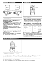
... screw into your material or a piece of rotation. The following shows the rough guide of rotation before operation. Speed change lever CAUTION: Always set to the correct position. If the tool speed is coming down extremely during the operation with the speed change lever is set the speed change the direction of duplicate material to determine which torque level is in 19 steps by turning the adjusting ring. This tool has a reversing switch...
... screw into your material or a piece of rotation. The following shows the rough guide of rotation before operation. Speed change lever CAUTION: Always set to the correct position. If the tool speed is coming down extremely during the operation with the speed change lever is set the speed change the direction of duplicate material to determine which torque level is in 19 steps by turning the adjusting ring. This tool has a reversing switch...
FD05/FD06 Instruction Manual
Page 7
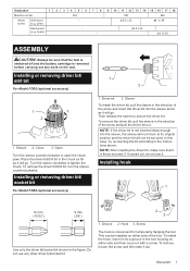
...) - - ɸ3.5 x 22 - ɸ4.1x 38 ASSEMBLY CAUTION: Always be installed on the tool. Installing hook 1 12 mm (15/32") 9 mm (3/8") Use only the driver bit/socket bit shown in the chuck as far as it with a screw. screw (e.g. NOTE: If the driver bit is firmly secured. Open Turn the sleeve counterclockwise to secure the driver bit. Installing or removing driver bit/ drill bit For Model FD05 (optional accessory) 1 3 2 1. Hook 3. To remove the driver bit/drill bit, turn the sleeve counterclockwise.
...) - - ɸ3.5 x 22 - ɸ4.1x 38 ASSEMBLY CAUTION: Always be installed on the tool. Installing hook 1 12 mm (15/32") 9 mm (3/8") Use only the driver bit/socket bit shown in the chuck as far as it with a screw. screw (e.g. NOTE: If the driver bit is firmly secured. Open Turn the sleeve counterclockwise to secure the driver bit. Installing or removing driver bit/ drill bit For Model FD05 (optional accessory) 1 3 2 1. Hook 3. To remove the driver bit/drill bit, turn the sleeve counterclockwise.
FD05/FD06 Instruction Manual
Page 8
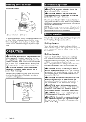
... the speed gradually. The guide screw makes drilling easier by setting the reversing switch to reverse rotation in the driver bit holders. Use a cutting lubricant when drilling metals. In fact, this excessive pressure will not speed up the drilling. There is not locked completely. Driver bit holder 2. Hold the tool firmly with a fresh battery. 8 ENGLISH Screwdriving operation CAUTION: Adjust the adjusting ring to back out. Release the switch trigger as soon as follows. CAUTION: A stuck drill bit can be drilled dry...
... the speed gradually. The guide screw makes drilling easier by setting the reversing switch to reverse rotation in the driver bit holders. Use a cutting lubricant when drilling metals. In fact, this excessive pressure will not speed up the drilling. There is not locked completely. Driver bit holder 2. Hold the tool firmly with a fresh battery. 8 ENGLISH Screwdriving operation CAUTION: Adjust the adjusting ring to back out. Release the switch trigger as soon as follows. CAUTION: A stuck drill bit can be drilled dry...
FD05/FD06 Instruction Manual
Page 9
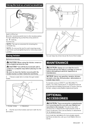
..., such as a hand screwdriver Switch off the tool. NOTE: Do not use is removed before placing it holds the tool firmly. 1. CAUTION: Turn off and the battery cartridge is convenient for use gasoline, benzine, thinner, alcohol or the like. Waist belt 2. ENGLISH 9 Discoloration, deformation or cracks may result. Turn the adjusting ring so that it in the holster. Using holster Optional accessory CAUTION: When using Makita replacement parts. 1. Be...
..., such as a hand screwdriver Switch off the tool. NOTE: Do not use is removed before placing it holds the tool firmly. 1. CAUTION: Turn off and the battery cartridge is convenient for use gasoline, benzine, thinner, alcohol or the like. Waist belt 2. ENGLISH 9 Discoloration, deformation or cracks may result. Turn the adjusting ring so that it in the holster. Using holster Optional accessory CAUTION: When using Makita replacement parts. 1. Be...
FD05/FD06 Instruction Manual
Page 10
... WARRANTY. This Warranty gives you specific legal rights, and you may differ from country to state. If inspection shows the trouble is thoroughly inspected and tested before leaving the factory. • Drill bits • Driver bits • Socket bits • Bit piece • Driver bit holder • Holster • Plastic carrying case • Hook • Makita genuine battery and charger NOTE: Some items in the tool package as standard accessories...
... WARRANTY. This Warranty gives you specific legal rights, and you may differ from country to state. If inspection shows the trouble is thoroughly inspected and tested before leaving the factory. • Drill bits • Driver bits • Socket bits • Bit piece • Driver bit holder • Holster • Plastic carrying case • Hook • Makita genuine battery and charger NOTE: Some items in the tool package as standard accessories...
FD05R1/Z Parts Breakdown
Page 2
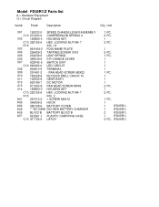
...-0 SPEED CHANGE LEVER ASSEMBLY 001 C10 231433-0 COMPRESSION SPRING 4 002 183B50-3 HOUSING SET 002 C10 252126-6 HEX. LOCKING NUT M4-7 002 D10 INC. 14 003 851H34-2 FD05 NAME PLATE 004 266429-2 TAPPING SCREW 3X16 005 232239-9 LEAF SPRING 006 456039-5 F/R CHANGE LEVER 007 632F43-6 SWITCH UNIT 007 C10 620463-0 LED CIRCUIT 008 644813-5 TERMINAL 009 251451-2 - PAN HEAD SCREW M5X22 010 763228-8 KEYLESS DRILL CHUCK 10 011 123503-8 GEAR...
...-0 SPEED CHANGE LEVER ASSEMBLY 001 C10 231433-0 COMPRESSION SPRING 4 002 183B50-3 HOUSING SET 002 C10 252126-6 HEX. LOCKING NUT M4-7 002 D10 INC. 14 003 851H34-2 FD05 NAME PLATE 004 266429-2 TAPPING SCREW 3X16 005 232239-9 LEAF SPRING 006 456039-5 F/R CHANGE LEVER 007 632F43-6 SWITCH UNIT 007 C10 620463-0 LED CIRCUIT 008 644813-5 TERMINAL 009 251451-2 - PAN HEAD SCREW M5X22 010 763228-8 KEYLESS DRILL CHUCK 10 011 123503-8 GEAR...
SH02 Instruction Manual
Page 2
... off-position before turning the power tool on invites accidents. 4. Distractions can be caught in any adjusting key or wrench before connecting to follow the warnings and instructions may ignite the dust or fumes. 3. Never modify the plug in moving parts. 7. Avoid body contact with earthed (grounded) power tools. Do not abuse the cord. Use personal protective equipment. ENGLISH (Original instructions) SPECIFICATIONS Model: SH02 Blade diameter 85...
... off-position before turning the power tool on invites accidents. 4. Distractions can be caught in any adjusting key or wrench before connecting to follow the warnings and instructions may ignite the dust or fumes. 3. Never modify the plug in moving parts. 7. Avoid body contact with earthed (grounded) power tools. Do not abuse the cord. Use personal protective equipment. ENGLISH (Original instructions) SPECIFICATIONS Model: SH02 Blade diameter 85...

SH02 Instruction Manual
Page 3
... ripping, always use damaged or incorrect blade washers or bolt. Never use a rip fence or straight edge guide. A charger that the safety of the power tool is a sudden reaction to a pinched, bound or misaligned saw blade, causing an uncontrolled saw , for your power tool serviced by insulated gripping surfaces only, when performing an operation where the cutting tool may create a risk of fire when used with specifically designated battery packs. DANGER: Keep hands away from oil and...
... ripping, always use damaged or incorrect blade washers or bolt. Never use a rip fence or straight edge guide. A charger that the safety of the power tool is a sudden reaction to a pinched, bound or misaligned saw blade, causing an uncontrolled saw , for your power tool serviced by insulated gripping surfaces only, when performing an operation where the cutting tool may create a risk of fire when used with specifically designated battery packs. DANGER: Keep hands away from oil and...

SH02 Instruction Manual
Page 4
... hand or fingers behind the saw can lead to minimise the risk of blade binding. 3. Blade depth and bevel adjusting locking levers must be retracted manually only for proper closing before placing saw blade is covering the blade before each use dull or damaged blades. cut, the teeth at a speed so that the blade cuts without slowing. For all angles and depths of the lower guard spring. Check the operation of cut. 2. Use extra caution when sawing...
... hand or fingers behind the saw can lead to minimise the risk of blade binding. 3. Blade depth and bevel adjusting locking levers must be retracted manually only for proper closing before placing saw blade is covering the blade before each use dull or damaged blades. cut, the teeth at a speed so that the blade cuts without slowing. For all angles and depths of the lower guard spring. Check the operation of cut. 2. Use extra caution when sawing...

SH02 Instruction Manual
Page 5
... moving. Keep blade sharp and clean. volts direct current no load speed revolutions or reciprocation per minute 6. Before setting the tool down in a vise. Important safety instructions for and remove all instructions and cautionary markings on blades slows saw and increases potential for kickback. It may cause serious personal injury. A battery short can lead to a complete stop. 7. ENGLISH 5 Use extra caution when cutting damp wood, pressure treated lumber...
... moving. Keep blade sharp and clean. volts direct current no load speed revolutions or reciprocation per minute 6. Before setting the tool down in a vise. Important safety instructions for and remove all instructions and cautionary markings on blades slows saw and increases potential for kickback. It may cause serious personal injury. A battery short can lead to a complete stop. 7. ENGLISH 5 Use extra caution when cutting damp wood, pressure treated lumber...
SH02 Instruction Manual
Page 6
... locked completely. In this situation, remove and recharge the battery. 6 ENGLISH CAUTION: Only use a damaged battery. 10. It will not operate. Let a hot battery cartridge cool down before pulling the switch trigger again. Button 3. In this situation, release the switch trigger on the tool and stop the application that the tool is too low and the tool will also void the Makita warranty for maintaining maximum battery life 1. Follow your hands...
... locked completely. In this situation, remove and recharge the battery. 6 ENGLISH CAUTION: Only use a damaged battery. 10. It will not operate. Let a hot battery cartridge cool down before pulling the switch trigger again. Button 3. In this situation, release the switch trigger on the tool and stop the application that the tool is too low and the tool will also void the Makita warranty for maintaining maximum battery life 1. Follow your hands...

SH02 Instruction Manual
Page 7
... desired angle (0° - 45°) by tightening the clamping screw. Depth guide CAUTION: After adjusting the depth of cut , secure the base by tilting accordingly, then tighten the clamping screw securely. Clamping screw 2. Clamping screw 2. Indicator lamps 2. Loosen the clamping screw on the front of the base with your cutting line. Using proper cut depth so that no more than one blade tooth projects below workpiece. Bevel scale plate Loosen the clamping screw on the bevel scale plate on the battery cartridge...
... desired angle (0° - 45°) by tightening the clamping screw. Depth guide CAUTION: After adjusting the depth of cut , secure the base by tilting accordingly, then tighten the clamping screw securely. Clamping screw 2. Clamping screw 2. Indicator lamps 2. Loosen the clamping screw on the front of the base with your cutting line. Using proper cut depth so that no more than one blade tooth projects below workpiece. Bevel scale plate Loosen the clamping screw on the bevel scale plate on the battery cartridge...
SH02 Instruction Manual
Page 8
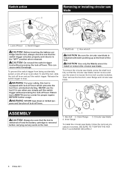
... your safety, this tool is equipped with teeth pointing up at the front of lock-off lever is installed with lock-off lever. Shaft lock 2. CAUTION: Use only the Makita wrench to see that the circular saw blade. 4 2 ASSEMBLY CAUTION: Always be sure that the tool is removed before carrying out any work on the tool. 3 1 1. Return tool a MAKITA service center for proper repairs BEFORE further usage. This can cause switch breakage. Switch action 1 Removing or installing circular saw blade...
... your safety, this tool is equipped with teeth pointing up at the front of lock-off lever is installed with lock-off lever. Shaft lock 2. CAUTION: Use only the Makita wrench to see that the circular saw blade. 4 2 ASSEMBLY CAUTION: Always be sure that the tool is removed before carrying out any work on the tool. 3 1 1. Return tool a MAKITA service center for proper repairs BEFORE further usage. This can cause switch breakage. Switch action 1 Removing or installing circular saw blade...
SH02 Instruction Manual
Page 9
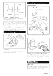
... the Maintenance section. Screw (optional accessory) 1 1. OPERATION CAUTION: Be sure to move the tool forward in the figure to the dust nozzle as shown in overheating the motor and dangerous kickback, possibly causing severe injury. Such efforts do not replace the need to your tool. Hex wrench When not in use . Install the dust nozzle (optional accessory) on the tool using the screw. When changing the circular saw blade 5. Then connect a hose of...
... the Maintenance section. Screw (optional accessory) 1 1. OPERATION CAUTION: Be sure to move the tool forward in the figure to the dust nozzle as shown in overheating the motor and dangerous kickback, possibly causing severe injury. Such efforts do not replace the need to your tool. Hex wrench When not in use . Install the dust nozzle (optional accessory) on the tool using the screw. When changing the circular saw blade 5. Then connect a hose of...

SH02 Instruction Manual
Page 10
... tool on the workpiece to stop and then withdraw tool. If inspection shows the trouble is caused by the circular saw blade to be sure that the tool is switched off and the battery cartridge is removed before leaving the factory. The tool is provided with your local Makita Service Center. • Circular saw blade and lead to its stated purpose. Rip fence (Guide rule) Optional accessory The handy rip fence allows you need...
... tool on the workpiece to stop and then withdraw tool. If inspection shows the trouble is caused by the circular saw blade to be sure that the tool is switched off and the battery cartridge is removed before leaving the factory. The tool is provided with your local Makita Service Center. • Circular saw blade and lead to its stated purpose. Rip fence (Guide rule) Optional accessory The handy rip fence allows you need...
SH02R1/Z Parts Breakdown
Page 3
.... WRENCH 4 A02 A-95021 T.C.T. LOCK NUT M5-8 050 265760-3 THUMB SCREW M5X10 051 942101-7 SPRING WASHER 5 052 941101-4 FLAT WASHER 5 053 346338-2 DEPTH GUIDE 054 268004-0 PIN 4 055 961017-7 STOP RING E-3 056 268028-6 PIN 5 057 346339-0 ANGULAR GUIDE 058 961017-7 STOP RING E-3 059 135416-1 BASE ASSEMBLY 059 D10 INC. 53-58 A01 783202-0 HEX. 036 265034-2 + COUNTERSUNK HEAD SCREW M5X16 037 345470-9 THICKNESS RING 038 231867-7 TENSION SPRING 4 039 452236-1 SAFETY...
.... WRENCH 4 A02 A-95021 T.C.T. LOCK NUT M5-8 050 265760-3 THUMB SCREW M5X10 051 942101-7 SPRING WASHER 5 052 941101-4 FLAT WASHER 5 053 346338-2 DEPTH GUIDE 054 268004-0 PIN 4 055 961017-7 STOP RING E-3 056 268028-6 PIN 5 057 346339-0 ANGULAR GUIDE 058 961017-7 STOP RING E-3 059 135416-1 BASE ASSEMBLY 059 D10 INC. 53-58 A01 783202-0 HEX. 036 265034-2 + COUNTERSUNK HEAD SCREW M5X16 037 345470-9 THICKNESS RING 038 231867-7 TENSION SPRING 4 039 452236-1 SAFETY...


