

Owners Manual
Page 2
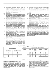
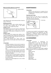
..., oil, sharp edges or moving parts. 11. Electrical Safety 4. Do not change without notice. • Specifications may result in electric shock, fire and/or serious personal injury. Do not expose power tools to install a polarized outlet. Replace damaged cords immediately. Personal Safety 9. A moment of research and development, the specifications herein are rated for the three wire grounded power cord and grounded power supply system. 5. Be sure switch is off before turning...
..., oil, sharp edges or moving parts. 11. Electrical Safety 4. Do not change without notice. • Specifications may result in electric shock, fire and/or serious personal injury. Do not expose power tools to install a polarized outlet. Replace damaged cords immediately. Personal Safety 9. A moment of research and development, the specifications herein are rated for the three wire grounded power cord and grounded power supply system. 5. Be sure switch is off before turning...
Owners Manual
Page 3
... of starting the tool accidentally. 19. Holding the work by insulated gripping surfaces when performing an operation where the cutting tool may contact hidden wiring or its own cord. Check for misalignment or binding of moving parts, breakage of unauthorized parts or failure to follow Maintenance instructions may affect the tool's operation. Many accidents are caused by qualified repair personnel. SERVICE 23. Use of parts, and any adjustments, changing accessories, or...
... of starting the tool accidentally. 19. Holding the work by insulated gripping surfaces when performing an operation where the cutting tool may contact hidden wiring or its own cord. Check for misalignment or binding of moving parts, breakage of unauthorized parts or failure to follow Maintenance instructions may affect the tool's operation. Many accidents are caused by qualified repair personnel. SERVICE 23. Use of parts, and any adjustments, changing accessories, or...
Owners Manual
Page 4
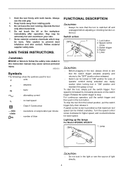
... supplier safety data. SAVE THESE INSTRUCTIONS. Switch action 1 4 5 3 2 1. Lock button 2. Speed control screw 3. To start the tool, simply pull the switch trigger. Release the switch trigger to the "OFF" position when released. • Switch can be sure that the tool is provided so that the switch trigger actuates properly and returns to stop the tool from rotating parts. 5. To stop . A speed control screw is switched off and unplugged before adjusting or checking function on the tool. Turn the speed control screw...
... supplier safety data. SAVE THESE INSTRUCTIONS. Switch action 1 4 5 3 2 1. Lock button 2. Speed control screw 3. To start the tool, simply pull the switch trigger. Release the switch trigger to the "OFF" position when released. • Switch can be sure that the tool is provided so that the switch trigger actuates properly and returns to stop the tool from rotating parts. 5. To stop . A speed control screw is switched off and unplugged before adjusting or checking function on the tool. Turn the speed control screw...
Owners Manual
Page 5
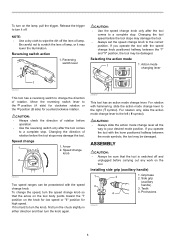
... (auxiliary handle) 1 3 2 4 1. Grip base 2. Release the trigger to turn it off the lens of lamp. Reversing switch lever A CAUTION: • Use the speed change 1 1. If you operate the tool with the speed change knob to the left ( symbol). Side grip (auxiliary handle) 3. Changing the tool speed before the tool stops may damage the tool. Speed change knob only after the tool comes to the right ( symbol). If it may damage the tool. • Always set the speed change knob. Changing the direction of...
... (auxiliary handle) 1 3 2 4 1. Grip base 2. Release the trigger to turn it off the lens of lamp. Reversing switch lever A CAUTION: • Use the speed change 1 1. If you operate the tool with the speed change knob to the left ( symbol). Side grip (auxiliary handle) 3. Changing the tool speed before the tool stops may damage the tool. Speed change knob only after the tool comes to the right ( symbol). If it may damage the tool. • Always set the speed change knob. Changing the direction of...
Owners Manual
Page 6
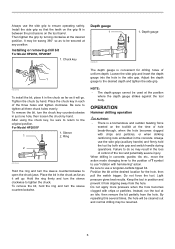
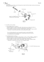
Installing or removing drill bit For Model HP2050, HP2050F 1. Place the chuck key in each of uniform depth. For Model HP2051F 1. Ring 2 002695 Hold the ring and turn the sleeve clockwise to open the chuck jaws. Hold the ring firmly and turn the sleeve counterclockwise to tighten the chuck. Do not force the tool. Then tighten the grip by hand. Depth gauge 1 002694 To install the bit, place it in the chuck as far...
Installing or removing drill bit For Model HP2050, HP2050F 1. Place the chuck key in each of uniform depth. For Model HP2051F 1. Ring 2 002695 Hold the ring and turn the sleeve clockwise to open the chuck jaws. Hold the ring firmly and turn the sleeve counterclockwise to tighten the chuck. Do not force the tool. Then tighten the grip by hand. Depth gauge 1 002694 To install the bit, place it in the chuck as far...
Owners Manual
Page 7
...; A stuck bit can be removed simply by setting the reversing switch to be drilled. Only use with a center-punch and hammer at the time of injury to back out. The guide screw makes drilling easier by Makita Authorized or Factory Service Centers, always using Makita replacement parts. In fact, this manual. Vent holes 1 002697 To maintain product SAFETY and RELIABILITY, repairs, carbon brush inspection and replacement, any assistance for its air vents have...
...; A stuck bit can be removed simply by setting the reversing switch to be drilled. Only use with a center-punch and hammer at the time of injury to back out. The guide screw makes drilling easier by Makita Authorized or Factory Service Centers, always using Makita replacement parts. In fact, this manual. Vent holes 1 002697 To maintain product SAFETY and RELIABILITY, repairs, carbon brush inspection and replacement, any assistance for its air vents have...
Owners Manual
Page 8
... by defective workmanship or material, Makita will repair (or at our option, replace) without charge. MAKITA DISCLAIMS LIABILITY FOR ANY IMPLIED WARRANTIES, INCLUDING IMPLIED WARRANTIES OF "MERCHANTABILITY" AND "FITNESS FOR A SPECIFIC PURPOSE," AFTER THE ONE YEAR TERM OF THIS WARRANTY. Some states do not allow the exclusion or limitation of Makita's Factory or Authorized Service Centers. EN0006-1 8 IN NO EVENT...
... by defective workmanship or material, Makita will repair (or at our option, replace) without charge. MAKITA DISCLAIMS LIABILITY FOR ANY IMPLIED WARRANTIES, INCLUDING IMPLIED WARRANTIES OF "MERCHANTABILITY" AND "FITNESS FOR A SPECIFIC PURPOSE," AFTER THE ONE YEAR TERM OF THIS WARRANTY. Some states do not allow the exclusion or limitation of Makita's Factory or Authorized Service Centers. EN0006-1 8 IN NO EVENT...
Parts Breakdown
Page 2
... LEVER B, HP2050F LOCK PLATE, HP2050F PIN 4, HP2050F LEAF SPRING, HP2030 RACK 12, HP2050F PIN 4, HP2050F CHANGE PLATE B, HP2050F RING 8, HP2050F BALL BEARING 608DDW, 9031 FAN 52, 6904VH ARMATURE ASSY 115V, HP2050F INSULATION WASHER, 9557PB BALL BEARING 607LLB, LS1013 LABYRINTH RUBBER RING,HR2455 BAFFLE PLATE, HP2050F TAPPING SCREW 4X65, HP2030 FIELD 115V, HP2050F MOTOR HOUSING,HP2050F HOUSING SET, HP2050F MAKITA LABEL, DA3010F BRUSH HOLDER,HP2050F CARBON BRUSH SET CB-407, BO5030K CARBON BRUSH SET CB-407, FS4200 NAME PLATE,HP2050F SPACER, HP2050F BRUSH HOLDER, HP2050F SWITCH, HP2050F HANDLE...
... LEVER B, HP2050F LOCK PLATE, HP2050F PIN 4, HP2050F LEAF SPRING, HP2030 RACK 12, HP2050F PIN 4, HP2050F CHANGE PLATE B, HP2050F RING 8, HP2050F BALL BEARING 608DDW, 9031 FAN 52, 6904VH ARMATURE ASSY 115V, HP2050F INSULATION WASHER, 9557PB BALL BEARING 607LLB, LS1013 LABYRINTH RUBBER RING,HR2455 BAFFLE PLATE, HP2050F TAPPING SCREW 4X65, HP2030 FIELD 115V, HP2050F MOTOR HOUSING,HP2050F HOUSING SET, HP2050F MAKITA LABEL, DA3010F BRUSH HOLDER,HP2050F CARBON BRUSH SET CB-407, BO5030K CARBON BRUSH SET CB-407, FS4200 NAME PLATE,HP2050F SPACER, HP2050F BRUSH HOLDER, HP2050F SWITCH, HP2050F HANDLE...

Parts Breakdown
Page 3
55 56 57 58 59 60 61 1,001 1,002 1,003 1,004 5,001 687063-9 265995-6 631476-6 682559-5 664891-9 345280-4 263002-9 324219-0 410102-8 824650-5 763430-3 810134-9 Parts Breakdown STRAIN RELIEF, 4323K TAPPING SCREW 4X18, 4323K LIGHT CIRCUIT, HP2050F CORD GUARD 8, 6824 CORD HEX. WASHER, HP2050F RUBBER PIN 4, HR2400 DEPTH GAUGE,HP2050F KEY HOLDER, 6013BR PLASTIC TOOL CASE, HP2050F CHUCK KEY S13, HP2040 CAUTION LABEL, 3709 HP2050F 1 2 1 1 1 1 1 1 1 1 1 1 Page 3 of 3 8/18/2010
55 56 57 58 59 60 61 1,001 1,002 1,003 1,004 5,001 687063-9 265995-6 631476-6 682559-5 664891-9 345280-4 263002-9 324219-0 410102-8 824650-5 763430-3 810134-9 Parts Breakdown STRAIN RELIEF, 4323K TAPPING SCREW 4X18, 4323K LIGHT CIRCUIT, HP2050F CORD GUARD 8, 6824 CORD HEX. WASHER, HP2050F RUBBER PIN 4, HR2400 DEPTH GAUGE,HP2050F KEY HOLDER, 6013BR PLASTIC TOOL CASE, HP2050F CHUCK KEY S13, HP2040 CAUTION LABEL, 3709 HP2050F 1 2 1 1 1 1 1 1 1 1 1 1 Page 3 of 3 8/18/2010

Technical Reference
Page 1
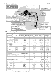
... job light Reverse switch Protection from electric shock No Yes No Yes Yes by double insulation Cord length : m ( ft ) Net weight :Kg (lbs ) 2.5 (8.2) 2.3 (5.1) Standard equipment * Chuck key S-13 (only for HP2050 and hP2050F 1 pc. * Key holder (only for HP2050 and hP2050F 1 pc. * Depth guide 1 pc. * Side grip set * Center drill bit for hole saw 16 - 90mm * Blow-out bulb * Type 43 drill stand * Chuck key S-13 (for the tool shown may...
... job light Reverse switch Protection from electric shock No Yes No Yes Yes by double insulation Cord length : m ( ft ) Net weight :Kg (lbs ) 2.5 (8.2) 2.3 (5.1) Standard equipment * Chuck key S-13 (only for HP2050 and hP2050F 1 pc. * Key holder (only for HP2050 and hP2050F 1 pc. * Depth guide 1 pc. * Side grip set * Center drill bit for hole saw 16 - 90mm * Blow-out bulb * Type 43 drill stand * Chuck key S-13 (for the tool shown may...
Technical Reference
Page 2
... design handle for better work efficiency 2-speed mechanical gear selection, High-Low Equipped with big trigger and speed control dial Lock-ON button for continuous operation LED job light for better maneuverability Sturdy aluminum gear housing P 2 / 17 Large lever has made it easy to change Palm fitting soft grip Variable speed control switch with torque limiter for protection of user and mechanism from accidental lock of products Cord guard is...
... design handle for better work efficiency 2-speed mechanical gear selection, High-Low Equipped with big trigger and speed control dial Lock-ON button for continuous operation LED job light for better maneuverability Sturdy aluminum gear housing P 2 / 17 Large lever has made it easy to change Palm fitting soft grip Variable speed control switch with torque limiter for protection of user and mechanism from accidental lock of products Cord guard is...
Technical Reference
Page 3
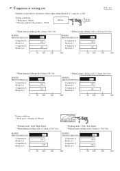
... fir * Working mode : Drill / High Speed * When hammer drilling with :ø 24 mm (15/16") bit MAKITA HP2050(F)/HP2051(F) Competitor A Model A-1 Competitor A Model A-2 120 100 120 * Working mode : Drill / Low Speed * When hammer drilling with ø 36mm (1-7/16") bit MAKITA HP2050(F)/HP2051(F) Competitor A Model A-1 Competitor A Model A-2 125 100 100 0 50 100 150 200 0 50 100 150 200 Comparison of working rate Numbers in chart below are relative values when setting Model A-1 's capacity...
... fir * Working mode : Drill / High Speed * When hammer drilling with :ø 24 mm (15/16") bit MAKITA HP2050(F)/HP2051(F) Competitor A Model A-1 Competitor A Model A-2 120 100 120 * Working mode : Drill / Low Speed * When hammer drilling with ø 36mm (1-7/16") bit MAKITA HP2050(F)/HP2051(F) Competitor A Model A-1 Competitor A Model A-2 125 100 100 0 50 100 150 200 0 50 100 150 200 Comparison of working rate Numbers in chart below are relative values when setting Model A-1 's capacity...
Technical Reference
Page 4
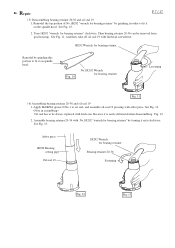
Gear housing Spur gear 29-37 Fig. 1 Change lever B < 2 >Assembling and disassembling ( 1 ) Disassembling drill chuck See Fig. 2. 1. Insert No.1R298 "hex wrench" into drill chuck and grip it firmly with pipe wrench. In case of broken drill chuck, it firmly with drill chuck. 3. Preset the torque level of No.1R223 "torque wrench" to the inner part of spindle with No.1R139 "drill chuck extractor" which No.1R224 "ratchet head" is fixed with vise 3. Turn No.1R298 "hex wrench" anti...
Gear housing Spur gear 29-37 Fig. 1 Change lever B < 2 >Assembling and disassembling ( 1 ) Disassembling drill chuck See Fig. 2. 1. Insert No.1R298 "hex wrench" into drill chuck and grip it firmly with pipe wrench. In case of broken drill chuck, it firmly with drill chuck. 3. Preset the torque level of No.1R223 "torque wrench" to the inner part of spindle with No.1R139 "drill chuck extractor" which No.1R224 "ratchet head" is fixed with vise 3. Turn No.1R298 "hex wrench" anti...

Technical Reference
Page 5
... change lever B, pin, rack 12 with change plate B to "( 6) Assembling bearing retainer 20-36 and oil seal 19" at page 7. 2. Insert change plate B and spur gear 29-37 can be disassembled from gear housing. 2. If not, assemble it. Fig. 6 Gear housing Leaf spring Spur gear 29-37 Spindle Rack 12 with change plate B into rack 12 as illustrated in advance. Separate gear housing cover from gear housing. Spur gear 29-37 4. Repair ( 3) Disassembling gear...
... change lever B, pin, rack 12 with change plate B to "( 6) Assembling bearing retainer 20-36 and oil seal 19" at page 7. 2. Insert change plate B and spur gear 29-37 can be disassembled from gear housing. 2. If not, assemble it. Fig. 6 Gear housing Leaf spring Spur gear 29-37 Spindle Rack 12 with change plate B into rack 12 as illustrated in advance. Separate gear housing cover from gear housing. Spur gear 29-37 4. Repair ( 3) Disassembling gear...

Technical Reference
Page 6
.... 8 and Fig. 8A. Spur gear 29-37 P 6 / 17 Spindle Change lever B 5. Assemble lock plate to gear housing with aligning its tail portion between ribs of gear housing. Keeping the above position of rack 12, assemble change lever B to gear housing with setting its "I" mark to the gear housing as illustrated in Fig. 9. Pin 4 Lock plate Fig. 8 Rack 12 Rib 5. Insert pin 4 through rack 12 into gear housing. Assemble gear complete to the triangle...
.... 8 and Fig. 8A. Spur gear 29-37 P 6 / 17 Spindle Change lever B 5. Assemble lock plate to gear housing with aligning its tail portion between ribs of gear housing. Keeping the above position of rack 12, assemble change lever B to gear housing with setting its "I" mark to the gear housing as illustrated in Fig. 9. Pin 4 Lock plate Fig. 8 Rack 12 Rib 5. Insert pin 4 through rack 12 into gear housing. Assemble gear complete to the triangle...
Technical Reference
Page 7
... Fig. 12 Fig. 13 Apply MAKITA grease N No.1 to be removed from gear housing. Fig. 12 2. Repair P 7 / 17 ( 5) Disassembling bearing retainer 20-36 and oil seal 19 1. Turn 1R292 "wrench for bearing retainer" by grinding, in order to fit it on spindle head. Assemble bearing retainer 20-36 with arbor press. Oil seal has to oil seal, and assemble oil seal 19 pressing with No...
... Fig. 12 Fig. 13 Apply MAKITA grease N No.1 to be removed from gear housing. Fig. 12 2. Repair P 7 / 17 ( 5) Disassembling bearing retainer 20-36 and oil seal 19 1. Turn 1R292 "wrench for bearing retainer" by grinding, in order to fit it on spindle head. Assemble bearing retainer 20-36 with arbor press. Oil seal has to oil seal, and assemble oil seal 19 pressing with No...
Technical Reference
Page 14
A LED Fig. B LED circuit Lead wire (blue ) of power supply cord * Grounding lead wire (transparent) for connecting to be set in the illustrated position. C Bottom view (View from cord guard side) Fix Lead wire (black) connecting field terminals A and B, with lead holder the lead wires passed through this portion, with lead holder Noise suppressor LED circuit Switch Fix the lead wires (white) of LED circuit, with...
A LED Fig. B LED circuit Lead wire (blue ) of power supply cord * Grounding lead wire (transparent) for connecting to be set in the illustrated position. C Bottom view (View from cord guard side) Fix Lead wire (black) connecting field terminals A and B, with lead holder the lead wires passed through this portion, with lead holder Noise suppressor LED circuit Switch Fix the lead wires (white) of LED circuit, with...

Technical Reference
Page 15
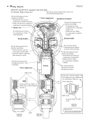
... terminal Brush holder Brush holder Fix the following lead wires with this lead holder. * Switch lead wire (blue) for connecting to brush holder * Field lead wire (white) for connecting to be set in the illustrated position. Wiring diagram P 15 / 17 HP2050 and HP2051 (without flash light) For Europe, High voltage area The electrical parts marked with * have to brush holder * Lead wire (black) connecting field terminals A and B Fix with lead holder the lead wires...
... terminal Brush holder Brush holder Fix the following lead wires with this lead holder. * Switch lead wire (blue) for connecting to brush holder * Field lead wire (white) for connecting to be set in the illustrated position. Wiring diagram P 15 / 17 HP2050 and HP2051 (without flash light) For Europe, High voltage area The electrical parts marked with * have to brush holder * Lead wire (black) connecting field terminals A and B Fix with lead holder the lead wires...

Technical Reference
Page 16
... lead holder. * Switch lead wire (red) for connecting to switch Fix with lead holder the lead wires passed through this portion Switch P 16 / 17 Fix choke coil lead wire (orange) with lead holders. Brush holder Fix the following lead wires with this portion Noise suppressor Wiring diagram HP2050 and HP2051 (without flash light) For Great Britain, low voltage Choke coil Set choke coil in the position illustrated. Brush holder Fix Lead wire (black...
... lead holder. * Switch lead wire (red) for connecting to switch Fix with lead holder the lead wires passed through this portion Switch P 16 / 17 Fix choke coil lead wire (orange) with lead holders. Brush holder Fix the following lead wires with this portion Noise suppressor Wiring diagram HP2050 and HP2051 (without flash light) For Great Britain, low voltage Choke coil Set choke coil in the position illustrated. Brush holder Fix Lead wire (black...

Technical Reference
Page 17
... lead holder. Brush holder Fix the following lead wires with this lead holder. * Switch lead wire (red) for connecting to switch, with lead holder. Wiring diagram HP2050 and HP2051 (without flash light) For other countries Fix field lead wire (black) for connecting to brush holder * Lead wire (black) connecting field terminals A and B Fix with lead holder the lead wires passed through this portion Noise suppressor Noise suppressor is not used in some...
... lead holder. Brush holder Fix the following lead wires with this lead holder. * Switch lead wire (red) for connecting to switch, with lead holder. Wiring diagram HP2050 and HP2051 (without flash light) For other countries Fix field lead wire (black) for connecting to brush holder * Lead wire (black) connecting field terminals A and B Fix with lead holder the lead wires passed through this portion Noise suppressor Noise suppressor is not used in some...


