
Owners Manual
Page 7
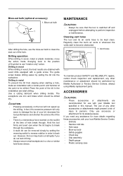
... when drilling metals. However, the tool may back out abruptly if you need any assistance for more details regarding these accessories, ask your local Makita Service Center. • Drill bits • Hammer drill bits • Hole saws • Blow-out bulb • Safety goggles •...in this excessive pressure will not speed up the drilling. Vent holes 1 002697 To maintain product SAFETY and RELIABILITY, repairs, carbon brush inspection and replacement, any other maintenance or adjustment should be removed simply by setting the reversing switch to reverse rotation in a vise...
... when drilling metals. However, the tool may back out abruptly if you need any assistance for more details regarding these accessories, ask your local Makita Service Center. • Drill bits • Hammer drill bits • Hole saws • Blow-out bulb • Safety goggles •...in this excessive pressure will not speed up the drilling. Vent holes 1 002697 To maintain product SAFETY and RELIABILITY, repairs, carbon brush inspection and replacement, any other maintenance or adjustment should be removed simply by setting the reversing switch to reverse rotation in a vise...
Parts Breakdown
Page 2
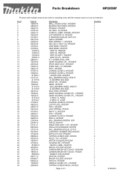
... BALL BEARING 607LLB, LS1013 LABYRINTH RUBBER RING,HR2455 BAFFLE PLATE, HP2050F TAPPING SCREW 4X65, HP2030 FIELD 115V, HP2050F MOTOR HOUSING,HP2050F HOUSING SET, HP2050F MAKITA LABEL, DA3010F BRUSH HOLDER,HP2050F CARBON BRUSH SET CB-407, BO5030K CARBON BRUSH SET CB-407, FS4200 NAME PLATE,HP2050F SPACER, HP2050F BRUSH HOLDER, HP2050F SWITCH, HP2050F HANDLE COVER CPL., HP2050F TAPPING SCREW M4X25, HM1800 Page 2 of 3 Quantity 1 1 1 1 1 1 1 1 1 1 1 1 1 1 1 1 3 1 1 1 1 1 1 1 1 1 1 1 1 1 1 1 1 1 1 1 1 1 1 1 1 1 1 1 1 1 1 1 1 1 2 1 1 1 1 1 1 1 1 2 1 1 1 3 8/18/2010...
... BALL BEARING 607LLB, LS1013 LABYRINTH RUBBER RING,HR2455 BAFFLE PLATE, HP2050F TAPPING SCREW 4X65, HP2030 FIELD 115V, HP2050F MOTOR HOUSING,HP2050F HOUSING SET, HP2050F MAKITA LABEL, DA3010F BRUSH HOLDER,HP2050F CARBON BRUSH SET CB-407, BO5030K CARBON BRUSH SET CB-407, FS4200 NAME PLATE,HP2050F SPACER, HP2050F BRUSH HOLDER, HP2050F SWITCH, HP2050F HANDLE COVER CPL., HP2050F TAPPING SCREW M4X25, HM1800 Page 2 of 3 Quantity 1 1 1 1 1 1 1 1 1 1 1 1 1 1 1 1 3 1 1 1 1 1 1 1 1 1 1 1 1 1 1 1 1 1 1 1 1 1 1 1 1 1 1 1 1 1 1 1 1 1 2 1 1 1 1 1 1 1 1 2 1 1 1 3 8/18/2010...
Technical Reference
Page 10
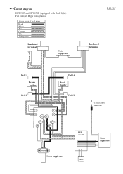
Circuit diagram HP2050F and HP2051F (equipped with flash light) For Europe, High voltage area Color index of lead wires Black White Red Orange Blue Transparent Insulated terminal Noise suppressor P 10 / 17 Insulated terminal Choke coil Field A Brush holder Field B Field A Brush holder Field B 2 3 4 1 M1 M2 C1 1 C2 2 LED circuit Connected to field core Noise suppressor Power supply cord LED
Circuit diagram HP2050F and HP2051F (equipped with flash light) For Europe, High voltage area Color index of lead wires Black White Red Orange Blue Transparent Insulated terminal Noise suppressor P 10 / 17 Insulated terminal Choke coil Field A Brush holder Field B Field A Brush holder Field B 2 3 4 1 M1 M2 C1 1 C2 2 LED circuit Connected to field core Noise suppressor Power supply cord LED

Technical Reference
Page 11
Circuit diagram HP2050 and HP2051 (without flash light) For Europe, High voltage area Color index of lead wires Black White Red Orange Blue Transparent Insulated terminal Noise suppressor P 11 / 17 Insulated terminal Choke coil Field A Brush holder Field B Field A Brush holder Field B 2 3 4 1 M1 M2 C1 1 C2 2 Power supply cord Connected to field core Noise suppressor
Circuit diagram HP2050 and HP2051 (without flash light) For Europe, High voltage area Color index of lead wires Black White Red Orange Blue Transparent Insulated terminal Noise suppressor P 11 / 17 Insulated terminal Choke coil Field A Brush holder Field B Field A Brush holder Field B 2 3 4 1 M1 M2 C1 1 C2 2 Power supply cord Connected to field core Noise suppressor

Technical Reference
Page 12
Circuit diagram HP2050 and HP2051 (without flash light) For Great Britain, low voltage Color index of lead wires Black White Red Orange Blue Transparent P 12 / 17 Choke coil Field A Brush holder Field B Field A Brush holder Field B 2 3 4 1 M1 M2 C1 1 C2 2 Connected to field core Noise suppressor Power supply cord
Circuit diagram HP2050 and HP2051 (without flash light) For Great Britain, low voltage Color index of lead wires Black White Red Orange Blue Transparent P 12 / 17 Choke coil Field A Brush holder Field B Field A Brush holder Field B 2 3 4 1 M1 M2 C1 1 C2 2 Connected to field core Noise suppressor Power supply cord

Technical Reference
Page 13
Circuit diagram HP2050 and HP2051 (without flash light) For other countries Color index of lead wires Black White Red Orange Blue P 13 / 17 Field A Brush holder Field B Field A Brush holder Field B 2 3 4 1 M1 M2 C1 1 C2 2 Noise suppressor Power supply cord
Circuit diagram HP2050 and HP2051 (without flash light) For other countries Color index of lead wires Black White Red Orange Blue P 13 / 17 Field A Brush holder Field B Field A Brush holder Field B 2 3 4 1 M1 M2 C1 1 C2 2 Noise suppressor Power supply cord
Technical Reference
Page 14
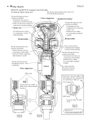
... with * have to field core Noise suppressor Fig. See Fig. C Bottom view (View from cord guard side) Wiring diagram P 14 / 17 HP2050F and HP2051F (equipped with flash light) For Europe, High voltage area The electrical parts marked with lead holder. B LED circuit Lead wire (blue )...Choke coil lead wire (orange) for connecting to insulated terminal * Choke coil Fix field lead wire (black) for connecting to insulated terminal Brush holder Brush holder Fix the following lead wires with lead holder. A LED Fig. A. Fix the following lead wires with this lead holder. * ...
... with * have to field core Noise suppressor Fig. See Fig. C Bottom view (View from cord guard side) Wiring diagram P 14 / 17 HP2050F and HP2051F (equipped with flash light) For Europe, High voltage area The electrical parts marked with lead holder. B LED circuit Lead wire (blue )...Choke coil lead wire (orange) for connecting to insulated terminal * Choke coil Fix field lead wire (black) for connecting to insulated terminal Brush holder Brush holder Fix the following lead wires with lead holder. A LED Fig. A. Fix the following lead wires with this lead holder. * ...

Technical Reference
Page 15
Fix the following lead wires with this lead holder. * Switch lead wire (red) for connecting to brush holder * Lead wire (black) connecting field terminals A and B Fix with lead holder the lead wires passed through this portion Switch Fix Lead wire (black) connecting ...field terminals A and B, with lead holder the lead wires passed through this lead holder. * Switch lead wire (blue) for connecting to brush holder * Field lead wire (white) for connecting to insulated terminal Fix with lead holder. Fix the following lead wires with this lead holder. * Switch lead...
Fix the following lead wires with this lead holder. * Switch lead wire (red) for connecting to brush holder * Lead wire (black) connecting field terminals A and B Fix with lead holder the lead wires passed through this portion Switch Fix Lead wire (black) connecting ...field terminals A and B, with lead holder the lead wires passed through this lead holder. * Switch lead wire (blue) for connecting to brush holder * Field lead wire (white) for connecting to insulated terminal Fix with lead holder. Fix the following lead wires with this lead holder. * Switch lead...

Technical Reference
Page 16
...this portion Switch P 16 / 17 Fix choke coil lead wire (orange) with lead holders. Brush holder Fix the following lead wires with this lead holder. * Switch lead wire (blue) for connecting to brush holder * Field lead wire (white) for connecting to field core, with lead holder the ...lead holder. Wiring diagram HP2050 and HP2051 (without flash light) For Great Britain, low voltage Choke coil Set choke coil in the position illustrated. Brush holder Fix Lead wire (black) connecting field terminals A and B, with lead holder. Fix the following lead wires with this lead holder. * Switch...
...this portion Switch P 16 / 17 Fix choke coil lead wire (orange) with lead holders. Brush holder Fix the following lead wires with this lead holder. * Switch lead wire (blue) for connecting to brush holder * Field lead wire (white) for connecting to field core, with lead holder the ...lead holder. Wiring diagram HP2050 and HP2051 (without flash light) For Great Britain, low voltage Choke coil Set choke coil in the position illustrated. Brush holder Fix Lead wire (black) connecting field terminals A and B, with lead holder. Fix the following lead wires with this lead holder. * Switch...

Technical Reference
Page 17
... the following lead wires with this lead holder. * Switch lead wire (red) for connecting to brush holder * Lead wire (black) connecting field terminals A and B Fix with lead holder the lead wires passed through this portion Noise suppressor Noise suppressor is not ... switch, with lead holder the lead wires passed through this portion Switch P 17 / 17 Fix Lead wire (black) connecting field terminals A and B, with lead holder. Brush holder Fix the following lead wires with this lead holder. * Switch lead wire (blue) for connecting to...
... the following lead wires with this lead holder. * Switch lead wire (red) for connecting to brush holder * Lead wire (black) connecting field terminals A and B Fix with lead holder the lead wires passed through this portion Noise suppressor Noise suppressor is not ... switch, with lead holder the lead wires passed through this portion Switch P 17 / 17 Fix Lead wire (black) connecting field terminals A and B, with lead holder. Brush holder Fix the following lead wires with this lead holder. * Switch lead wire (blue) for connecting to...
