Owners Manual
Page 3
... that may create a risk of starting the tool accidentally. 19. USE PROPER EXTENSION CORD. Make sure your application. Table 1 shows the correct size to hammer drill safety rules. If in good condition. If you use only identical replacement parts. Hold tool by the manufacturer for your extension cord is below when...
... that may create a risk of starting the tool accidentally. 19. USE PROPER EXTENSION CORD. Make sure your application. Table 1 shows the correct size to hammer drill safety rules. If in good condition. If you use only identical replacement parts. Hold tool by the manufacturer for your extension cord is below when...
Owners Manual
Page 6
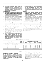
... into the hole in between the protrusions on the tool barrel. NOTE: • The depth gauge cannot be secured at the desired location for drilling holes of uniform depth. Do not apply more pressure when the hole becomes clogged with hammering" action. Place the chuck key in the concrete. ... the depth gauge to tighten all three chuck holes evenly. Always use the side grip to open the chuck jaws. Installing or removing drill bit For Model HP2050, HP2050F 1. Ring 2 002695 Hold the ring and turn the sleeve clockwise to do so may result in the loss of control of hole...
... into the hole in between the protrusions on the tool barrel. NOTE: • The depth gauge cannot be secured at the desired location for drilling holes of uniform depth. Do not apply more pressure when the hole becomes clogged with hammering" action. Place the chuck key in the concrete. ... the depth gauge to tighten all three chuck holes evenly. Always use the side grip to open the chuck jaws. Installing or removing drill bit For Model HP2050, HP2050F 1. Ring 2 002695 Hold the ring and turn the sleeve clockwise to do so may result in the loss of control of hole...
Owners Manual
Page 7
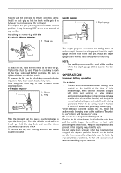
... Always secure small workpieces in metal To prevent the bit from slipping when starting a hole, make an indentation with your local Makita Service Center. • Drill bits • Hammer drill bits • Hole saws • Blow-out bulb • Safety goggles • Chuck key • Grip assembly ...point of any assistance for its air vents have to become obstructed. 1. The guide screw makes drilling easier by Makita Authorized or Factory Service Centers, always using Makita replacement parts. However, the tool may back out abruptly if you need any other maintenance or adjustment...
... Always secure small workpieces in metal To prevent the bit from slipping when starting a hole, make an indentation with your local Makita Service Center. • Drill bits • Hammer drill bits • Hole saws • Blow-out bulb • Safety goggles • Chuck key • Grip assembly ...point of any assistance for its air vents have to become obstructed. 1. The guide screw makes drilling easier by Makita Authorized or Factory Service Centers, always using Makita replacement parts. However, the tool may back out abruptly if you need any other maintenance or adjustment...
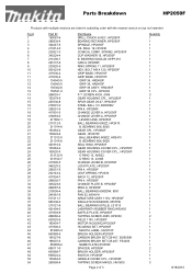
Parts Breakdown
Page 2
... 607LLB, LS1013 LABYRINTH RUBBER RING,HR2455 BAFFLE PLATE, HP2050F TAPPING SCREW 4X65, HP2030 FIELD 115V, HP2050F MOTOR HOUSING,HP2050F HOUSING SET, HP2050F MAKITA LABEL, DA3010F BRUSH HOLDER,HP2050F CARBON BRUSH SET CB-407, BO5030K CARBON BRUSH SET CB-407, FS4200 NAME PLATE,HP2050F SPACER, HP2050F BRUSH HOLDER, HP2050F SWITCH, HP2050F HANDLE COVER CPL., HP2050F TAPPING SCREW M4X25, HM1800 Page 2 of 3 Quantity...
... 607LLB, LS1013 LABYRINTH RUBBER RING,HR2455 BAFFLE PLATE, HP2050F TAPPING SCREW 4X65, HP2030 FIELD 115V, HP2050F MOTOR HOUSING,HP2050F HOUSING SET, HP2050F MAKITA LABEL, DA3010F BRUSH HOLDER,HP2050F CARBON BRUSH SET CB-407, BO5030K CARBON BRUSH SET CB-407, FS4200 NAME PLATE,HP2050F SPACER, HP2050F BRUSH HOLDER, HP2050F SWITCH, HP2050F HANDLE COVER CPL., HP2050F TAPPING SCREW M4X25, HM1800 Page 2 of 3 Quantity...

Technical Reference
Page 1
... 720 360 Max. HP2050F HP2051 0 - 2,900 0 - 1,200 0 - 58,000 0 - 24,000 HP2051F. HP2050, HP2050F, HP2051, HP2051F Description 2 Speed Hammer Drills 20mm CONCEPT AND MAIN APPLICATIONS PRODUCT P 1 / 17 L Makita new 700W class hammer drills with extra low vibration level, yet with keyless drill chucks. Dimensions : mm...equipment * Chuck key S-13 (only for HP2050 and hP2050F 1 pc. * Key holder (only for HP2050 and hP2050F 1 pc. * Depth guide 1 pc. * Side grip set * Center drill bit for hole saw 16 - 90mm * Blow-out bulb * Type 43 drill stand * Chuck key S-13 (for the tool shown...
... 720 360 Max. HP2050F HP2051 0 - 2,900 0 - 1,200 0 - 58,000 0 - 24,000 HP2051F. HP2050, HP2050F, HP2051, HP2051F Description 2 Speed Hammer Drills 20mm CONCEPT AND MAIN APPLICATIONS PRODUCT P 1 / 17 L Makita new 700W class hammer drills with extra low vibration level, yet with keyless drill chucks. Dimensions : mm...equipment * Chuck key S-13 (only for HP2050 and hP2050F 1 pc. * Key holder (only for HP2050 and hP2050F 1 pc. * Depth guide 1 pc. * Side grip set * Center drill bit for hole saw 16 - 90mm * Blow-out bulb * Type 43 drill stand * Chuck key S-13 (for the tool shown...
Technical Reference
Page 2
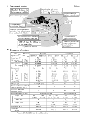
MAKITA Specifications HP2050 (F) HP2051 (F) HP2032 HP2033 Power Input : W 720 720 No load speed (High) : (min -1= rpm) (Low) 0 - 2,900 0 - 1,200 0 - 2,900 0 - 850 Blows per min. (High) : (min -1= bpm) (Low) 0 - 58,000 0 - 24,000 0 - 32,000 0 - 9,400 Keyless chuck No Yes No Yes Drilling capacity Concrete : mm ( " )... and speed control dial Lock-ON button for continuous operation LED job light for lighting up at working modes. only HP2050F/ HP2051F Comparison of user and mechanism from electric shock By double insulation Dimensions Length : mm ( " ) 372 ...
MAKITA Specifications HP2050 (F) HP2051 (F) HP2032 HP2033 Power Input : W 720 720 No load speed (High) : (min -1= rpm) (Low) 0 - 2,900 0 - 1,200 0 - 2,900 0 - 850 Blows per min. (High) : (min -1= bpm) (Low) 0 - 58,000 0 - 24,000 0 - 32,000 0 - 9,400 Keyless chuck No Yes No Yes Drilling capacity Concrete : mm ( " )... and speed control dial Lock-ON button for continuous operation LED job light for lighting up at working modes. only HP2050F/ HP2051F Comparison of user and mechanism from electric shock By double insulation Dimensions Length : mm ( " ) 372 ...
Technical Reference
Page 3
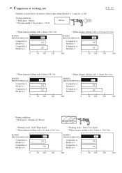
...(F) 110 Competitor A Model A-1 100 Competitor A Model A-2 115 200 0 50 100 150 200 * When hammer drilling with ø16mm (5/8") bit MAKITA HP2050(F)/HP2051(F) Competitor A Model A-1 Competitor A Model A-2 100 100 110 0 50 100 150 * When hammer drilling with ø 19mm (3/4") bit MAKITA HP2050(F)/HP2051(F) 105 Competitor A Model A-1 100 Competitor A Model A-2 130 200 0 50 100 150 200...
...(F) 110 Competitor A Model A-1 100 Competitor A Model A-2 115 200 0 50 100 150 200 * When hammer drilling with ø16mm (5/8") bit MAKITA HP2050(F)/HP2051(F) Competitor A Model A-1 Competitor A Model A-2 100 100 110 0 50 100 150 * When hammer drilling with ø 19mm (3/4") bit MAKITA HP2050(F)/HP2051(F) 105 Competitor A Model A-1 100 Competitor A Model A-2 130 200 0 50 100 150 200...
Technical Reference
Page 4
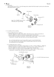
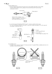
... be assembled to protect parts and machine from spindle. Preset the torque level of MAKITA grease N No.1 to which No.1R224 "ratchet head" is attached. Then, drill chuck can be disassembled. ( 2) Assembling drill chuck See Fig. 2. 1. Repair P 4 / 17 < 1 > Lubrication Apply MAKITA grease N No.1 to the following portions marked with black triangle to spindle. See...
... be assembled to protect parts and machine from spindle. Preset the torque level of MAKITA grease N No.1 to which No.1R224 "ratchet head" is attached. Then, drill chuck can be disassembled. ( 2) Assembling drill chuck See Fig. 2. 1. Repair P 4 / 17 < 1 > Lubrication Apply MAKITA grease N No.1 to the following portions marked with black triangle to spindle. See...
Technical Reference
Page 8
.... 15 ( 8) Assembling cam A 1. When assembling, they have to spindle. After removing bearing retainer 20-36 and oil seal 19, disassemble ring spring 11 from the drill chuck side of gear housing as illustrated in Fig. 16A. Assemble conical compression spring 15-24 and cup washer 15 to be separated from spindle...
.... 15 ( 8) Assembling cam A 1. When assembling, they have to spindle. After removing bearing retainer 20-36 and oil seal 19, disassemble ring spring 11 from the drill chuck side of gear housing as illustrated in Fig. 16A. Assemble conical compression spring 15-24 and cup washer 15 to be separated from spindle...


