

Owners Manual
Page 2
.... KNOW YOUR POWER TOOL. Read the owner's manual carefully. KEEP WORK AREA CLEAN. Learn the tool's applications and limitations, as well as the specific potential hazards peculiar to EPTA-Procedure 01/2003 For Your Own Safety Read Instruction Manual USA005-3 Before Operating Tool Save it for future reference GENERAL SAFETY PRECAUTIONS (For All Tools) 1. KEEP GUARDS IN PLACE and in damp or wet 2 Miter angle Left 47...
.... KNOW YOUR POWER TOOL. Read the owner's manual carefully. KEEP WORK AREA CLEAN. Learn the tool's applications and limitations, as well as the specific potential hazards peculiar to EPTA-Procedure 01/2003 For Your Own Safety Read Instruction Manual USA005-3 Before Operating Tool Save it for future reference GENERAL SAFETY PRECAUTIONS (For All Tools) 1. KEEP GUARDS IN PLACE and in damp or wet 2 Miter angle Left 47...
Owners Manual
Page 3
... if cutting operation is in moving parts, breakage of injury to contain long hair. 11. Everyday eyeglasses only have the switch on invites accidents. 23. REDUCE THE RISK OF UNINTENTIONAL STARTING. TURN POWER OFF. Inserting the battery cartridge into a blade or cutter against the direction of rotation of any coasting blade. Use power tools only with the charger specified by a qualified repair person using only identical replacement parts. Use of the blade...
... if cutting operation is in moving parts, breakage of injury to contain long hair. 11. Everyday eyeglasses only have the switch on invites accidents. 23. REDUCE THE RISK OF UNINTENTIONAL STARTING. TURN POWER OFF. Inserting the battery cartridge into a blade or cutter against the direction of rotation of any coasting blade. Use power tools only with the charger specified by a qualified repair person using only identical replacement parts. Use of the blade...
Owners Manual
Page 4
... these parts could indicate poor installation or a poorly balanced blade. 25. Never clamp or tie the blade guard into an electrical outlet. 12. Never use tool where operator positioning would be secured firmly against the turn base in the "ON" position. 28. While making a slide cut and release switch immediately. 15. Be careful not to secure workpiece. 000030 4 For your hand to stop before operation. 20. Hold the handle firmly...
... these parts could indicate poor installation or a poorly balanced blade. 25. Never clamp or tie the blade guard into an electrical outlet. 12. Never use tool where operator positioning would be secured firmly against the turn base in the "ON" position. 28. While making a slide cut and release switch immediately. 15. Be careful not to secure workpiece. 000030 4 For your hand to stop before operation. 20. Hold the handle firmly...
Owners Manual
Page 5
... Turn the adjusting bolt clockwise or counterclockwise so that the tool will help prevent tipping and possible injury. 1 1. Before using battery cartridge, read all instructions and cautionary markings on the handle and pulling the stopper pin. 1. A battery short can explode in loss of the miter saw on the supporting surface while cutting may reach or exceed 50 ゚ C (122 ゚ F). 7. INSTALLATION Bench mounting When the tool...
... Turn the adjusting bolt clockwise or counterclockwise so that the tool will help prevent tipping and possible injury. 1 1. Before using battery cartridge, read all instructions and cautionary markings on the handle and pulling the stopper pin. 1. A battery short can explode in loss of the miter saw on the supporting surface while cutting may reach or exceed 50 ゚ C (122 ゚ F). 7. INSTALLATION Bench mounting When the tool...
Owners Manual
Page 6
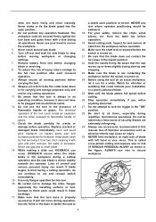
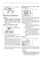
... accidental start-up. Installing or removing battery cartridge 2 3 1 1. Red part 2. The tool stops during operation. 6 At this time, stop use force when inserting the battery cartridge. Button 3. Always insert it all the way until the red part cannot be sure that the tool is overloaded: At this time, remove the battery cartridge from the tool. • When the remaining battery capacity gets low: If any operation of the switch trigger, the motor will remain stopped...
... accidental start-up. Installing or removing battery cartridge 2 3 1 1. Red part 2. The tool stops during operation. 6 At this time, stop use force when inserting the battery cartridge. Button 3. Always insert it all the way until the red part cannot be sure that the tool is overloaded: At this time, remove the battery cartridge from the tool. • When the remaining battery capacity gets low: If any operation of the switch trigger, the motor will remain stopped...
Owners Manual
Page 7
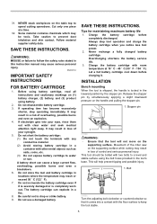
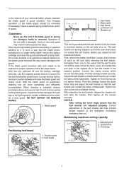
... setting the bevel angle ensure that the saw blade does not contact the kerf boards. Guide fence 3. With the blade guard so positioned, cleaning can still be more completely and efficiently accomplished. Before use the tool if the blade guard or spring are adjusted properly. Loosen two clamp screws which secure the slide poles. Turn base 2 3 011265 1 2 011240 7 WARNING: • Never use , adjust the kerf boards as follows: First, remove the battery cartridge. Blade teeth...
... setting the bevel angle ensure that the saw blade does not contact the kerf boards. Guide fence 3. With the blade guard so positioned, cleaning can still be more completely and efficiently accomplished. Before use the tool if the blade guard or spring are adjusted properly. Loosen two clamp screws which secure the slide poles. Turn base 2 3 011265 1 2 011240 7 WARNING: • Never use , adjust the kerf boards as follows: First, remove the battery cartridge. Blade teeth...
Owners Manual
Page 8
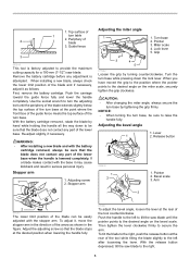
... direction of the tool counterclockwise. With the battery cartridge removed, rotate the blade by hand while holding the handle all the way down the lock lever. WARNING: • After installing a new blade and with the battery cartridge removed, always be easily adjusted with the base it may cause kickback and result in the figure. Adjusting screw 2. Turn base 2. Pointer 3. Grip 011242 Loosen the grip by tightening the grip firmly. Turn the turn base. Adjusting...
... direction of the tool counterclockwise. With the battery cartridge removed, rotate the blade by hand while holding the handle all the way down the lock lever. WARNING: • After installing a new blade and with the battery cartridge removed, always be easily adjusted with the base it may cause kickback and result in the figure. Adjusting screw 2. Turn base 2. Pointer 3. Grip 011242 Loosen the grip by tightening the grip firmly. Turn the turn base. Adjusting...
Owners Manual
Page 9
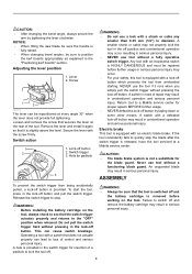
... switch trigger for proper repairs BEFORE further usage. • NEVER defeat the lock-off button. Never use the tool if it is released, have the tool serviced at the rear of control and serious personal injury. CAUTION: • After changing the bevel angle, always secure the arm by taping down or some other means. Secure the lever with an electric blade brake. WARNING: • Before installing the battery...
... switch trigger for proper repairs BEFORE further usage. • NEVER defeat the lock-off button. Never use the tool if it is released, have the tool serviced at the rear of control and serious personal injury. CAUTION: • After changing the bevel angle, always secure the arm by taping down or some other means. Secure the lever with an electric blade brake. WARNING: • Before installing the battery...
Owners Manual
Page 10
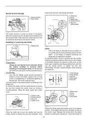
... pin. Arrow 3. Hex bolt (left -handed) securely counterclockwise while pressing the shaft lock. 1. To install the blade, mount it counterclockwise. Socket wrench 5. Socket wrench 3. Install the outer flange and hex bolt, and then use the socket wrench to install it can be stored by turning it carefully onto the spindle, making sure that the tool is switched off and the battery cartridge is removed be sure that the direction...
... pin. Arrow 3. Hex bolt (left -handed) securely counterclockwise while pressing the shaft lock. 1. To install the blade, mount it counterclockwise. Socket wrench 5. Socket wrench 3. Install the outer flange and hex bolt, and then use the socket wrench to install it can be stored by turning it carefully onto the spindle, making sure that the tool is switched off and the battery cartridge is removed be sure that the direction...
Owners Manual
Page 11
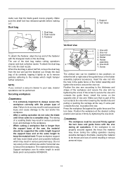
... vise knob. Proper workpiece support will help avoid blade pinch and possible kickback which might hamper further collection. Vise arm 2. Screw 5 002255 The vertical vise can be installed in serious personal injury. Position the vise arm according to secure the vise rod. Make sure the shaft lock has released spindle before making 1 cut. Dust bag 2 1. Dust bag 2. The use of the saw , cleaner operations...
... vise knob. Proper workpiece support will help avoid blade pinch and possible kickback which might hamper further collection. Vise arm 2. Screw 5 002255 The vertical vise can be installed in serious personal injury. Position the vise arm according to secure the vise rod. Make sure the shaft lock has released spindle before making 1 cut. Dust bag 2 1. Dust bag 2. The use of the saw , cleaner operations...
Owners Manual
Page 12
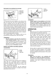
... switch is released, before turning again gently clockwise. Vise knob 2. In this case, turn the vise knob gently clockwise until the screw is turned on with the workpiece may stop at the topmost position. Proper workpiece support will be impaired. • During a slide cut, gently push the carriage toward the guide fence without significant decrease in contact with the blade in blade speed. • Gently press down the handle...
... switch is released, before turning again gently clockwise. Vise knob 2. In this case, turn the vise knob gently clockwise until the screw is turned on with the workpiece may stop at the topmost position. Proper workpiece support will be impaired. • During a slide cut, gently push the carriage toward the guide fence without significant decrease in contact with the blade in blade speed. • Gently press down the handle...
Owners Manual
Page 13
... applying pressure in serious personal injury. 2. Bevel cut 011245 Loosen two clamp screws which secure the slide poles clockwise to its fully elevated position. Make sure the carriage is completed, switch off the tool and WAIT UNTIL 011246 Loosen the lever and tilt the saw blade to set the bevel angle (Refer to secure the selected bevel angle safely. Push the carriage toward the guide fence. Slide (push) cutting (cutting wide...
... applying pressure in serious personal injury. 2. Bevel cut 011245 Loosen two clamp screws which secure the slide poles clockwise to its fully elevated position. Make sure the carriage is completed, switch off the tool and WAIT UNTIL 011246 Loosen the lever and tilt the saw blade to set the bevel angle (Refer to secure the selected bevel angle safely. Push the carriage toward the guide fence. Slide (push) cutting (cutting wide...
Owners Manual
Page 14
... be raised until it is changed during the cutting operation may result in serious personal injury. Always use several pieces for angle of left bevel cut . WARNING: • After setting the blade for a bevel cut, before operating the tool ensure that cut -off may confuse the operator as wall length. In the case of cut Table (A) Molding Bevel angle position in Fig. Outside corner Fig.A 001556 (1) (2) (3) (4) 1 2 1. Compound cutting can be performed at the back...
... be raised until it is changed during the cutting operation may result in serious personal injury. Always use several pieces for angle of left bevel cut . WARNING: • After setting the blade for a bevel cut, before operating the tool ensure that cut -off may confuse the operator as wall length. In the case of cut Table (A) Molding Bevel angle position in Fig. Outside corner Fig.A 001556 (1) (2) (3) (4) 1 2 1. Compound cutting can be performed at the back...
Owners Manual
Page 18
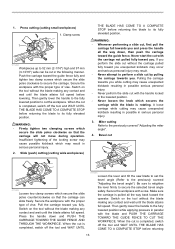
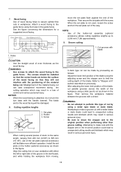
... facing Use of the holder-rod assembly (optional accessory) allows cutting repetitive lengths up to limit the cutting depth of the material being cut can be damaged. 8. NOTE: • Use of wood facing helps to the guide fence using a wider type blade or dado blade. See the figure concerning the dimensions for a suggested wood facing. 7. Attach a wood facing to assure splinter-free cuts in the guide fence. Refer to the guide fence. After adjusting...
... facing Use of the holder-rod assembly (optional accessory) allows cutting repetitive lengths up to limit the cutting depth of the material being cut can be damaged. 8. NOTE: • Use of wood facing helps to the guide fence using a wider type blade or dado blade. See the figure concerning the dimensions for a suggested wood facing. 7. Attach a wood facing to assure splinter-free cuts in the guide fence. Refer to the guide fence. After adjusting...
Owners Manual
Page 19
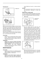
... or maintenance. MAINTENANCE CAUTION: • Always be sure that the battery cartridge is removed before carrying the tool. Turn the turn base in the stopper pin. Then turn the turn base slightly clockwise and counterclockwise to seat the turn base so that the pointer points to 0° on the guide fence in the stopper pin. If your tool is sharp and clean for cutting operations may have affected the alignment. Miter angle...
... or maintenance. MAINTENANCE CAUTION: • Always be sure that the battery cartridge is removed before carrying the tool. Turn the turn base in the stopper pin. Then turn the turn base slightly clockwise and counterclockwise to seat the turn base so that the pointer points to 0° on the guide fence in the stopper pin. If your tool is sharp and clean for cutting operations may have affected the alignment. Miter angle...
Owners Manual
Page 20
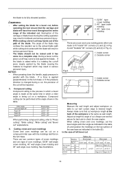
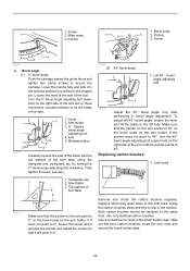
... (2) 45° bevel angle 1. Use only identical carbon brushes. Screw 1. Bevel angle (1) 0° bevel angle Push the carriage toward the guide fence and tighten two clamp screws to 0° on the bevel scale on the right side of 2 turn base using the triangular rule, try-square, etc. Left 45 ゚ bevel angle adjusting bolt 1 003945 Adjust the 45° bevel angle only after performing 0° bevel angle adjustment. Replacing carbon brushes 1. Saw blade 3. Triangular rule 1 2. Limit mark 1 001145 Remove and check the carbon brushes regularly. Pointer...
... (2) 45° bevel angle 1. Use only identical carbon brushes. Screw 1. Bevel angle (1) 0° bevel angle Push the carriage toward the guide fence and tighten two clamp screws to 0° on the bevel scale on the right side of 2 turn base using the triangular rule, try-square, etc. Left 45 ゚ bevel angle adjusting bolt 1 003945 Adjust the 45° bevel angle only after performing 0° bevel angle adjustment. Replacing carbon brushes 1. Saw blade 3. Triangular rule 1 2. Limit mark 1 001145 Remove and check the carbon brushes regularly. Pointer...
Owners Manual
Page 21
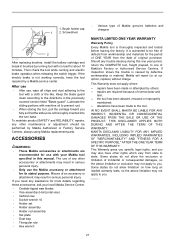
... and materials for use , wipe off chips and dust adhering to one of Makita genuine batteries and chargers MAKITA LIMITED ONE YEAR WARRANTY Warranty Policy Every Makita tool is caused by running and electric brake operation when releasing the switch trigger. After use • After use with no load for its stated purpose. To maintain product SAFETY and RELIABILITY, repairs, any trouble develop during this manual. Brush holder cap 1 2. Screwdriver 2 011307 After replacing brushes, install the battery cartridge and...
... and materials for use , wipe off chips and dust adhering to one of Makita genuine batteries and chargers MAKITA LIMITED ONE YEAR WARRANTY Warranty Policy Every Makita tool is caused by running and electric brake operation when releasing the switch trigger. After use • After use with no load for its stated purpose. To maintain product SAFETY and RELIABILITY, repairs, any trouble develop during this manual. Brush holder cap 1 2. Screwdriver 2 011307 After replacing brushes, install the battery cartridge and...

Parts Breakdown
Page 3
Parts Breakdown LXSL01 Products with multiple versions are listed in ...LEVER PIN 5 TERMINAL SWITCH TG72BD SWITCH LEVER TAPPING SCREW 4X18 REAR COVER LXSL01 NAME PLATE BRUSH HOLDER BRUSH HOLDER CARBON BRUSH CB-441 BRUSH HOLDER CAP MOTOR HOUSING TAPPING SCREW 4X60 PAN HEAD SCREW M5X45 HANDLE SET INC. 1 BALL BEARING 627DDW YOKE UNIT BAFFLE PLATE ARMATURE ASS'Y 18V INC. 2228197 SHAFT LOCK COMPRESSION SPRING 5 BALL BEARING 6000DDW CONTROLLER HEX. SOCKET HEAD BOLT M6X20 FLAT WASHER 6 RING 6 LINK PLATE COMPLETE RING 6 LINK COVER STOP RING E-5 GUARD GUARD PLATE PAN HEAD SCREW M4X10 O RING 35 DUST...
Parts Breakdown LXSL01 Products with multiple versions are listed in ...LEVER PIN 5 TERMINAL SWITCH TG72BD SWITCH LEVER TAPPING SCREW 4X18 REAR COVER LXSL01 NAME PLATE BRUSH HOLDER BRUSH HOLDER CARBON BRUSH CB-441 BRUSH HOLDER CAP MOTOR HOUSING TAPPING SCREW 4X60 PAN HEAD SCREW M5X45 HANDLE SET INC. 1 BALL BEARING 627DDW YOKE UNIT BAFFLE PLATE ARMATURE ASS'Y 18V INC. 2228197 SHAFT LOCK COMPRESSION SPRING 5 BALL BEARING 6000DDW CONTROLLER HEX. SOCKET HEAD BOLT M6X20 FLAT WASHER 6 RING 6 LINK PLATE COMPLETE RING 6 LINK COVER STOP RING E-5 GUARD GUARD PLATE PAN HEAD SCREW M4X10 O RING 35 DUST...

Parts Breakdown
Page 5
BOLT M6X16 STOPPER PLATE FLAT WASHER 6 TORSION SPRING 8 +PAN HEAD SCREW M5 POINTER TAPPING SCREW BIND CT 4X12 FRONT ARM COMPLETE STOPPER ARM WAVE WASHER 8 FLAT WASHER 8 + PAN HEAD SCREW M6 H.S.SET SCREW(FLAT POINT)M6X10 H.S.SET SCREW(FLAT POINT)M6X10 KNOB 20 O RING 5 STOPPER PIN PIPE 16-90 ARM HOLDER COMPLETE BEVEL SCALE LABEL PIN 5 SCREW M10 FLAT WASHER 10 THRUST NEEDLE CAGE 1024 FLAT WASHER 10 HEX. LOCK NUT M10-17 RING 26...
BOLT M6X16 STOPPER PLATE FLAT WASHER 6 TORSION SPRING 8 +PAN HEAD SCREW M5 POINTER TAPPING SCREW BIND CT 4X12 FRONT ARM COMPLETE STOPPER ARM WAVE WASHER 8 FLAT WASHER 8 + PAN HEAD SCREW M6 H.S.SET SCREW(FLAT POINT)M6X10 H.S.SET SCREW(FLAT POINT)M6X10 KNOB 20 O RING 5 STOPPER PIN PIPE 16-90 ARM HOLDER COMPLETE BEVEL SCALE LABEL PIN 5 SCREW M10 FLAT WASHER 10 THRUST NEEDLE CAGE 1024 FLAT WASHER 10 HEX. LOCK NUT M10-17 RING 26...

Flyer (English)
Page 2
...'' x 8-3/8'') 2,200 RPM 18V LXT Lithium-Ion 25-3/4'' x 17'' x 17-7/8'' 27.5 lbs. (w/battery) (LXSL01) 43 lbs. (LXSL01Z) 38 lbs. (LXSL01) 1 (LXSL01Z) 1 (LXSL01) 088381-612401 (LXSL01Z) 088381-610605 OPTIONAL ACCESSORIES n 7-1/2'' Saw blade (A-90629) n 18V LXT Lithium-Ion battery (BL1830) n Rapid optimum charger (DC18RA) LXSL01 For a complete listing of Energy (DOE) n 3-year warranty on tool and 1-year warranty on hand. 18V LXT LITHIUM-ION CORDLESS 7-1/2'' DUAL SLIDE COMPOUND MITER SAW Models LXSL01 / LXSL01Z FEATURES & BENEFITS n Powerful Makita-built motor delivers 2,200 RPM n Compact...
...'' x 8-3/8'') 2,200 RPM 18V LXT Lithium-Ion 25-3/4'' x 17'' x 17-7/8'' 27.5 lbs. (w/battery) (LXSL01) 43 lbs. (LXSL01Z) 38 lbs. (LXSL01) 1 (LXSL01Z) 1 (LXSL01) 088381-612401 (LXSL01Z) 088381-610605 OPTIONAL ACCESSORIES n 7-1/2'' Saw blade (A-90629) n 18V LXT Lithium-Ion battery (BL1830) n Rapid optimum charger (DC18RA) LXSL01 For a complete listing of Energy (DOE) n 3-year warranty on tool and 1-year warranty on hand. 18V LXT LITHIUM-ION CORDLESS 7-1/2'' DUAL SLIDE COMPOUND MITER SAW Models LXSL01 / LXSL01Z FEATURES & BENEFITS n Powerful Makita-built motor delivers 2,200 RPM n Compact...


