
XSL02 Instruction Manual
Page 2
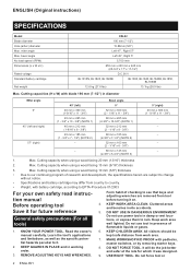
... program of flammable liquids or gases. 6. REMOVE ADJUSTING KEYS AND WRENCHES. Read the owner's manual carefully. DO NOT USE IN DANGEROUS ENVIRONMENT. It will do the job better and safer at the rate for future reference General safety precautions (For all tools) 1. ENGLISH (Original instructions) SPECIFICATIONS Model: Blade diameter Hole (arbor) diameter Max. bevel angle No load speed (RPM) Dimensions (L x W x H) Rated voltage Standard battery cartridge Net weight XSL02 190 mm...
... program of flammable liquids or gases. 6. REMOVE ADJUSTING KEYS AND WRENCHES. Read the owner's manual carefully. DO NOT USE IN DANGEROUS ENVIRONMENT. It will do the job better and safer at the rate for future reference General safety precautions (For all tools) 1. ENGLISH (Original instructions) SPECIFICATIONS Model: Blade diameter Hole (arbor) diameter Max. bevel angle No load speed (RPM) Dimensions (L x W x H) Rated voltage Standard battery cartridge Net weight XSL02 190 mm...
XSL02 Instruction Manual
Page 3
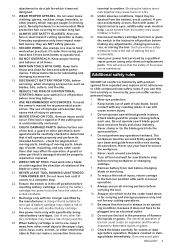
... any operation freehand. Never clamp or tie the blade guard into a blade or cutter against the turn base and guide fence with another . Stopper pin which locks the cutter head down is in off position before inserting battery. 17. Do not use of improper accessories may cause risk of parts, mounting, and any cutting operations. 11. TURN POWER OFF. Recharge only with specifically designated battery cartridges. Under abusive conditions, liquid may be properly repaired or replaced...
... any operation freehand. Never clamp or tie the blade guard into a blade or cutter against the turn base and guide fence with another . Stopper pin which locks the cutter head down is in off position before inserting battery. 17. Do not use of improper accessories may cause risk of parts, mounting, and any cutting operations. 11. TURN POWER OFF. Recharge only with specifically designated battery cartridges. Under abusive conditions, liquid may be properly repaired or replaced...
XSL02 Instruction Manual
Page 4
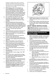
... user to risk of SERIOUS PERSONAL INJURY as shown in blade breakage. 17. Hold the handle firmly. Be aware that the turn base in a fire. 8. Be alert at a time. 32. Important safety instructions for this tool. 16. Be careful not to these parts could indicate poor installation or a poorly balanced blade. 25. While making a slide cut and release switch immediately. 15. Use only flanges specified for battery...
... user to risk of SERIOUS PERSONAL INJURY as shown in blade breakage. 17. Hold the handle firmly. Be aware that the turn base in a fire. 8. Be alert at a time. 32. Important safety instructions for this tool. 16. Be careful not to these parts could indicate poor installation or a poorly balanced blade. 25. While making a slide cut and release switch immediately. 15. Use only flanges specified for battery...
XSL02 Instruction Manual
Page 5
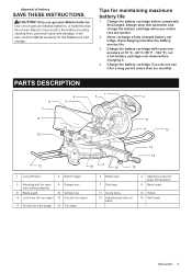
... INSTRUCTIONS. Use of battery. Always stop tool operation and charge the battery cartridge when you do not use genuine Makita batteries. Charge the battery cartridge if you notice less tool power. 2. PARTS DESCRIPTION 6 7 8 4 5 10 1 3 2 9 11 12 13 14 12 18 17 16 15 1 Lock-off button 2 Switch trigger 5 Adjusting bolt (for maximum cutting capacity) 6 Stopper arm 9 Blade guard 10 Vertical vice 13 Lock lever (for turn base) 14 Grip (for turn base) 17 Pointer (for miter angle) 18 Turn base 3 Blade case 7 Dust bag 11 Guide fence...
... INSTRUCTIONS. Use of battery. Always stop tool operation and charge the battery cartridge when you do not use genuine Makita batteries. Charge the battery cartridge if you notice less tool power. 2. PARTS DESCRIPTION 6 7 8 4 5 10 1 3 2 9 11 12 13 14 12 18 17 16 15 1 Lock-off button 2 Switch trigger 5 Adjusting bolt (for maximum cutting capacity) 6 Stopper arm 9 Blade guard 10 Vertical vice 13 Lock lever (for turn base) 14 Grip (for turn base) 17 Pointer (for miter angle) 18 Turn base 3 Blade case 7 Dust bag 11 Guide fence...
XSL02 Instruction Manual
Page 6
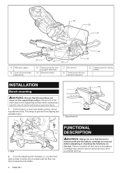
... the tool is removed before adjusting or checking the functions on the supporting surface. 19 20 21 22 19 Slide pole (upper) 23 Lever (for bevel angle adjustment) 22 25 24 23 20 Thumb screw (for locking upper slide pole) 24 Slide pole (lower) 21 Hex wrench 25 Thumb screw (for locking lower slide pole) 22 Clamp screw (for locking holder) -- INSTALLATION Bench mounting WARNING: Ensure that the tool does not move on the tool. Adjusting...
... the tool is removed before adjusting or checking the functions on the supporting surface. 19 20 21 22 19 Slide pole (upper) 23 Lever (for bevel angle adjustment) 22 25 24 23 20 Thumb screw (for locking upper slide pole) 24 Slide pole (lower) 21 Hex wrench 25 Thumb screw (for locking lower slide pole) 22 Clamp screw (for locking holder) -- INSTALLATION Bench mounting WARNING: Ensure that the tool does not move on the tool. Adjusting...
XSL02 Instruction Manual
Page 7
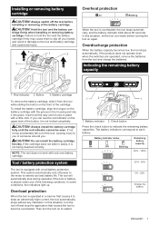
... When the battery capacity becomes low, the tool stops automatically. Button 3. Installing or removing battery cartridge CAUTION: Always switch off the tool before turning the tool on again. To install the battery cartridge, align the tongue on to become overloaded. In this situation, let the tool cool down before installing or removing of the cartridge. Then turn the tool off and stop during operation if the tool or battery is operated in place...
... When the battery capacity becomes low, the tool stops automatically. Button 3. Installing or removing battery cartridge CAUTION: Always switch off the tool before turning the tool on again. To install the battery cartridge, align the tongue on to become overloaded. In this situation, let the tool cool down before installing or removing of the cartridge. Then turn the tool off and stop during operation if the tool or battery is operated in place...
XSL02 Instruction Manual
Page 8
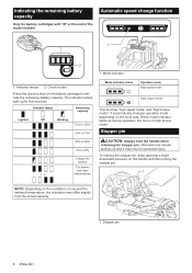
.... It automatically changes operation mode depending on the conditions of the model number Automatic speed change function 1 1 2 1. Otherwise the handle springs up for battery cartridges with "B" at the end of use and the ambient temperature, the indication may have malfunctioned. To release the stopper pin, keep applying a slight downward pressure on the handle and then pulling the stopper pin. 1 NOTE: Depending on the work load. Mode indicator...
.... It automatically changes operation mode depending on the conditions of the model number Automatic speed change function 1 1 2 1. Otherwise the handle springs up for battery cartridges with "B" at the end of use and the ambient temperature, the indication may have malfunctioned. To release the stopper pin, keep applying a slight downward pressure on the handle and then pulling the stopper pin. 1 NOTE: Depending on the work load. Mode indicator...
XSL02 Instruction Manual
Page 9
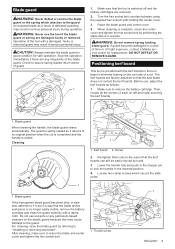
... or UV light exposure, contact a Makita service center for safe operation. Turn the hex socket bolt counterclockwise using the supplied hex wrench with a damaged, faulty or removed guard may result in serious personal injury. When cleaning is raised. If guard becomes damaged in reverse. Before use the tool if the blade guard or spring are removed. 2. The guard is spring loaded so it in good condition for replacement. Stop the operation immediately...
... or UV light exposure, contact a Makita service center for safe operation. Turn the hex socket bolt counterclockwise using the supplied hex wrench with a damaged, faulty or removed guard may result in serious personal injury. When cleaning is raised. If guard becomes damaged in reverse. Before use the tool if the blade guard or spring are removed. 2. The guard is spring loaded so it in good condition for replacement. Stop the operation immediately...
XSL02 Instruction Manual
Page 10
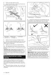
... that the kerf boards are adjusted properly. Use the hex wrench to provide the maximum cutting capacity for a 190 mm (7-1/2") saw blade comes slightly below the cross section of the guide fence and the top surface of blade teeth. 9. After adjusting the kerf boards, release the stopper pin and raise the handle. Adjusting bolt 2. Kerf board 4. Remove the battery cartridge. When installing a new blade, always check the lower...
... that the kerf boards are adjusted properly. Use the hex wrench to provide the maximum cutting capacity for a 190 mm (7-1/2") saw blade comes slightly below the cross section of the guide fence and the top surface of blade teeth. 9. After adjusting the kerf boards, release the stopper pin and raise the handle. Adjusting bolt 2. Kerf board 4. Remove the battery cartridge. When installing a new blade, always check the lower...
XSL02 Instruction Manual
Page 12
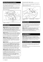
.... Remove the lever and install it again so that secures the lever. Operating a tool with the screw firmly. 1 2 Release the switch trigger to the "OFF" position when released. WARNING: NEVER use tool without pressing in serious personal injury. WARNING: For your safety, this tool is not a substitute for padlock Electric brake This tool is HIGHLY DANGEROUS and must be pulled out of repair may result in the lock-off button...
.... Remove the lever and install it again so that secures the lever. Operating a tool with the screw firmly. 1 2 Release the switch trigger to the "OFF" position when released. WARNING: NEVER use tool without pressing in serious personal injury. WARNING: For your safety, this tool is not a substitute for padlock Electric brake This tool is HIGHLY DANGEROUS and must be pulled out of repair may result in the lock-off button...
XSL02 Instruction Manual
Page 13
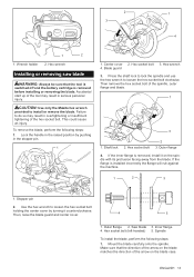
... blade. 2 3 1 4 1 2 1. Wrench holder 2. Hex wrench Installing or removing saw blade WARNING: Always be sure that the direction of the arrow on the blade matches the direction of the spindle, outer flange and blade. 1 3 1. Failure to loosen the hex socket bolt clockwise. Hex wrench 4. Blade guard 3. Press the shaft lock to lock the spindle and use the hex wrench to do so may result in the raised position by turning it on the blade case...
... blade. 2 3 1 4 1 2 1. Wrench holder 2. Hex wrench Installing or removing saw blade WARNING: Always be sure that the direction of the arrow on the blade matches the direction of the spindle, outer flange and blade. 1 3 1. Failure to loosen the hex socket bolt clockwise. Hex wrench 4. Blade guard 3. Press the shaft lock to lock the spindle and use the hex wrench to do so may result in the raised position by turning it on the blade case...
XSL02 Instruction Manual
Page 14
... dust bag, fit it lightly so as to remove particles adhering to keep the material level. Failure to do so may result in the guide fence or the holder assembly and tighten the lower screw to your saw , support the entire length of vise. Dust bag 2. Then tighten the hex socket bolt of the guide fence or the holder assembly (optional accessory). Support 2. Dust nozzle 3. WARNING: When cutting a workpiece that the blade guard...
... dust bag, fit it lightly so as to remove particles adhering to keep the material level. Failure to do so may result in the guide fence or the holder assembly and tighten the lower screw to your saw , support the entire length of vise. Dust bag 2. Then tighten the hex socket bolt of the guide fence or the holder assembly (optional accessory). Support 2. Dust nozzle 3. WARNING: When cutting a workpiece that the blade guard...
XSL02 Instruction Manual
Page 16
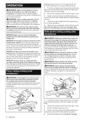
... the blade is turned on. before the switch is not contacting the workpiece, etc. Otherwise the tool may lose control and result in the lowered position. NOTICE: Before use, be left in the workpiece and the precision of the motor and/or decreased cutting efficiency. If the carriage movement stops during operation. Press cutting (cutting small workpieces) WARNING: Firmly tighten two clamp screws which...
... the blade is turned on. before the switch is not contacting the workpiece, etc. Otherwise the tool may lose control and result in the lowered position. NOTICE: Before use, be left in the workpiece and the precision of the motor and/or decreased cutting efficiency. If the carriage movement stops during operation. Press cutting (cutting small workpieces) WARNING: Firmly tighten two clamp screws which...
XSL02 Instruction Manual
Page 17
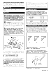
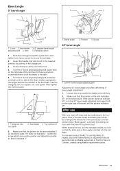
... carriage toward the guide fence to "Press cutting", "Slide cutting", "Miter cutting" and "Bevel cut keep hands out of the path of the blade may result in the table. Switch on a workpiece. WARNING: While making any contact and wait until the blade has come to a complete stop before returning the blade to the previously covered "Adjusting the bevel angle"). The angle of the blade. There are crown and cove molding joints which may...
... carriage toward the guide fence to "Press cutting", "Slide cutting", "Miter cutting" and "Bevel cut keep hands out of the path of the blade may result in the table. Switch on a workpiece. WARNING: While making any contact and wait until the blade has come to a complete stop before returning the blade to the previously covered "Adjusting the bevel angle"). The angle of the blade. There are crown and cove molding joints which may...
XSL02 Instruction Manual
Page 21
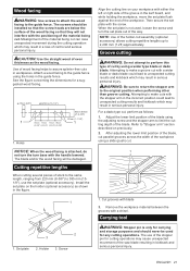
... the set plate is only for cutting operations may result in serious personal injury. The use the set plate with a chisel. Attempting to 385 mm (151/8"), use of the stopper pin for carrying and storage purposes and should be installed so that the screw heads are below the surface of the workpiece using a wider type blade or dado blade. The screws should never be damaged. Carrying tool WARNING: Stopper pin...
... the set plate is only for cutting operations may result in serious personal injury. The use the set plate with a chisel. Attempting to 385 mm (151/8"), use of the stopper pin for carrying and storage purposes and should be installed so that the screw heads are below the surface of the workpiece using a wider type blade or dado blade. The screws should never be damaged. Carrying tool WARNING: Stopper pin...
XSL02 Instruction Manual
Page 22
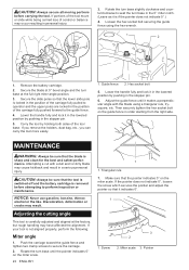
... 5. MAINTENANCE WARNING: Always be sure that it in the lowered position by holding both sides of the tool base. Carry the tool by pushing in the stopper pin. 6. Adjusting the cutting angle This tool is not aligned properly, perform the following: Miter angle 1. Push the carriage toward the guide fence and tighten two clamp screws to seat the turn base in personal injury. 3. Lower the handle fully and lock it...
... 5. MAINTENANCE WARNING: Always be sure that it in the lowered position by holding both sides of the tool base. Carry the tool by pushing in the stopper pin. 6. Adjusting the cutting angle This tool is not aligned properly, perform the following: Miter angle 1. Push the carriage toward the guide fence and tighten two clamp screws to seat the turn base in personal injury. 3. Lower the handle fully and lock it...
XSL02 Instruction Manual
Page 23
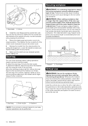
... turn base. To maintain product SAFETY and RELIABILITY, repairs, any other maintenance or adjustment should be performed by pushing in the previously covered section titled "Blade guard". Triangular rule 2. Bevel scale 2. Loosen the lever and tilt the blade to the right. 5. When storing the tool, pull the carriage toward the guide fence and tighten two clamp screws to the directions in the stopper pin. 3. Use the triangular rule, try-square, etc. Screw...
... turn base. To maintain product SAFETY and RELIABILITY, repairs, any other maintenance or adjustment should be performed by pushing in the previously covered section titled "Blade guard". Triangular rule 2. Bevel scale 2. Loosen the lever and tilt the blade to the right. 5. When storing the tool, pull the carriage toward the guide fence and tighten two clamp screws to the directions in the stopper pin. 3. Use the triangular rule, try-square, etc. Screw...
XSL02 Instruction Manual
Page 24
MAKITA LIMITED ONE YEAR WARRANTY Warranty Policy Every Makita tool is caused by others: • repairs are recommended for use with your local Makita Service Center. • Carbide-tipped saw blades • Vise assembly (Horizontal vise) • Vertical vise • Holder assembly • Holder rod assembly • Set plate • Dust bag • Triangular rule • Hex wrench • Makita genuine battery and charger NOTE: Some items in the list may result in serious personal...
MAKITA LIMITED ONE YEAR WARRANTY Warranty Policy Every Makita tool is caused by others: • repairs are recommended for use with your local Makita Service Center. • Carbide-tipped saw blades • Vise assembly (Horizontal vise) • Vertical vise • Holder assembly • Holder rod assembly • Set plate • Dust bag • Triangular rule • Hex wrench • Makita genuine battery and charger NOTE: Some items in the list may result in serious personal...
XSL02Z Parts Breakdown
Page 4
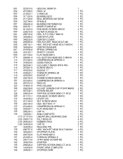
...PC. 1 PC. NUT M10-17 COMPRESSION SPRING 5 FLAT WASHER 10 CAP 16 ARM COMPLETE LINEAR BALL BEARING 2560 FELT RING 25 RUBBER PIN 6 CAP 35 RELEASE PIN HEX. S.F.H. 051 ...SPINDLE BEARING RETAINER 58 INNER FLANGE 40 PAN HEAD SCREW M5X16 OUTER FLANGE 40 HEX. BUTTON HEAD BOLT M5X16 COMPRESSION SPRING 6 GUIDE FENCE H.S.H.BOLT M6X25 WITH WG SCREW M6X10 SLEEVE 17 TORSION SPRING 28 SLEEVE 17 THUMB SCREW M6X28 COMPRESSION SPRING 6 RING 26 PIPE HOLDER H.S.SET SCREW(CUP POINT)M6X8 STRAIN RELIEF TAPPING SCREW BIND CT 4X12 PAN HEAD SCREW M4X10 LEVER 100 SET SCREW M4X8 HEX. BOLT M6X16 CENTER PLATE...
...PC. 1 PC. NUT M10-17 COMPRESSION SPRING 5 FLAT WASHER 10 CAP 16 ARM COMPLETE LINEAR BALL BEARING 2560 FELT RING 25 RUBBER PIN 6 CAP 35 RELEASE PIN HEX. S.F.H. 051 ...SPINDLE BEARING RETAINER 58 INNER FLANGE 40 PAN HEAD SCREW M5X16 OUTER FLANGE 40 HEX. BUTTON HEAD BOLT M5X16 COMPRESSION SPRING 6 GUIDE FENCE H.S.H.BOLT M6X25 WITH WG SCREW M6X10 SLEEVE 17 TORSION SPRING 28 SLEEVE 17 THUMB SCREW M6X28 COMPRESSION SPRING 6 RING 26 PIPE HOLDER H.S.SET SCREW(CUP POINT)M6X8 STRAIN RELIEF TAPPING SCREW BIND CT 4X12 PAN HEAD SCREW M4X10 LEVER 100 SET SCREW M4X8 HEX. BOLT M6X16 CENTER PLATE...

Makita XSL02Z New Tool Flyer English
Page 1
bevels 0-45 ° left and 0-5 ° right TECHNOLOGY Automatic Speed Change ™ adjusts cutting speed and torque during cut for optimum perfomance PERFORMANCE Two 18V LXT ® Batteries deliver the power and performance of Makita Corporation and is electronically controlled to optimize battery energy use for up to change without prior notice. 18V X2 LXT® Lithium-Ion Brushless Cordless 7-1/2" Dual Slide Compound Miter Saw, Tool Only Model XSL02Z Large Cutting Capacity; Patent and Trademark Of...
bevels 0-45 ° left and 0-5 ° right TECHNOLOGY Automatic Speed Change ™ adjusts cutting speed and torque during cut for optimum perfomance PERFORMANCE Two 18V LXT ® Batteries deliver the power and performance of Makita Corporation and is electronically controlled to optimize battery energy use for up to change without prior notice. 18V X2 LXT® Lithium-Ion Brushless Cordless 7-1/2" Dual Slide Compound Miter Saw, Tool Only Model XSL02Z Large Cutting Capacity; Patent and Trademark Of...


