
Manual
Page 3
...all -metal case; flexible external antenna rod; power Off/On switch; and mini locking connector for lapel (LT), Headmic™ (LT/HM), or instrument (GT) applications • HT-1KU and BT-1KU transmitters feature LCD displays indicating selected Group, Channel, Audio Input Levels, and Battery level status; Diversity A/B ...• Front panel backlit LCD display indicates selected Group, Channel, RF signal strength meter; System Features 4W-1KU Receiver • Unsurpassed state-of-the-art PLL UHF performance with 120dB dynamic range and operation up /down buttons on application;
...all -metal case; flexible external antenna rod; power Off/On switch; and mini locking connector for lapel (LT), Headmic™ (LT/HM), or instrument (GT) applications • HT-1KU and BT-1KU transmitters feature LCD displays indicating selected Group, Channel, Audio Input Levels, and Battery level status; Diversity A/B ...• Front panel backlit LCD display indicates selected Group, Channel, RF signal strength meter; System Features 4W-1KU Receiver • Unsurpassed state-of-the-art PLL UHF performance with 120dB dynamic range and operation up /down buttons on application;
Manual
Page 7
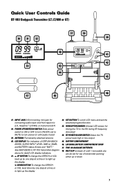
... 48. LCD DISPLAY For indication of transmitter pointing either up the display 42. See 30/31/32/33 in HT-1KU transmitter diagram above for connecting audio input cord from lapel mic (LT), Headmic™ (LT/HM), or instrument (GT) 38. SET BUTTON To scroll LCD menu and set to MUTE to light up... or down 7 BELT CLIP (on with audio muted 39. Quick User Controls Guide BT-1KU Bodypack Transmitter (LT, LT/HM or GT) 30 31 32 37 38 39 40 41 42 33 43 44 45 46 47 48 37. ANTENNA Permanently attached antenna...
... 48. LCD DISPLAY For indication of transmitter pointing either up the display 42. See 30/31/32/33 in HT-1KU transmitter diagram above for connecting audio input cord from lapel mic (LT), Headmic™ (LT/HM), or instrument (GT) 38. SET BUTTON To scroll LCD menu and set to MUTE to light up... or down 7 BELT CLIP (on with audio muted 39. Quick User Controls Guide BT-1KU Bodypack Transmitter (LT, LT/HM or GT) 30 31 32 37 38 39 40 41 42 33 43 44 45 46 47 48 37. ANTENNA Permanently attached antenna...

Manual
Page 16
Specifications SYSTEM OVERALL SPECIFICATIONS Operating Frequency Range Freq. Synthesized PLL System Frequency Stability Frequency Response Dynamic Range Harmonic Distortion Modulation Operating Range (U.S.) Band 1: 672.000-696.975MHz, (Int.) Band 2: 795.000-819.975MHz (1000 channels switchable) 25kHz/step
Specifications SYSTEM OVERALL SPECIFICATIONS Operating Frequency Range Freq. Synthesized PLL System Frequency Stability Frequency Response Dynamic Range Harmonic Distortion Modulation Operating Range (U.S.) Band 1: 672.000-696.975MHz, (Int.) Band 2: 795.000-819.975MHz (1000 channels switchable) 25kHz/step