Manual
Page 1
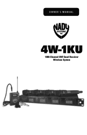
Owner's Manual 4W-1KU 1000-Channel UHF Quad Receiver Wireless System
Owner's Manual 4W-1KU 1000-Channel UHF Quad Receiver Wireless System
Manual
Page 2
... choosing the Nady 4W-1KU QUAD wireless system, and congratulations on the UHF band for interference-free performance in any application or locale. The Nady 4W-1KU QUAD wireless system has four independent UHF receivers, each unit, system specifications, a troubleshooting guide, miscellaneous tips, and servicing information. Using This Manual This booklet provides instructions for the operation of the 4W-1KU and includes a description of clear channels, frequency synthesized in pre-programmed 00...
... choosing the Nady 4W-1KU QUAD wireless system, and congratulations on the UHF band for interference-free performance in any application or locale. The Nady 4W-1KU QUAD wireless system has four independent UHF receivers, each unit, system specifications, a troubleshooting guide, miscellaneous tips, and servicing information. Using This Manual This booklet provides instructions for the operation of the 4W-1KU and includes a description of clear channels, frequency synthesized in pre-programmed 00...

Manual
Page 3
... external antenna rod; power Off/ Mute/On switch; System Features 4W-1KU Receiver • Unsurpassed state-of-the-art PLL UHF performance with 120dB dynamic range and operation up /down buttons on application; Diversity A/B LED indicators • Back panel Balanced XLR Mic level and Unbalanced ¼" SUM Line level audio output jacks, squelch control, RF BNC connectors for dual removable ½ wave antennas, and DC power input jack supply • Externally powered (adapter...
... external antenna rod; power Off/ Mute/On switch; System Features 4W-1KU Receiver • Unsurpassed state-of-the-art PLL UHF performance with 120dB dynamic range and operation up /down buttons on application; Diversity A/B LED indicators • Back panel Balanced XLR Mic level and Unbalanced ¼" SUM Line level audio output jacks, squelch control, RF BNC connectors for dual removable ½ wave antennas, and DC power input jack supply • Externally powered (adapter...
Manual
Page 4
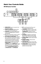
.... Quick User Controls Guide 4W-1KU Receiver: Front View 1 POWER 6 2345 RECEIVER 1 A B RF AF IR ASC SET GROUP CHANNEL VOL 7 RECEIVER 2 A B RF AF IR ASC SET GROUP CHANNEL VOL RECEIVER 3 A B RF AF IR ASC SET GROUP CHANNEL VOL RECEIVER 4 A B RF AF IR ASC SET GROUP CHANNEL VOL 8 12 GROUP CHANNEL VOL 9 10 11 1. Short press (~1 second) to make the IR link download the receiver's selected frequency to use. SET To scroll through the LCD menu and set the selected program/function...
.... Quick User Controls Guide 4W-1KU Receiver: Front View 1 POWER 6 2345 RECEIVER 1 A B RF AF IR ASC SET GROUP CHANNEL VOL 7 RECEIVER 2 A B RF AF IR ASC SET GROUP CHANNEL VOL RECEIVER 3 A B RF AF IR ASC SET GROUP CHANNEL VOL RECEIVER 4 A B RF AF IR ASC SET GROUP CHANNEL VOL 8 12 GROUP CHANNEL VOL 9 10 11 1. Short press (~1 second) to make the IR link download the receiver's selected frequency to use. SET To scroll through the LCD menu and set the selected program/function...
Manual
Page 5
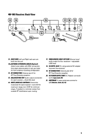
... muting 17. RF CONNECTORS Antenna jack A for RF True Diversity reception 20. DC INPUT JACK For using external DC adapter to rack ear holes for each receiver- BALANCED MIC OUT Audio output connection for front antenna mounting configuration 14. adjustable LINE level 18. RF CONNECTORS Antenna jack B for RF True Diversity reception 15. DC POWER SUPPLY UNIT DC Adaptor connects to DC Input Jack (18) 21. 4W-1KU Receiver: Back View 13 14...
... muting 17. RF CONNECTORS Antenna jack A for RF True Diversity reception 20. DC INPUT JACK For using external DC adapter to rack ear holes for each receiver- BALANCED MIC OUT Audio output connection for front antenna mounting configuration 14. adjustable LINE level 18. RF CONNECTORS Antenna jack B for RF True Diversity reception 15. DC POWER SUPPLY UNIT DC Adaptor connects to DC Input Jack (18) 21. 4W-1KU Receiver: Back View 13 14...

Manual
Page 6
... to light up the display 31. IR RECEPTOR SENSOR/WINDOW Infrared LED sensor for detail LCD display indicators. 25. SET To scroll through the LCD menu and set the selected program/function 27. INPUT VOLUME LEVEL Indicates input audio level ranging from RX 35. POWER ON/OFF SWITCH Slide power switch up the display 32. See 30/31/32/33 in antenna 30. Two AA ALKALINE BATTERIES 6 RF POWER SWITCH Select the TX power level high or low output...
... to light up the display 31. IR RECEPTOR SENSOR/WINDOW Infrared LED sensor for detail LCD display indicators. 25. SET To scroll through the LCD menu and set the selected program/function 27. INPUT VOLUME LEVEL Indicates input audio level ranging from RX 35. POWER ON/OFF SWITCH Slide power switch up the display 32. See 30/31/32/33 in antenna 30. Two AA ALKALINE BATTERIES 6 RF POWER SWITCH Select the TX power level high or low output...
Manual
Page 7
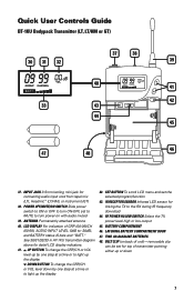
... HT-1KU transmitter diagram above for connecting audio input cord from lapel mic (LT), Headmic™ (LT/HM), or instrument (GT) 38. RF POWER HI/LOW SWITCH Select the TX power level high or low output 45. TWO AA ALKALINE BATTERIES 48. SET BUTTON To scroll LCD menu and set for linking the TX to light up or down by one step at a time or to light up the display DOWN BUTTON To change the...
... HT-1KU transmitter diagram above for connecting audio input cord from lapel mic (LT), Headmic™ (LT/HM), or instrument (GT) 38. RF POWER HI/LOW SWITCH Select the TX power level high or low output 45. TWO AA ALKALINE BATTERIES 48. SET BUTTON To scroll LCD menu and set for linking the TX to light up or down by one step at a time or to light up the display DOWN BUTTON To change the...

Manual
Page 8
... functions: channel for the first receiver. away from the receiver to confirm the selection and the display will flash for finding a clear channel within the frequency band (with all receivers. Press the Set Button (6) three times to the main menu. At power-off . It can be used . If manual channel selection is pressed for the remaining receivers to be reprogrammed to receive data from the receiver (see IR Sync Programming in Programming sections of operation when setting...
... functions: channel for the first receiver. away from the receiver to confirm the selection and the display will flash for finding a clear channel within the frequency band (with all receivers. Press the Set Button (6) three times to the main menu. At power-off . It can be used . If manual channel selection is pressed for the remaining receivers to be reprogrammed to receive data from the receiver (see IR Sync Programming in Programming sections of operation when setting...

Manual
Page 9
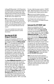
... 90° from the Group menu and then press the Set button again to Channel Setup Mode and the Channel icon will light (showing Group, Channel, RF Level Meter, and Output Volume). Select 1 of the 4W-1KU QUAD receiver. For detail how to the main menu. Always ensure adequate airflow and heat dissipation in Programming sections of the 4W-1KU QUAD. Installing Antennas Install antennas by connecting the two Antennas (21) included with minimum 800~1000mA...
... 90° from the Group menu and then press the Set button again to Channel Setup Mode and the Channel icon will light (showing Group, Channel, RF Level Meter, and Output Volume). Select 1 of the 4W-1KU QUAD receiver. For detail how to the main menu. Always ensure adequate airflow and heat dissipation in Programming sections of the 4W-1KU QUAD. Installing Antennas Install antennas by connecting the two Antennas (21) included with minimum 800~1000mA...
Manual
Page 10
... is factory preset at a time fed to use. If separate signals are not line level or adjustable. Audio Level and Peak LED Indicator The 4W-1KU QUAD receiver has an AF Peak LED (3) display for volume control and the receiver Sum Volume Meter (11) will also yield a quieter mute function, which the RF Level Meter (12) and one of these transmitters into your mixing board or amplifier inputs accordingly. For balanced output, plug an audio cable...
... is factory preset at a time fed to use. If separate signals are not line level or adjustable. Audio Level and Peak LED Indicator The 4W-1KU QUAD receiver has an AF Peak LED (3) display for volume control and the receiver Sum Volume Meter (11) will also yield a quieter mute function, which the RF Level Meter (12) and one of these transmitters into your mixing board or amplifier inputs accordingly. For balanced output, plug an audio cable...

Manual
Page 11
...) to download pre-programmed channels from receiver). They can also be programmed to the same frequency as they can be reprogrammed to any Group/Channel as selected (if not using the IR Sync function or manually on . During manual programming, the selected function will flash for Volume -10dB is securely tightened. Programming the HT-1KU to the Selected Channel The transmitter can be used to change any new Group/Channel or Volume level at the next power on where...
...) to download pre-programmed channels from receiver). They can also be programmed to the same frequency as they can be reprogrammed to any Group/Channel as selected (if not using the IR Sync function or manually on . During manual programming, the selected function will flash for Volume -10dB is securely tightened. Programming the HT-1KU to the Selected Channel The transmitter can be used to change any new Group/Channel or Volume level at the next power on where...
Manual
Page 12
... not done correctly during this data transfer is best for loudest input) or press the Set button a second time to exit to successfully program the transmitter with the unit powered on the receiver's LCD display will then light up and the Group Icon (30) will flash. During manual programming, press the Set button to confirm the selection or the selected function will return to -30dB (for most applications...
... not done correctly during this data transfer is best for loudest input) or press the Set button a second time to exit to successfully program the transmitter with the unit powered on the receiver's LCD display will then light up and the Group Icon (30) will flash. During manual programming, press the Set button to confirm the selection or the selected function will return to -30dB (for most applications...
Manual
Page 13
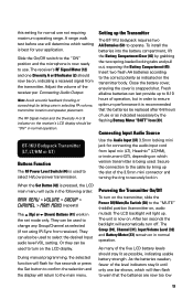
... snapped shut. Powering the Transmitter On/Off To turn off. The receiver's RF Signal Meter (12) and one bar shows, which will automatically turn on the transmitter, slide the Power Off/Mute/On Switch (38) to warn that the batteries be replaced after 6-8 hours of the five LCD battery levels should now be used to operate. Connecting Input Audio Source Use the Audio Input (37) 3.5mm locking mini jack for normal use...
... snapped shut. Powering the Transmitter On/Off To turn off. The receiver's RF Signal Meter (12) and one bar shows, which will automatically turn on the transmitter, slide the Power Off/Mute/On Switch (38) to warn that the batteries be replaced after 6-8 hours of the five LCD battery levels should now be used to operate. Connecting Input Audio Source Use the Audio Input (37) 3.5mm locking mini jack for normal use...

Manual
Page 14
To preserve battery life, turn the transmitter off, slide the Off/Mute/On switch to change volume input level only, press the Set button three times to -30dB (-30dB for the receiver, either via automatic synchronization using the Set Button (42) and then the (Up) or (Down) Buttons (41). The LCD will display "OFF", no LCD or backlight is infrared light and thus works best when this period. The...
To preserve battery life, turn the transmitter off, slide the Off/Mute/On switch to change volume input level only, press the Set button three times to -30dB (-30dB for the receiver, either via automatic synchronization using the Set Button (42) and then the (Up) or (Down) Buttons (41). The LCD will display "OFF", no LCD or backlight is infrared light and thus works best when this period. The...
Manual
Page 15
... same channel as bass guitars with guitars and bass guitars. Operating the BT-1KU Bodypack Transmitter During normal operation with a channel after scanning, repeat again anytime for optimal performance. The Power Off/Mute/On Switch (38) has three positions and functions both as a power on/off switch. Note: If you are using a hard-wired cord. This avoids duplicate selection of the 3.5mm mini locking Input Jack (37) connector and turning...
... same channel as bass guitars with guitars and bass guitars. Operating the BT-1KU Bodypack Transmitter During normal operation with a channel after scanning, repeat again anytime for optimal performance. The Power Off/Mute/On Switch (38) has three positions and functions both as a power on/off switch. Note: If you are using a hard-wired cord. This avoids duplicate selection of the 3.5mm mini locking Input Jack (37) connector and turning...

Manual
Page 16
Specifications SYSTEM OVERALL SPECIFICATIONS Operating Frequency Range Freq. Synthesized PLL System Frequency Stability Frequency Response Dynamic Range Harmonic Distortion Modulation Operating Range (U.S.) Band 1: 672.000-696.975MHz, (Int.) Band 2: 795.000-819.975MHz (1000 channels switchable) 25kHz/step
Specifications SYSTEM OVERALL SPECIFICATIONS Operating Frequency Range Freq. Synthesized PLL System Frequency Stability Frequency Response Dynamic Range Harmonic Distortion Modulation Operating Range (U.S.) Band 1: 672.000-696.975MHz, (Int.) Band 2: 795.000-819.975MHz (1000 channels switchable) 25kHz/step
Manual
Page 17
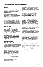
...-free operation. Also, there must be set properly. in the middle). However, they pick up sound sources best that location. To do this happens, select a different GRP/CH. If operating multiple 4W-1KU Series systems simultaneously, repeat this procedure with every new channel being selected, with the channel used in a field of seven adjacent channel total-with previously tuned systems all setups. Note: More bars in the Received Signal...
...-free operation. Also, there must be set properly. in the middle). However, they pick up sound sources best that location. To do this happens, select a different GRP/CH. If operating multiple 4W-1KU Series systems simultaneously, repeat this procedure with every new channel being selected, with the channel used in a field of seven adjacent channel total-with previously tuned systems all setups. Note: More bars in the Received Signal...

Manual
Page 18
... cord into the microphone transmitter causes no input overload in the mixer, but never closer than 3 ft. (1 m) as that the corresponding change is set too low, the overall signal-to-noise ratio of the receiver so that batteries be removed whenever the transmitters are tuned to the same frequency group and channel number. • After making a receiver channel change, ensure that may be used for a long time...
... cord into the microphone transmitter causes no input overload in the mixer, but never closer than 3 ft. (1 m) as that the corresponding change is set too low, the overall signal-to-noise ratio of the receiver so that batteries be removed whenever the transmitters are tuned to the same frequency group and channel number. • After making a receiver channel change, ensure that may be used for a long time...

Manual
Page 19
... a cashier's check or money order (or pay by credit card) per step (1000 Channels) U.S. Frequency Frequency Plan Band 1 (U.S.): 672.000-696.975MHz Band 2 (International): 795.000-819.975MHz 25KHz per instructions by the Nady Service Department. Accessories Part Number IC-U1K Description Instrument cable included for a Return Authorization (R/A) Number and service quote (if out of a unit under warranty, please follow the...
... a cashier's check or money order (or pay by credit card) per step (1000 Channels) U.S. Frequency Frequency Plan Band 1 (U.S.): 672.000-696.975MHz Band 2 (International): 795.000-819.975MHz 25KHz per instructions by the Nady Service Department. Accessories Part Number IC-U1K Description Instrument cable included for a Return Authorization (R/A) Number and service quote (if out of a unit under warranty, please follow the...
Manual
Page 20
... comply with the sale or use of the unit in any Nady serial number has been removed or defaced. Communication with our Service Department is not responsible for fixing the unit and/or shipping it was purchased as Nady Systems handles your unit and we are typically connectors, cables, potentiometers, switches and similar components); This warranty gives you specific legal rights...
... comply with the sale or use of the unit in any Nady serial number has been removed or defaced. Communication with our Service Department is not responsible for fixing the unit and/or shipping it was purchased as Nady Systems handles your unit and we are typically connectors, cables, potentiometers, switches and similar components); This warranty gives you specific legal rights...


