Manual
Page 2
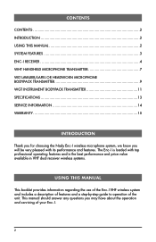
... features and a step‑by‑step guide to operation of your Enc-I. 2 CONTENTS CONTENTS ...2 INTRODUCTION 2 USING THIS MANUAL 2 SYSTEM FEATURES 3 ENC-I RECEIVER 4 WHT HANDHELD MICROPHONE TRANSMITTER 7 WLT LAVALIER/LAPEL OR HEADWORN MICROPHONE BODYPACK TRANSMITTER 9 WGT INSTRUMENT BODYPACK TRANSMITTER 11 SPECIFICATIONS 13 SERVICE INFORMATION 14 WARRANTY 15 INTRODUCTION Thank you for choosing the Nady Enc-I wireless microphone system, we know you may have about...
... features and a step‑by‑step guide to operation of your Enc-I. 2 CONTENTS CONTENTS ...2 INTRODUCTION 2 USING THIS MANUAL 2 SYSTEM FEATURES 3 ENC-I RECEIVER 4 WHT HANDHELD MICROPHONE TRANSMITTER 7 WLT LAVALIER/LAPEL OR HEADWORN MICROPHONE BODYPACK TRANSMITTER 9 WGT INSTRUMENT BODYPACK TRANSMITTER 11 SPECIFICATIONS 13 SERVICE INFORMATION 14 WARRANTY 15 INTRODUCTION Thank you for choosing the Nady Enc-I wireless microphone system, we know you may have about...
Manual
Page 3
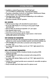
... cable • Easily accessible input level adjust control for unit "ON"; SYSTEM FEATURES • Available on site conditions) - lights steady for low battery alert WGT & WLT BODYPACK TRANSMITTERS • Choice of -sight • Noise-free transmitter ON-OFF operation ENC-I RECEIVER • Half-rack receiver design with retractable front panel antenna • RF and AF 5-LED displays for monitoring incoming signal strength and audio level • Balanced XLR and unbalanced adjustable 1/4" jack outputs...
... cable • Easily accessible input level adjust control for unit "ON"; SYSTEM FEATURES • Available on site conditions) - lights steady for low battery alert WGT & WLT BODYPACK TRANSMITTERS • Choice of -sight • Noise-free transmitter ON-OFF operation ENC-I RECEIVER • Half-rack receiver design with retractable front panel antenna • RF and AF 5-LED displays for monitoring incoming signal strength and audio level • Balanced XLR and unbalanced adjustable 1/4" jack outputs...
Manual
Page 4
...) between the receiver antenna and the transmitter at all times whenever possible. 4. Then plug the power supply into the DC INPUT JACK (11) on . Optimal antenna position is turned on the back of high heat - Side-by ‑side with a TELESCOPIC ANTENNA (16). Mute (Squelch) Adjustment In normal operation, the MUTE CONTROL (2) should be adjusted to the factory preset minimum RF level. This should be turned clockwise until...
...) between the receiver antenna and the transmitter at all times whenever possible. 4. Then plug the power supply into the DC INPUT JACK (11) on . Optimal antenna position is turned on the back of high heat - Side-by ‑side with a TELESCOPIC ANTENNA (16). Mute (Squelch) Adjustment In normal operation, the MUTE CONTROL (2) should be adjusted to the factory preset minimum RF level. This should be turned clockwise until...
Manual
Page 5
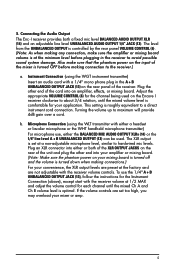
... XLR OUTPUT JACKS on the rear panel of the cord into an amplifier, effects, or mixing board. Plug the other end into either or both a fixed mic level BALANCED AUDIO OUTPUT XLR (14) and an adjustable line level UNBALANCED AUDIO OUTPUT 1/4" JACK (13). This setting is comfortable for your mixer or amp. 5 If the volume controls are not adjustable with the receiver volume at the minimum level before making any connection, make sure that the phantom power on...
... XLR OUTPUT JACKS on the rear panel of the cord into an amplifier, effects, or mixing board. Plug the other end into either or both a fixed mic level BALANCED AUDIO OUTPUT XLR (14) and an adjustable line level UNBALANCED AUDIO OUTPUT 1/4" JACK (13). This setting is comfortable for your mixer or amp. 5 If the volume controls are not adjustable with the receiver volume at the minimum level before making any connection, make sure that the phantom power on...

Manual
Page 6
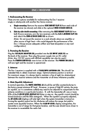
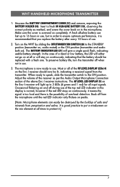
16 7 8 45 12-15V UNBALANCED OUT DC INPUT VOLUME BALANCED OUT MUTE 13 11 6 14 2 15 9 12 10 6 1 9 1 12
16 7 8 45 12-15V UNBALANCED OUT DC INPUT VOLUME BALANCED OUT MUTE 13 11 6 14 2 15 9 12 10 6 1 9 1 12
Manual
Page 7
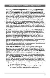
... the Audio Output Microphone Connection section of salts and minerals from the microphone until the red LED indicator only flickers on ). The BATTERY INDICATOR LED (21) will light up to protect it.] 7 Adjust the volume of the top red LED indicator in use . A fresh alkaline battery can easily be replaced with a fresh one. When ready to speak, slide the transmitter switch to the microphone. The microphone...
... the Audio Output Microphone Connection section of salts and minerals from the microphone until the red LED indicator only flickers on ). The BATTERY INDICATOR LED (21) will light up to protect it.] 7 Adjust the volume of the top red LED indicator in use . A fresh alkaline battery can easily be replaced with a fresh one. When ready to speak, slide the transmitter switch to the microphone. The microphone...

Manual
Page 9
... light up sound sources best that the battery should now be replaced with a 3.5 mm LOCKING JACK (24) for all times to protect it as straight as per the Audio Output Microphone Connection section of the mouth. (Note: The lavalier or headworn mic wire is about six inches usually works best. When ready to speak, slide the transmitter switch to the side of the front of the above Enc-I receiver instructions...
... light up sound sources best that the battery should now be replaced with a 3.5 mm LOCKING JACK (24) for all times to protect it as straight as per the Audio Output Microphone Connection section of the mouth. (Note: The lavalier or headworn mic wire is about six inches usually works best. When ready to speak, slide the transmitter switch to the side of the front of the above Enc-I receiver instructions...

Manual
Page 10
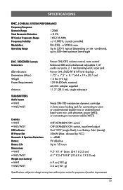
24 29 28 27 LOW MIC BAT HI OFF/STANDBY/ON 22 25 26 22 Opening Battery Compartment 23 10
24 29 28 27 LOW MIC BAT HI OFF/STANDBY/ON 22 25 26 22 Opening Battery Compartment 23 10
Manual
Page 11
... guitars/basses with dirty pots or connections are solid-this reason, the supplied INSTRUMENT CORD (35) has a factory installed capacitor inside the 1/4" plug. The BATTERY INDICATOR LED (33) will light up or shortening the cord may result. (Note: Scratchy noises can compromise the signal-to use of the RF signal from the transmitter. Adjust the volume of the receiver as per the Audio Output Instrument Connections section...
... guitars/basses with dirty pots or connections are solid-this reason, the supplied INSTRUMENT CORD (35) has a factory installed capacitor inside the 1/4" plug. The BATTERY INDICATOR LED (33) will light up or shortening the cord may result. (Note: Scratchy noises can compromise the signal-to use of the RF signal from the transmitter. Adjust the volume of the receiver as per the Audio Output Instrument Connections section...
Manual
Page 13
....4 X 6.1 X 2.0 cm) 6.9 oz (193 g) 3.6 oz (101 g) Specifications subject to change at any time without prior notice for connecting to 500+ feet optimum line-of product improvement 13 SPECIFICATIONS ENC-I RECEIVER Controls Connectors LED Indicators Dimensions (Max.) Weight Power Requirements Antenna Power ON/OFF, volume control, mute control Balanced XLR and unbalanced adjustable 1/4" audio out jacks, 2.1 mm barrel-type DC input jack Power ON, 5‑LED RF & AF level displays , 1.75" x 7.5" x 8.1" (4.4 x 19 x 20.7 cm) 1.6 lbs...
....4 X 6.1 X 2.0 cm) 6.9 oz (193 g) 3.6 oz (101 g) Specifications subject to change at any time without prior notice for connecting to 500+ feet optimum line-of product improvement 13 SPECIFICATIONS ENC-I RECEIVER Controls Connectors LED Indicators Dimensions (Max.) Weight Power Requirements Antenna Power ON/OFF, volume control, mute control Balanced XLR and unbalanced adjustable 1/4" audio out jacks, 2.1 mm barrel-type DC input jack Power ON, 5‑LED RF & AF level displays , 1.75" x 7.5" x 8.1" (4.4 x 19 x 20.7 cm) 1.6 lbs...
Manual
Page 14
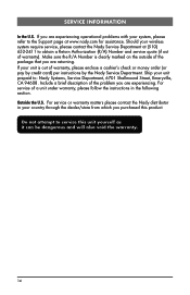
... wireless system require service, please contact the Nady Service Department at (510) 652-2411 to the Support page at www.nady.com for assistance. If you are experiencing operational problems with your unit prepaid to service this product. Ship your system, please refer to obtain a Return Authorization (R/A) Number and service quote (if out of the problem you are experiencing. SERVICE INFORMATION In...
... wireless system require service, please contact the Nady Service Department at (510) 652-2411 to the Support page at www.nady.com for assistance. If you are experiencing operational problems with your unit prepaid to service this product. Ship your system, please refer to obtain a Return Authorization (R/A) Number and service quote (if out of the problem you are experiencing. SERVICE INFORMATION In...

Manual
Page 15
... comply with the sale or use of merchantability and fitness are typically connectors, cables, potentiometers, switches and similar components); The warranty is required, please contact our Service Department at no representative or person including a Nady dealer, agent, or employee is discovered within the warranty period, Nady Systems, Inc. Communication with our Service Department is free from any Nady serial number has been...
... comply with the sale or use of merchantability and fitness are typically connectors, cables, potentiometers, switches and similar components); The warranty is required, please contact our Service Department at no representative or person including a Nady dealer, agent, or employee is discovered within the warranty period, Nady Systems, Inc. Communication with our Service Department is free from any Nady serial number has been...
Manual
Page 16
Operation is subject to the following two conditions: (1) this device may not cause harmful interference and (2) this device must accept any interference received, including interference that may cause undesired operation. 6701 Shellmound Street | Emeryville, CA USA 94608 T 510.652.2411 | F 510.652.5075 | www.nady.com The device complies with RSS-210 of Industry & Science Canada. Nady Wireless Systems are type accepted under FCC rules parts 90, 74 and 15.
Operation is subject to the following two conditions: (1) this device may not cause harmful interference and (2) this device must accept any interference received, including interference that may cause undesired operation. 6701 Shellmound Street | Emeryville, CA USA 94608 T 510.652.2411 | F 510.652.5075 | www.nady.com The device complies with RSS-210 of Industry & Science Canada. Nady Wireless Systems are type accepted under FCC rules parts 90, 74 and 15.


