

Interactive Instructions
Page 2
... 5: Adjusting the tilt (horizontal keystone 18 Installing the whiteboard...19 Installing the TouchBeam module...20 Step 1: Mounting the TouchBeam module 20 Step 2: Install Utility Software...22 Step 3: Initial Setup...23 Step 4: Operation Mode...24 Step 5: TouchBeam Alignment...25 Step 6: Touch Area Setting...28 Step 7: Calibration...30 Step 8: Touch Sensitivity...31 Step 9: Troubleshooting Viewer...32 Appendix...33 Troubleshooting...33 Interactive cable layout...38 Distance Calculator ...39 Specification...
... 5: Adjusting the tilt (horizontal keystone 18 Installing the whiteboard...19 Installing the TouchBeam module...20 Step 1: Mounting the TouchBeam module 20 Step 2: Install Utility Software...22 Step 3: Initial Setup...23 Step 4: Operation Mode...24 Step 5: TouchBeam Alignment...25 Step 6: Touch Area Setting...28 Step 7: Calibration...30 Step 8: Touch Sensitivity...31 Step 9: Troubleshooting Viewer...32 Appendix...33 Troubleshooting...33 Interactive cable layout...38 Distance Calculator ...39 Specification...

Interactive Instructions
Page 3
... on the projector receives infrared signals from the TouchBeam module which is required. Warning - Do not disassemble the TouchBeam module. Warning - How it works TouchBeam covers the entire whiteboard with dust blower. To operate normally: The IR camera should face the projection area of the whiteboard. Remove any obstacle in this user's manual. Warning - Usage Notice...
... on the projector receives infrared signals from the TouchBeam module which is required. Warning - Do not disassemble the TouchBeam module. Warning - How it works TouchBeam covers the entire whiteboard with dust blower. To operate normally: The IR camera should face the projection area of the whiteboard. Remove any obstacle in this user's manual. Warning - Usage Notice...

Interactive Instructions
Page 4
Package Overview TouchBeam module 2x (M2 6mm) screws 2x (M6 6mm) screws Interactive cable power cable 2x Alignment sticker sticjestickers TouchBeam bracket mounting plate Double sided tape TouchBeam mounting plate 5m USB cable 2x Passive pens CD user manual software 4
Package Overview TouchBeam module 2x (M2 6mm) screws 2x (M6 6mm) screws Interactive cable power cable 2x Alignment sticker sticjestickers TouchBeam bracket mounting plate Double sided tape TouchBeam mounting plate 5m USB cable 2x Passive pens CD user manual software 4

Interactive Instructions
Page 5
... florescent lights could interfere with the remote control of the mount in advance. the projected image is installed under the following conditions - the projector is tilted at an angle no more than 20 meters to reduce external noise We recommend using the interactive function install the projector so that the power supply and wiring work for the installation location of the projector We recommend to keep source cable...
... florescent lights could interfere with the remote control of the mount in advance. the projected image is installed under the following conditions - the projector is tilted at an angle no more than 20 meters to reduce external noise We recommend using the interactive function install the projector so that the power supply and wiring work for the installation location of the projector We recommend to keep source cable...

Interactive Instructions
Page 6
... the whiteboard Image area Image area 6 Mount the projector to the wall and attached the TouchBeam module to the wall 2. The screen surface is a flat, smooth surface with screws If the projection surface meets the criteria above, the projector and TouchBeam module can either be installed in one of more than 5mm. For details on how to check surface flatness...
... the whiteboard Image area Image area 6 Mount the projector to the wall and attached the TouchBeam module to the wall 2. The screen surface is a flat, smooth surface with screws If the projection surface meets the criteria above, the projector and TouchBeam module can either be installed in one of more than 5mm. For details on how to check surface flatness...

Interactive Instructions
Page 12
Installation guide Installation workflow o Install the projector mount (See mount installation guide) o Attach the projector to mount (See mount installation guide) o Connect sources to the projector o Adjust projected images (See mount installation guide) o Install the whiteboard (See whiteboard installation guide) o Install the TouchBeam module Attach to board Connect to projector / PC Calibrate Note: If the whiteboard is already installed please see page 36. 12
Installation guide Installation workflow o Install the projector mount (See mount installation guide) o Attach the projector to mount (See mount installation guide) o Connect sources to the projector o Adjust projected images (See mount installation guide) o Install the whiteboard (See whiteboard installation guide) o Install the TouchBeam module Attach to board Connect to projector / PC Calibrate Note: If the whiteboard is already installed please see page 36. 12

Interactive Instructions
Page 16
... caddy and fine adjuster together until the screen size is done. Fig 4D Adjust highlighted bolt to move the projector closer to the screen To increase the projected image size, loosen the bolt anticlockwise using one of the allen keys provided to fine adjust the throw distance - Fig 4E To reduce the projected image size, tighten the bolt clockwise using one of the...
... caddy and fine adjuster together until the screen size is done. Fig 4D Adjust highlighted bolt to move the projector closer to the screen To increase the projected image size, loosen the bolt anticlockwise using one of the allen keys provided to fine adjust the throw distance - Fig 4E To reduce the projected image size, tighten the bolt clockwise using one of the...

Interactive Instructions
Page 17
Fig 5C Adjust the highlighted thumbwheel to the required angle - Fig 5A Adjust the projector to fine adjust the tilt angle - Fig 5D To decrease the angle of projection, tighten the thumbwheel clockwise To increase the angle of the projector - Fig 5B Tighten the bolt to lock the angle of projection, loosen the thumbwheel anticlockwise 17 Step 5: Adjusting the tilt (vertical keystone) Loosen the single M8 x 75mm bolt -
Fig 5C Adjust the highlighted thumbwheel to the required angle - Fig 5A Adjust the projector to fine adjust the tilt angle - Fig 5D To decrease the angle of projection, tighten the thumbwheel clockwise To increase the angle of the projector - Fig 5B Tighten the bolt to lock the angle of projection, loosen the thumbwheel anticlockwise 17 Step 5: Adjusting the tilt (vertical keystone) Loosen the single M8 x 75mm bolt -

Interactive Instructions
Page 23
...; Core™ i3 or above 2GB or higher 110 MB 2. Operating system CPU Memory Min. System requirements To ensure normal operation of the software is shown in the table below describe the mode the software is set to: Touch mode Pen mode Disconnected 23 hard disk space System requirement Microsoft Windows XP (SP3)/Windows 7 (32bit/64bit)/Windows 8 (Must be installed. Step 2: Install Utility Software 1.
...; Core™ i3 or above 2GB or higher 110 MB 2. Operating system CPU Memory Min. System requirements To ensure normal operation of the software is shown in the table below describe the mode the software is set to: Touch mode Pen mode Disconnected 23 hard disk space System requirement Microsoft Windows XP (SP3)/Windows 7 (32bit/64bit)/Windows 8 (Must be installed. Step 2: Install Utility Software 1.
Interactive Instructions
Page 25
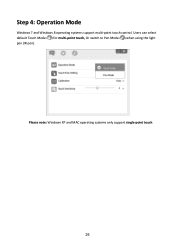
Step 4: Operation Mode Windows 7 and Windows 8 operating systems support multi-point touch control. Please note: Windows XP and MAC operating systems only support single-point touch 25 Users can select default Touch Mode ( ) for multi-point touch, Or switch to Pen Mode ( ) when using the light pen (IR pen).
Step 4: Operation Mode Windows 7 and Windows 8 operating systems support multi-point touch control. Please note: Windows XP and MAC operating systems only support single-point touch 25 Users can select default Touch Mode ( ) for multi-point touch, Or switch to Pen Mode ( ) when using the light pen (IR pen).

Interactive Instructions
Page 26
Press the button to switch to visible light mode (The Red LED will blink continuously) Mode IR Laser mode Visible light mode Error Blue LED Solid Solid -- LED indicator Red LED Description -- Rotate the black and grey adjustment knobs clockwise until they stop 26 Connect PC and Projector via USB cable 3. IR laser ON Blinking Visible light ON (IR Laser OFF, touch disabled) Solid Error of LD module occurred. 2. Step 5: TouchBeam Alignment 1.
Press the button to switch to visible light mode (The Red LED will blink continuously) Mode IR Laser mode Visible light mode Error Blue LED Solid Solid -- LED indicator Red LED Description -- Rotate the black and grey adjustment knobs clockwise until they stop 26 Connect PC and Projector via USB cable 3. IR laser ON Blinking Visible light ON (IR Laser OFF, touch disabled) Solid Error of LD module occurred. 2. Step 5: TouchBeam Alignment 1.

Interactive Instructions
Page 28
LED indicator Red LED Description -- Put top cover back on and tighten the screws. 28 Press the button again to switch back to IR mode (The Blue LED will stay solid) Mode IR Laser mode Visible light mode Error Blue LED Solid Solid -- IR laser ON Blinking Visible light ON (IR Laser OFF, touch disabled) Always ON Error of LD module occurred. 8. 7.
LED indicator Red LED Description -- Put top cover back on and tighten the screws. 28 Press the button again to switch back to IR mode (The Blue LED will stay solid) Mode IR Laser mode Visible light mode Error Blue LED Solid Solid -- IR laser ON Blinking Visible light ON (IR Laser OFF, touch disabled) Always ON Error of LD module occurred. 8. 7.

Interactive Instructions
Page 29
If not, adjust focus to sharpen the image If fail message pops up, switch to Manual Touch Area Setting. Select Manual Touch Area Setting: 29 B. Select Auto Touch Area Setting: Note: Quit all software applications Reduce ambient light Do not obstruct or shake lens during Touch Area Setting Check if projection image is clear. Step 6: Touch Area Setting A.
If not, adjust focus to sharpen the image If fail message pops up, switch to Manual Touch Area Setting. Select Manual Touch Area Setting: 29 B. Select Auto Touch Area Setting: Note: Quit all software applications Reduce ambient light Do not obstruct or shake lens during Touch Area Setting Check if projection image is clear. Step 6: Touch Area Setting A.

Interactive Instructions
Page 31
Select Manual Calibration: Note: Manual Calibration is clear. If not, adjust focus to sharpen the image If the Auto Calibration fail message still pops up , follow the steps shown below to Manual Calibration. Select Auto Calibration Note: If the fail message pops up on screen, switch to troubleshoot the issues. Close all software applications Reduce ambient light Do not obstruct or shake lens during calibration Check if projection image is suggested for better accuracy. 31 Step 7: Calibration A. B.
Select Manual Calibration: Note: Manual Calibration is clear. If not, adjust focus to sharpen the image If the Auto Calibration fail message still pops up , follow the steps shown below to Manual Calibration. Select Auto Calibration Note: If the fail message pops up on screen, switch to troubleshoot the issues. Close all software applications Reduce ambient light Do not obstruct or shake lens during calibration Check if projection image is suggested for better accuracy. 31 Step 7: Calibration A. B.

Interactive Instructions
Page 34
... USB port and check again. 3. The USB port of the laptop/PC manufacturer, and update the USB driver to Power Options in Control Panel, check USB selective suspend settings status in the USB cable and check again. 2. Restart your IT staff. 34 Unplug/re-plug in USB settings under Advance Settings. Switch to do when Windows system cannot identify the USB device? Use the USB cable included with your distributor. 7. Go to "Disabled". 5. If a USB extension is connected to BIOS setup...
... USB port and check again. 3. The USB port of the laptop/PC manufacturer, and update the USB driver to Power Options in Control Panel, check USB selective suspend settings status in the USB cable and check again. 2. Restart your IT staff. 34 Unplug/re-plug in USB settings under Advance Settings. Switch to do when Windows system cannot identify the USB device? Use the USB cable included with your distributor. 7. Go to "Disabled". 5. If a USB extension is connected to BIOS setup...

Interactive Instructions
Page 35
...? A: Red icon ( ) indicates a failed connection. Restart your projector and check again. Go to official website of the laptop/PC manufacturer, and update the BIOS driver to the latest version. 7. Use the USB cable included with your computer and check again. 4. A: 1. Unplug/re-plug in USB settings under Advance Settings. check USB selective suspend settings status in the USB cable and check again. 2. Go to official website of the laptop/PC manufacturer, and update the USB driver...
...? A: Red icon ( ) indicates a failed connection. Restart your projector and check again. Go to official website of the laptop/PC manufacturer, and update the BIOS driver to the latest version. 7. Use the USB cable included with your computer and check again. 4. A: 1. Unplug/re-plug in USB settings under Advance Settings. check USB selective suspend settings status in the USB cable and check again. 2. Go to official website of the laptop/PC manufacturer, and update the USB driver...

Interactive Instructions
Page 36
... and see Step 8 Calibration for troubleshooting. When Laptop/PC resolution is shown, this may result in Auto Calibration failure and Auto Touch Area Setting failure. Q6 What to do when Auto Calibration and Auto Touch Area Setting both fail? For better accuracy, please complete manual calibration. - A: Please perform Calibration and Touch Area setting during first installation. When the projectors OSD message is changed, calibrate again. - A: 1. Please wait...
... and see Step 8 Calibration for troubleshooting. When Laptop/PC resolution is shown, this may result in Auto Calibration failure and Auto Touch Area Setting failure. Q6 What to do when Auto Calibration and Auto Touch Area Setting both fail? For better accuracy, please complete manual calibration. - A: Please perform Calibration and Touch Area setting during first installation. When the projectors OSD message is changed, calibrate again. - A: 1. Please wait...

Interactive Instructions
Page 37
... light shown on screen again, please switch to Manual Mode to see Step 9 Touch Sensitivity for a certain projection area? If Touch function remains insensitive, please check the optical port condition. Please check Projector Display Mode selection. Adjust the level of both Auto Touch Area Setting and Auto Calibration. a. Do not obstruct or shake lens during Calibration d. Check if projection image is aligned. 4. If not, adjust focus to do when the mouse cursor ( ) flashes...
... light shown on screen again, please switch to Manual Mode to see Step 9 Touch Sensitivity for a certain projection area? If Touch function remains insensitive, please check the optical port condition. Please check Projector Display Mode selection. Adjust the level of both Auto Touch Area Setting and Auto Calibration. a. Do not obstruct or shake lens during Calibration d. Check if projection image is aligned. 4. If not, adjust focus to do when the mouse cursor ( ) flashes...
Interactive Instructions
Page 38
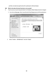
Q10 What to the setting page 2. Select "Smaller - 100%(Default) " and click "Apply". 38 particles are observed, gently clean the optical port with dust blower. A: Touch accuracy may be impacted when the Windows default display has been changed. 1. Go to do when the touch function is not accurate?
Q10 What to the setting page 2. Select "Smaller - 100%(Default) " and click "Apply". 38 particles are observed, gently clean the optical port with dust blower. A: Touch accuracy may be impacted when the Windows default display has been changed. 1. Go to do when the touch function is not accurate?

Interactive Instructions
Page 42
TouchBeam Touch Module Laser Safety Class 1 Curtain to Screen Distance LED Indicator 20mm ~ 100mm @75"~115" XGA/WXGA/1080p 40mm ~ 100mm @ 120"~140" 16:6 ultra-wide Blue/Red I . Specification I /O Port Interactive Jack x1 ID Size(W*L*H) Weight 150.0 (W) x 50.0 (L) x 40.0 (H) mm
TouchBeam Touch Module Laser Safety Class 1 Curtain to Screen Distance LED Indicator 20mm ~ 100mm @75"~115" XGA/WXGA/1080p 40mm ~ 100mm @ 120"~140" 16:6 ultra-wide Blue/Red I . Specification I /O Port Interactive Jack x1 ID Size(W*L*H) Weight 150.0 (W) x 50.0 (L) x 40.0 (H) mm


