
AGMX70 User Guide
Page 3
... and digital effects, this one unit. Connectors for connecting an external controller are added. Since its downstream keys, fade controls and audio mixers can also be used, the effects required for AB roll editing can also be synchronized. Overview This digital audio mixer is possible for the still, strobe and multi functions. Its dedicated software program, the MX-Navi, enables titles to be downloaded from...
... and digital effects, this one unit. Connectors for connecting an external controller are added. Since its downstream keys, fade controls and audio mixers can also be used, the effects required for AB roll editing can also be synchronized. Overview This digital audio mixer is possible for the still, strobe and multi functions. Its dedicated software program, the MX-Navi, enables titles to be downloaded from...
AGMX70 User Guide
Page 5
... down MX-Navi 80 Screen descriptions 80 Main window 80 Icon mode 80 List mode 82 Menu descriptions 83 File menu 83 Edit menu 83 View menu 84 Cursor menu 84 Operation menu 85 Tool menu 85 Help menu 85 Title data operations 86 Flow until Title data playback 86 Registering Title data in the transmission list ......... 86 Setting the Title data playback properties 86 Manual transmission and playback of Title data ..... 88 Automatic transmission...
... down MX-Navi 80 Screen descriptions 80 Main window 80 Icon mode 80 List mode 82 Menu descriptions 83 File menu 83 Edit menu 83 View menu 84 Cursor menu 84 Operation menu 85 Tool menu 85 Help menu 85 Title data operations 86 Flow until Title data playback 86 Registering Title data in the transmission list ......... 86 Setting the Title data playback properties 86 Manual transmission and playback of Title data ..... 88 Automatic transmission...
AGMX70 User Guide
Page 6
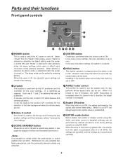
... is turned in the H direction, the width (horizontal) is used to set the aspect ratio for the selection of color settings, the color saturation is set to ON with a specific key pattern, it can be exited by manual operations even during the key position settings and the luminance setting Y among the color settings. 4 SCENE GRABBER button When this button is set . 3 Rotary Z control This control is used both ). Select "Power" from...
... is turned in the H direction, the width (horizontal) is used to set the aspect ratio for the selection of color settings, the color saturation is set to ON with a specific key pattern, it can be exited by manual operations even during the key position settings and the luminance setting Y among the color settings. 4 SCENE GRABBER button When this button is set . 3 Rotary Z control This control is used both ). Select "Power" from...
AGMX70 User Guide
Page 8
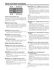
... adjustment and other video effects set by [Video Effects] to the preview connector. If both are to be output to the B/PRESET bus. When the button is performed as the image to be selected at the same time. When it is pressed together with keys, combined images can be displayed on the rear panel. 1 ME PRV selector button This button is used to...
... adjustment and other video effects set by [Video Effects] to the preview connector. If both are to be output to the B/PRESET bus. When the button is performed as the image to be selected at the same time. When it is pressed together with keys, combined images can be displayed on the rear panel. 1 ME PRV selector button This button is used to...
AGMX70 User Guide
Page 9
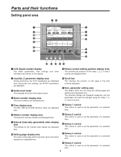
... item. > Rotary 3 control This control is displayed here. ? A SET UP INT VIDEO DSK FADE AUDIO EFFECTS @ B C D E> 1 LCD (liquid crystal) display The effect parameters, time settings and other information are shown on the page of a selected item. 6 Pattern number display area The transition and key numbers are displayed here. 7 Internal (internally generated) video display area The settings for the internal video signals are switched and displayed here. Rotary 4 control This control is used to set the parameter...
... item. > Rotary 3 control This control is displayed here. ? A SET UP INT VIDEO DSK FADE AUDIO EFFECTS @ B C D E> 1 LCD (liquid crystal) display The effect parameters, time settings and other information are shown on the page of a selected item. 6 Pattern number display area The transition and key numbers are displayed here. 7 Internal (internally generated) video display area The settings for the internal video signals are switched and displayed here. Rotary 4 control This control is used to set the parameter...
AGMX70 User Guide
Page 11
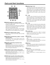
... headphone (PHONE) output. Since the audio meter displays the Prog output level, it can be monitored before fading so that it will remain unchanged even when the headphone level is changed. 2 TIME (time setting) rotary control This control is used to set the ME, DSK and FADE transition times. 3 PATTERN (transition/key pattern number setting) button Set this button to ON to set the time to be set the pattern numbers using the time setting rotary control. Parts and their...
... headphone (PHONE) output. Since the audio meter displays the Prog output level, it can be monitored before fading so that it will remain unchanged even when the headphone level is changed. 2 TIME (time setting) rotary control This control is used to set the ME, DSK and FADE transition times. 3 PATTERN (transition/key pattern number setting) button Set this button to ON to set the time to be set the pattern numbers using the time setting rotary control. Parts and their...
AGMX70 User Guide
Page 12
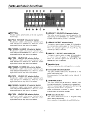
... internal video setting page for the B/PRESET bus. B/PRESET / INT/EXT selector button This button is used to select source 1 selected by the initial settings for the A/PROG bus. during fade-out, it is pressed together with the shift key, the external input (EXT) is selected. ; When it flashes. > AUTO TAKE button This button enables the ME transitions and keys to be transited automatically. Parts...
... internal video setting page for the B/PRESET bus. B/PRESET / INT/EXT selector button This button is used to select source 1 selected by the initial settings for the A/PROG bus. during fade-out, it is pressed together with the shift key, the external input (EXT) is selected. ; When it flashes. > AUTO TAKE button This button enables the ME transitions and keys to be transited automatically. Parts...
AGMX70 User Guide
Page 13
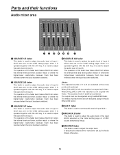
... with the shift key, it is used to adjust the audio level of input 5. The sounds of both A and B are selected at the cross points and combined. when it is operated together with Video. when it is operated together with Video. It executes the effects which have been set by Setup). 7 MASTER fader This fader is used to adjust the output level. The operation of the...
... with the shift key, it is used to adjust the audio level of input 5. The sounds of both A and B are selected at the cross points and combined. when it is operated together with Video. when it is operated together with Video. It executes the effects which have been set by Setup). 7 MASTER fader This fader is used to adjust the output level. The operation of the...
AGMX70 User Guide
Page 20
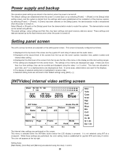
... video settings are performed on the [Setup] panel, the demonstration mode is established when the power is pressed. The panel settings, setup settings and their default settings using [Enter]. This menu is selected when the INTVideo button below the LCD display is turned on the [Setup] panel from the center down. The color set appears at a crosspoint. Setting panel screen The unit's various functions are adjusted on the display and the item setting ranges...
... video settings are performed on the [Setup] panel, the demonstration mode is established when the power is pressed. The panel settings, setup settings and their default settings using [Enter]. This menu is selected when the INTVideo button below the LCD display is turned on the [Setup] panel from the center down. The color set appears at a crosspoint. Setting panel screen The unit's various functions are adjusted on the display and the item setting ranges...
AGMX70 User Guide
Page 23
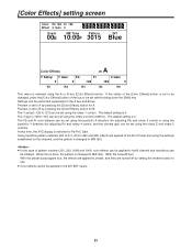
... [Color Effects] button for the A bus and B bus. The default setting is changed to MIX (56). ≥ In the case of pattern numbers 221, 222, 1068 and 1069, color effects can be applied to the B channel and transitions can be set using the joystick's Y direction (for adjusting Pb) and rotary 3 control or using the rotary 1 control. When this time, the XYZ display is changed to MIX...
... [Color Effects] button for the A bus and B bus. The default setting is changed to MIX (56). ≥ In the case of pattern numbers 221, 222, 1068 and 1069, color effects can be applied to the B channel and transitions can be set using the joystick's Y direction (for adjusting Pb) and rotary 3 control or using the rotary 1 control. When this time, the XYZ display is changed to MIX...
AGMX70 User Guide
Page 24
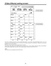
... bus to be performed separately for 3D. Video effects cannot be selected and set using the A or B bus [Video Effects] button. X 128 Y 128 Z 128 Event ME Time 00E 10:00F Pattern 3015 INT Blue Channel display Video Effects ch A Mosaic Size Off XY 0 Defocus Level Off 0 Mono Off Time Effects Screen Time Off Field 1 10F Decay Time Off 16 Paint Level Off 4 Nega Y C Off Off...
... bus to be performed separately for 3D. Video effects cannot be selected and set using the A or B bus [Video Effects] button. X 128 Y 128 Z 128 Event ME Time 00E 10:00F Pattern 3015 INT Blue Channel display Video Effects ch A Mosaic Size Off XY 0 Defocus Level Off 0 Mono Off Time Effects Screen Time Off Field 1 10F Decay Time Off 16 Paint Level Off 4 Nega Y C Off Off...
AGMX70 User Guide
Page 26
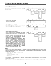
... cross point [Strobe] button with Video Effects ON using the rotary 5 control. The default setting is 20. The default setting is 1. Select the strobe time setting from 2 to take effect at the same time as a 2-dimensionally compressed pattern. Still and strobe (including multi strobe) cannot be changed in 2-step increments. At the Manual setting, the screen can be made to 124 using the rotary 2 control. ≥ When...
... cross point [Strobe] button with Video Effects ON using the rotary 5 control. The default setting is 20. The default setting is 1. Select the strobe time setting from 2 to take effect at the same time as a 2-dimensionally compressed pattern. Still and strobe (including multi strobe) cannot be changed in 2-step increments. At the Manual setting, the screen can be made to 124 using the rotary 2 control. ≥ When...
AGMX70 User Guide
Page 30
... time, and then press the Auto Take button. Fade 1) Preparation Perform the fade destination color and audio fade settings using the number keys. For fade-in step 2) and follow the same procedure. The A bus now becomes the background. 2) Input selection and preview Select the input source to be previewed at the Preview connector. 3) Pattern selection Select the pattern using the direct transition button or using...
... time, and then press the Auto Take button. Fade 1) Preparation Perform the fade destination color and audio fade settings using the number keys. For fade-in step 2) and follow the same procedure. The A bus now becomes the background. 2) Input selection and preview Select the input source to be previewed at the Preview connector. 3) Pattern selection Select the pattern using the direct transition button or using...
AGMX70 User Guide
Page 53
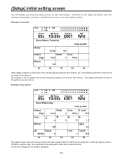
... part of the way through (by pressing other buttons, etc.), the settings performed so far will not be assigned to direct key pattern buttons. Example of transition Pos. The edges and effects of each effect pattern. [Setup] initial setting screen The LCD display now shows the setting screens for each of the patterns are the patterns displayed. 53 X 128 Y 128 Z 196 Event ME Time...
... part of the way through (by pressing other buttons, etc.), the settings performed so far will not be assigned to direct key pattern buttons. Example of transition Pos. The edges and effects of each effect pattern. [Setup] initial setting screen The LCD display now shows the setting screens for each of the patterns are the patterns displayed. 53 X 128 Y 128 Z 196 Event ME Time...
AGMX70 User Guide
Page 54
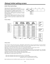
... press [Enter] to change to the setting mode. The lamp of S-2 for audio [Mic] or [AUX2] can be set : S-5 to S-8 + YC/Y Pb Pr/SDI Audio input combinations that the audio input is matched with different source numbers Example: SDI of S-1 for video and SDI of the selected button flashes, and the bus is selected using the rotary 3 control. Audio Input Video Setup When [Default] is automatically output to the default setting. Alternatively, select the...
... press [Enter] to change to the setting mode. The lamp of S-2 for audio [Mic] or [AUX2] can be set : S-5 to S-8 + YC/Y Pb Pr/SDI Audio input combinations that the audio input is matched with different source numbers Example: SDI of S-1 for video and SDI of the selected button flashes, and the bus is selected using the rotary 3 control. Audio Input Video Setup When [Default] is automatically output to the default setting. Alternatively, select the...
AGMX70 User Guide
Page 77
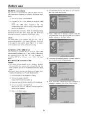
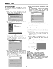
... the AG-MX70. Before use AG-MX70 connections It is not supplied with this unit. Insert the USB cable connectors into the corresponding USB ports on the PC and on the power to the PC. Use a commercially available 3 m or shorter USB cable. Check that Windows has started up. 3) Place the setup CD-ROM in "Installation of the USB driver It is necessary to install this driver in the PC to enable...
... the AG-MX70. Before use AG-MX70 connections It is not supplied with this unit. Insert the USB cable connectors into the corresponding USB ports on the PC and on the power to the PC. Use a commercially available 3 m or shorter USB cable. Check that Windows has started up. 3) Place the setup CD-ROM in "Installation of the USB driver It is necessary to install this driver in the PC to enable...
AGMX70 User Guide
Page 79
... "Next" button. Check that the power of the AGMX70 is shown, check the following procedure to the USB port of the USB cable must be switched on . 2) Select "Programs" > "Panasonic AG-MX70" > "MXNavi" from the "Start" menu. If "Not connecting" is switched on . ≥ The length of the PC. 79 from the Windows Start menu. To change the installation destination, click the "Browse" button, change the settings. 2) The setup start . 3) When the display column...
... "Next" button. Check that the power of the AGMX70 is shown, check the following procedure to the USB port of the USB cable must be switched on . 2) Select "Programs" > "Panasonic AG-MX70" > "MXNavi" from the "Start" menu. If "Not connecting" is switched on . ≥ The length of the PC. 79 from the Windows Start menu. To change the installation destination, click the "Browse" button, change the settings. 2) The setup start . 3) When the display column...
AGMX70 User Guide
Page 88
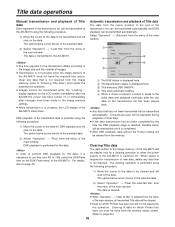
... image size and the number of images. ≥ Transmission is transmitted to page 90.) 88 display appears on the LCD screen immediately after the last data on the transmission list has been played back. ≥ Any data that is not required. Clear any data that is not required from the menu of the main window. The clearing operation is performed using the...
... image size and the number of images. ≥ Transmission is transmitted to page 90.) 88 display appears on the LCD screen immediately after the last data on the transmission list has been played back. ≥ Any data that is not required. Clear any data that is not required from the menu of the main window. The clearing operation is performed using the...
AGMX70 User Guide
Page 91
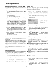
...-MX70 setup" from the menu of the memory status screen. display appears on the LCD screen immediately after the AG-MX70's power has been turned on the mixer setting window, and click the "Recall" button. Use the following procedure. 1) Select "Tools" > "Memory status" from the memory status screen menu. When the data to be read into the "Event Recall" column on or immediately after changes...
...-MX70 setup" from the menu of the memory status screen. display appears on the LCD screen immediately after the AG-MX70's power has been turned on the mixer setting window, and click the "Recall" button. Use the following procedure. 1) Select "Tools" > "Memory status" from the memory status screen menu. When the data to be read into the "Event Recall" column on or immediately after changes...
AGMX70 User Guide
Page 95
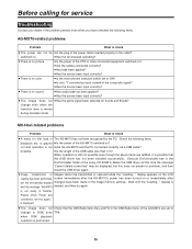
... switch set to change even when the transition lever is grayed ≥ Is the power of the setup CD-ROM to DSK even Title. possible. ≥ Is the length of the composite signal? ≥ Has the source been input correctly? ≥ There is displayed. ≥ The image does not Check that the USB driver has not been installed successfully. is no sound...
... switch set to change even when the transition lever is grayed ≥ Is the power of the setup CD-ROM to DSK even Title. possible. ≥ Is the length of the composite signal? ≥ Has the source been input correctly? ≥ There is displayed. ≥ The image does not Check that the USB driver has not been installed successfully. is no sound...


