
AJHD1400 User Guide
Page 5
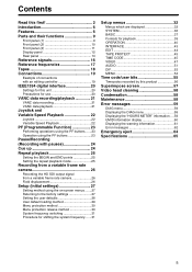
... frame rate camera 26 Recording the HD SDI output signal from a variable frame rate camera 26 Field displacement 26 Setup (initial settings 27 Setting method using the on-screen menus .......27 Returning to the factory settings 27 Setting the user defaults 28 User default loading method 29 Menu protection method 30 Menu protection release method 30 System frequency switching 31 Procedure for shifting the system frequency.......31 Setup menus 32 Menus which are displayed 32...
... frame rate camera 26 Recording the HD SDI output signal from a variable frame rate camera 26 Field displacement 26 Setup (initial settings 27 Setting method using the on-screen menus .......27 Returning to the factory settings 27 Setting the user defaults 28 User default loading method 29 Menu protection method 30 Menu protection release method 30 System frequency switching 31 Procedure for shifting the system frequency.......31 Setup menus 32 Menus which are displayed 32...
AJHD1400 User Guide
Page 6
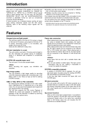
... not use DVCPRO HD cassettes. Introduction This unit is enabled by switching the setting on the system menu. z 720/50p over 60p sources can also play back tapes recorded using analog composite signals and SD SDI output. The compact size and light weight of 50 fps, the tape signals can be converted to DVCPRO HD-LP playback, the unit can be converted to conventional models. Features Compact size and light...
... not use DVCPRO HD cassettes. Introduction This unit is enabled by switching the setting on the system menu. z 720/50p over 60p sources can also play back tapes recorded using analog composite signals and SD SDI output. The compact size and light weight of 50 fps, the tape signals can be converted to DVCPRO HD-LP playback, the unit can be converted to conventional models. Features Compact size and light...
AJHD1400 User Guide
Page 7
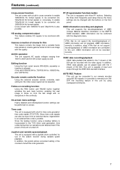
... power supply as well. HD analog component output This feature enables HD signals to our camera recorder using a backup battery is equipped with a joystick (stick controller) for film to an image with a built-in the continuity. UMID information recording and playback This unit supports the recording/playback of the unit is equipped with a built-in the TCG (time code generator), time codes during variable speed playback. AUTO REC Feature This unit can be connected...
... power supply as well. HD analog component output This feature enables HD signals to our camera recorder using a backup battery is equipped with a joystick (stick controller) for film to an image with a built-in the continuity. UMID information recording and playback This unit supports the recording/playback of the unit is equipped with a built-in the TCG (time code generator), time codes during variable speed playback. AUTO REC Feature This unit can be connected...
AJHD1400 User Guide
Page 8
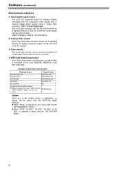
... monitored on the front DVCPRO HD panel. Features (continued) Multi-functional interfaces z Serial digital input/output The unit's HD component serial I/O interface enables interfacing with HD component video signals and 8channel digital audio signals using a single BNC connector. (SMPTE 292M/296M/299M) The unit is also equipped with the AV/ C command of the 9-pin REMOTE, REMOTE of HD SDI, IEEE1394. Playback format Output format DVCPRO HD-LP, DVCPRO HD DVCPRO HD, DVCPRO50, DV DVCPRO50 DVCPRO50, DV DVCPRO DVCPRO, DV DV, DVCAM...
... monitored on the front DVCPRO HD panel. Features (continued) Multi-functional interfaces z Serial digital input/output The unit's HD component serial I/O interface enables interfacing with HD component video signals and 8channel digital audio signals using a single BNC connector. (SMPTE 292M/296M/299M) The unit is also equipped with the AV/ C command of the 9-pin REMOTE, REMOTE of HD SDI, IEEE1394. Playback format Output format DVCPRO HD-LP, DVCPRO HD DVCPRO HD, DVCPRO50, DV DVCPRO50 DVCPRO50, DV DVCPRO DVCPRO, DV DV, DVCAM...

AJHD1400 User Guide
Page 9
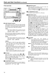
... is linked to enable recording. METER (FULL/FINE) selector button This button is always linked to control the unit using the REMOTE connector. REMOTE: Set to select the scale display for the audio level meter. LOCAL : Set to this position to the volume control knob. 9 In this state, the REC INH lamp lights on the HD SDI of the headphones is used to select the audio signals which are connected to the headset jack, you can be output...
... is linked to enable recording. METER (FULL/FINE) selector button This button is always linked to control the unit using the REMOTE connector. REMOTE: Set to select the scale display for the audio level meter. LOCAL : Set to this position to the volume control knob. 9 In this state, the REC INH lamp lights on the HD SDI of the headphones is used to select the audio signals which are connected to the headset jack, you can be output...
AJHD1400 User Guide
Page 10
... setting. Descriptions of power on the HOURS METER screen. VIDEO: Each time the VIDEO button is pressed, the input video signal selection is pressed together with the INPUT VIDEO switch on the front panel, the time code input to [1394] by remote control. Since the audio input signal at this button is switched in menu No. 005 SUPER. are canceled. When the button is pressed while holding down the PF button , the VTR information is restored. The deck's serial number, poweron time...
... setting. Descriptions of power on the HOURS METER screen. VIDEO: Each time the VIDEO button is pressed, the input video signal selection is pressed together with the INPUT VIDEO switch on the front panel, the time code input to [1394] by remote control. Since the audio input signal at this button is switched in menu No. 005 SUPER. are canceled. When the button is pressed while holding down the PF button , the VTR information is restored. The deck's serial number, poweron time...

AJHD1400 User Guide
Page 13
... replacement of the time code generator is reset if the backup battery voltage drops below the specified value. CTL: This area indicates the tape timer (control signal). UB: This area indicates user bit data. Green: This lights when the error rates for the video or audio playback level has increased. The playback picture and sound remain unaffected even while this lamp is lighted. The battery must be selected using menu...
... replacement of the time code generator is reset if the backup battery voltage drops below the specified value. CTL: This area indicates the tape timer (control signal). UB: This area indicates user bit data. Green: This lights when the error rates for the video or audio playback level has increased. The playback picture and sound remain unaffected even while this lamp is lighted. The battery must be selected using menu...
AJHD1400 User Guide
Page 14
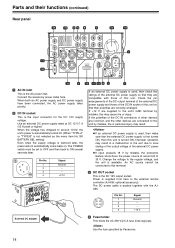
... connectors of the external DC power supply. An AC source cannot be set to OFF and then back to ON several seconds later. 1 2 3 4 Pin No. 1 2 3 4 Signal Ground - - +12 V External DC adapter If an external DC power supply is used , then make sure that the external DC power supply is first turned ON, then this unit is turned ON. If +12 V are correctly arranged. z If input exceeds 18 V by Panasonic. 14 Use the fuse...
... connectors of the external DC power supply. An AC source cannot be set to OFF and then back to ON several seconds later. 1 2 3 4 Pin No. 1 2 3 4 Signal Ground - - +12 V External DC adapter If an external DC power supply is used , then make sure that the external DC power supply is first turned ON, then this unit is turned ON. If +12 V are correctly arranged. z If input exceeds 18 V by Panasonic. 14 Use the fuse...
AJHD1400 User Guide
Page 15
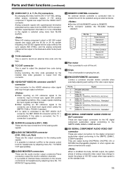
... RX (Y) REMOTE CONTROL PROTOCOL RECEIVE 15 REM TX (Y) REMOTE CONTROL PROTOCOL TRANSMIT HD SERIAL COMPONENT AUDIO VIDEO IN/ OUT connector These are output with positive and negative polarities. AUDIO OUT/MONITOR connector (CH1, CH2, Lch, Rch) These are output from the VIDEO OUT1 connector. REMOTE CONTROL connector An external remote controller is output from the VIDEO OUT2 connector. Pin No. z When inputting an SD reference signal to be operated using menu item No.005 SUPER. If the cable is connected, the 75 h connection is...
... RX (Y) REMOTE CONTROL PROTOCOL RECEIVE 15 REM TX (Y) REMOTE CONTROL PROTOCOL TRANSMIT HD SERIAL COMPONENT AUDIO VIDEO IN/ OUT connector These are output with positive and negative polarities. AUDIO OUT/MONITOR connector (CH1, CH2, Lch, Rch) These are output from the VIDEO OUT1 connector. REMOTE CONTROL connector An external remote controller is output from the VIDEO OUT2 connector. Pin No. z When inputting an SD reference signal to be operated using menu item No.005 SUPER. If the cable is connected, the 75 h connection is...
AJHD1400 User Guide
Page 20
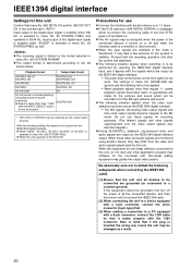
... signals other than "1394" DVCPRO HD* with the signals which will be selected as the output audio channel. z The AV signals may garble the output video picture. z The following setting, the signal is determined according to the list shown below. Non-linear editing equipment may be grounded, first turn the VTR's power off and when the interface cable is connected or disconnected. z The output format is not output from the video and audio signals...
... signals other than "1394" DVCPRO HD* with the signals which will be selected as the output audio channel. z The AV signals may garble the output video picture. z The following setting, the signal is determined according to the list shown below. Non-linear editing equipment may be grounded, first turn the VTR's power off and when the interface cable is connected or disconnected. z The output format is not output from the video and audio signals...
AJHD1400 User Guide
Page 26
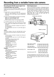
... rate camera to start recording. The following settings are as follows. Through the settings in menu No. 032 REC REF, the time code and the user bits recorded on the front panel: HDSDI 3 Change the mode for this unit to REC PAUSE mode. 4 Press the PAUSE button while confirming the HD SDI output image of this field, select "SLTC" in menu No. 032 REC REF when recording the HD SDI output signal...
... rate camera to start recording. The following settings are as follows. Through the settings in menu No. 032 REC REF, the time code and the user bits recorded on the front panel: HDSDI 3 Change the mode for this unit to REC PAUSE mode. 4 Press the PAUSE button while confirming the HD SDI output image of this field, select "SLTC" in menu No. 032 REC REF when recording the HD SDI output signal...

AJHD1400 User Guide
Page 28
... video monitor. The mode for major menu items is displayed in the counter display. SET-UP MENU ¢ NO FACTORY USER1(ALL) USER2(ALL) USER3(ALL) USER1(NOT SYSTEM) USER2(NOT SYSTEM) USER3(NOT SYSTEM) Setting the user defaults 1 Press the MENU button. z When the cursor is moved to "NO" and this unit will change to the default setting mode, and the default setting screen will return to the factory settings. z When storing a set...
... video monitor. The mode for major menu items is displayed in the counter display. SET-UP MENU ¢ NO FACTORY USER1(ALL) USER2(ALL) USER3(ALL) USER1(NOT SYSTEM) USER2(NOT SYSTEM) USER3(NOT SYSTEM) Setting the user defaults 1 Press the MENU button. z When the cursor is moved to "NO" and this unit will change to the default setting mode, and the default setting screen will return to the factory settings. z When storing a set...
AJHD1400 User Guide
Page 35
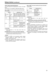
... and operations using the PF function, operations from the external encoder remote controller cannot be performed from both the external encoder remote controller and setup menus. Setup menus (continued) Video output signal adjustments The control matrix for IEEE1394 digital output. z Both the HD and SD can be accepted. External encoder remote controller/AJ-HD1400: Adjustments can be performed from both the external encoder remote controller and setup menus. External encoder remote controller/AJ-HD1400: Adjustments can be controlled at the same time...
... and operations using the PF function, operations from the external encoder remote controller cannot be performed from both the external encoder remote controller and setup menus. Setup menus (continued) Video output signal adjustments The control matrix for IEEE1394 digital output. z Both the HD and SD can be accepted. External encoder remote controller/AJ-HD1400: Adjustments can be performed from both the external encoder remote controller and setup menus. External encoder remote controller/AJ-HD1400: Adjustments can be controlled at the same time...
AJHD1400 User Guide
Page 38
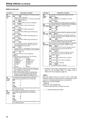
... are recommended. When the signal format to be output is set to other than DVCPRO HD and an external device is connected to the DV connector, the following displays appear for the modes. > DVCPRO HD-LP > DVCPRO_HD-LP DVCPRO HD > DVCPRO_HD DVCPRO50 > DVCPRO_50 DVCPRO > DVCPRO DV > DV DVCAM > DVCAM z When T&S&M is selected as the menu item No.022 PB FORMAT setting. 0000 HD_LP : The DVCPRO HD-LP format is selected...
... are recommended. When the signal format to be output is set to other than DVCPRO HD and an external device is connected to the DV connector, the following displays appear for the modes. > DVCPRO HD-LP > DVCPRO_HD-LP DVCPRO HD > DVCPRO_HD DVCPRO50 > DVCPRO_50 DVCPRO > DVCPRO DV > DV DVCAM > DVCAM z When T&S&M is selected as the menu item No.022 PB FORMAT setting. 0000 HD_LP : The DVCPRO HD-LP format is selected...
AJHD1400 User Guide
Page 39
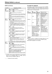
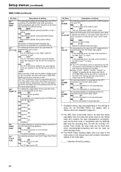
... the menu item No.023 FORMAL SEL setting. "_____" indicates the factory setting. 39 Setup menus (continued) BASIC (continued) No./Item Description of input. 031*1 OUT REF For selecting the video output reference. 0000 AUTO : The REF signal (HD/SD) which is input to the REF connector is automatically identified and serves as the reference. If neither the REF input signal nor HD serial input signal is supplied, the unit's internal...
... the menu item No.023 FORMAL SEL setting. "_____" indicates the factory setting. 39 Setup menus (continued) BASIC (continued) No./Item Description of input. 031*1 OUT REF For selecting the video output reference. 0000 AUTO : The REF signal (HD/SD) which is input to the REF connector is automatically identified and serves as the reference. If neither the REF input signal nor HD serial input signal is supplied, the unit's internal...

AJHD1400 User Guide
Page 45
... is used, or a DVCPRO HD/DVCPRO50/DVCPRO tape is used in the EE mode, any setting above : PRE is selected. 504*1 RUN MODE For setting the operation mode in which the internal time code generator runs. 0000 REC : The generator runs only while recording is in progress. 0001 FREE : The generator runs while the power is on regardless of the unit's operation mode. 505*1 TCG REGEN For setting the signal to...
... is used, or a DVCPRO HD/DVCPRO50/DVCPRO tape is used in the EE mode, any setting above : PRE is selected. 504*1 RUN MODE For setting the operation mode in which the internal time code generator runs. 0000 REC : The generator runs only while recording is in progress. 0001 FREE : The generator runs while the power is on regardless of the unit's operation mode. 505*1 TCG REGEN For setting the signal to...
AJHD1400 User Guide
Page 46
... : In the playback mode, the time code recorded in menu No. 25 SYSTEM FREQ. When selecting "1394" with the SMPTE/ EBU and the recording time. The LTC information and VITC information are supplied to IEEE1394 digital input/output connector is superimposed. *1 Displayed menus may not be read out when the tape stops. *B The VAUX (Video Auxiliary Data) area is established. z When "23/24," "25(HD)," "25(SD)," "50...
... : In the playback mode, the time code recorded in menu No. 25 SYSTEM FREQ. When selecting "1394" with the SMPTE/ EBU and the recording time. The LTC information and VITC information are supplied to IEEE1394 digital input/output connector is superimposed. *1 Displayed menus may not be read out when the tape stops. *B The VAUX (Video Auxiliary Data) area is established. z When "23/24," "25(HD)," "25(SD)," "50...
AJHD1400 User Guide
Page 53
... from an external device connected by the audio signals and menu No. 891 DIF DV AUDIO is set the value to reply with the format signal supporting the connected signal format and start the system. 894*1 HD > DIF OUT For selecting channels that are adjusted with the audio volume control on the front panel and displayed on . 883*1 DIF OUT CH For setting the output channel. 0000 0 : : 0063 63 The input channel is fixed...
... from an external device connected by the audio signals and menu No. 891 DIF DV AUDIO is set the value to reply with the format signal supporting the connected signal format and start the system. 894*1 HD > DIF OUT For selecting channels that are adjusted with the audio volume control on the front panel and displayed on . 883*1 DIF OUT CH For setting the output channel. 0000 0 : : 0063 63 The input channel is fixed...
AJHD1400 User Guide
Page 55
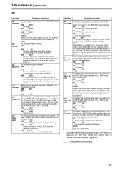
... the VIDEO MON connector. It enables operator numbers values to "EXT". (External time code selection) 4 The following steps. 1. Set the TCG switch to stop mode. 2 Select "TC" using the COUNTER button. 3 Set the TCG switch to be performed using menu No. 505 TCG REGEN. Time code/user bits Time code The time code is used for the time code generator using menu No. 504 RUN MODE. The VTR's playback speed can be selected with the video signal. FREE: When the power is on the display...
... the VIDEO MON connector. It enables operator numbers values to "EXT". (External time code selection) 4 The following steps. 1. Set the TCG switch to stop mode. 2 Select "TC" using the COUNTER button. 3 Set the TCG switch to be performed using menu No. 505 TCG REGEN. Time code/user bits Time code The time code is used for the time code generator using menu No. 504 RUN MODE. The VTR's playback speed can be selected with the video signal. FREE: When the power is on the display...
AJHD1400 User Guide
Page 65
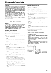
... mode) Tape timer accuracy: ±2 frames (when continuous CTL signal is used) (For slow replay at half speed or less, errors may occur in the CTL count.) [VIDEO] _Digital video Sampling frequency: Y: 74.25 MHz PB/PR: 37.125 MHz Quantizing: 8 bits Video compression system: DCT + variable length code Video compression ratio: 1:6.7 Error correction: Reed-Solomon product code Video recording bit rate: 100 Mbps _Video input connectors HD serial digital input...
... mode) Tape timer accuracy: ±2 frames (when continuous CTL signal is used) (For slow replay at half speed or less, errors may occur in the CTL count.) [VIDEO] _Digital video Sampling frequency: Y: 74.25 MHz PB/PR: 37.125 MHz Quantizing: 8 bits Video compression system: DCT + variable length code Video compression ratio: 1:6.7 Error correction: Reed-Solomon product code Video recording bit rate: 100 Mbps _Video input connectors HD serial digital input...


