
AKHBU931P User Guide
Page 3
...build-up unit's power from the monitor. ≥ Maintenance Disconnect the optical fiber cable plug, and wipe the unitr with the AK-HC931P multi-format camera. Caution ≥ Avoid using benzine, paint thinners or other volatile substances. ≥ If a chemically treated cloth is designed for its use the ...-up unit which is to be mounted, thus yielding the same range of at a distance of operations as that afforded by a larger camera. Dropping the viewfinder or subjecting it out well, and then wipe the unit gently. Operating precautions ≥ Be absolutely sure to turn ...
...build-up unit's power from the monitor. ≥ Maintenance Disconnect the optical fiber cable plug, and wipe the unitr with the AK-HC931P multi-format camera. Caution ≥ Avoid using benzine, paint thinners or other volatile substances. ≥ If a chemically treated cloth is designed for its use the ...-up unit which is to be mounted, thus yielding the same range of at a distance of operations as that afforded by a larger camera. Dropping the viewfinder or subjecting it out well, and then wipe the unit gently. Operating precautions ≥ Be absolutely sure to turn ...
AKHBU931P User Guide
Page 4
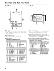
.... For details, refer to the operating instructions of the lens with the center groove, and attach. 2 Lens anchoring knob This is used to attach the camera. Signal Pin No. MODE (B) 10 EXT. Signal 1 BU ACTIVE 11 MONITOR SIGNAL 2 ANALOG GND 12 MONITOR GND 3 RET-1 13 DC +5 V 4 RET-2... 14 DC +3.15 V 5 RET-3 15 DC +2.7 V 6 DIGITAL GND 16 IRIS CONTROL 7 CAMERA DATA 17 IRIS POSITION 8 CAMERA CONTROL 18 ZOOM POSITION 9 DC +12 V 19 FOCUS POSITION 10 POWER GND 20 IRIS AUTO/REMOTE 4 MODE (A) 9 EXT. Signal 19 N.C. 20 N.C. 21 ...
.... For details, refer to the operating instructions of the lens with the center groove, and attach. 2 Lens anchoring knob This is used to attach the camera. Signal Pin No. MODE (B) 10 EXT. Signal 1 BU ACTIVE 11 MONITOR SIGNAL 2 ANALOG GND 12 MONITOR GND 3 RET-1 13 DC +5 V 4 RET-2... 14 DC +3.15 V 5 RET-3 15 DC +2.7 V 6 DIGITAL GND 16 IRIS CONTROL 7 CAMERA DATA 17 IRIS POSITION 8 CAMERA CONTROL 18 ZOOM POSITION 9 DC +12 V 19 FOCUS POSITION 10 POWER GND 20 IRIS AUTO/REMOTE 4 MODE (A) 9 EXT. Signal 19 N.C. 20 N.C. 21 ...
AKHBU931P User Guide
Page 6
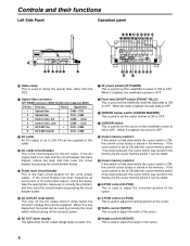
...turning off the AC output when it is lighted, the viewfinder's power is OFF. ; Function Polarity Signal flow 1 Optical fiber CAM#CCU 2 Optical fibe CCU#CAM 3 Control wire, hot + CAM!#CCU 4 Control wire, cold - If the cursor switch is set to ON after the cursor memory switch 1 has been pressed, the ... center marker to ON or OFF. 4 CURSOR switch This is used to set to ON or OFF. AC OUTLET reset switch This cuts off the camera's power. 8 V-POSI control [V-POSI] This is used to adjust the vertical position of the cursor. 9 Width control [WIDTH] This is used to adjust ...
...turning off the AC output when it is lighted, the viewfinder's power is OFF. ; Function Polarity Signal flow 1 Optical fiber CAM#CCU 2 Optical fibe CCU#CAM 3 Control wire, hot + CAM!#CCU 4 Control wire, cold - If the cursor switch is set to ON after the cursor memory switch 1 has been pressed, the ... center marker to ON or OFF. 4 CURSOR switch This is used to set to ON or OFF. AC OUTLET reset switch This cuts off the camera's power. 8 V-POSI control [V-POSI] This is used to adjust the vertical position of the cursor. 9 Width control [WIDTH] This is used to adjust ...
AKHBU931P User Guide
Page 7
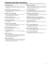
...switch [RET B] This is held down . It is effective when the LOCAL switch is used to E] These indicate the positions of RET A selected by the camera are output to select the picture-in-picture display position on the viewfinder screen. A CC filter indicators [A to select the RET B switch. K P in...to ON or OFF. F User switch [USER SEL] This enables control to be exercised over the ON/OFF status of RET B selected by the camera are output to the viewfinder. < 4:3 brightness modulation level control This is used to vary the brightness modulation level outside the 4:3 marker. H MONITOR...
...switch [RET B] This is held down . It is effective when the LOCAL switch is used to E] These indicate the positions of RET A selected by the camera are output to select the picture-in-picture display position on the viewfinder screen. A CC filter indicators [A to select the RET B switch. K P in...to ON or OFF. F User switch [USER SEL] This enables control to be exercised over the ON/OFF status of RET B selected by the camera are output to the viewfinder. < 4:3 brightness modulation level control This is used to vary the brightness modulation level outside the 4:3 marker. H MONITOR...
AKHBU931P User Guide
Page 8
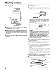
...methods Mounting the lens U-shaped groove Lens guide Mounting the camera 1 Mount the camera on the camera mounting base, and slide the camera toward the back to secure the camera. 6 Connect the camera connection optical fiber cable and interface cable to the camera. When the knob is rotated counterclockwise, it moves down.... of the arrow to return the pin to its original position after the camera has been detached, push the red lever again and simultaneously move the camera to the front. 4 Insert the camera's bayonet mount by aligning its position with the U-shaped groove in the front...
...methods Mounting the lens U-shaped groove Lens guide Mounting the camera 1 Mount the camera on the camera mounting base, and slide the camera toward the back to secure the camera. 6 Connect the camera connection optical fiber cable and interface cable to the camera. When the knob is rotated counterclockwise, it moves down.... of the arrow to return the pin to its original position after the camera has been detached, push the red lever again and simultaneously move the camera to the front. 4 Insert the camera's bayonet mount by aligning its position with the U-shaped groove in the front...
AKHBU931P User Guide
Page 9
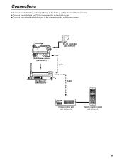
... Operation Panel AK-HRP930P Remote operation panel (AK-HRP931P) 9 Connections ≥ Connect the multi-format camera (and lens) to the build-up unit as shown in the figure below. ≥ Connect the cable from the CCU to the connector on the build-up unit. ≥ Connect the cable of the build-up... unit (AK-HBU931P) Cable CABLE OPEN SHORT ALARM FUSE 125V 5A FUSE 250V 2.5A TALLY/CALL MAIN HEAD POWER LEVEL COXN PGN1 PGN OFF PGN2 PUSH PRIVATE MIC ON OFF PTT Camera control...
... Operation Panel AK-HRP930P Remote operation panel (AK-HRP931P) 9 Connections ≥ Connect the multi-format camera (and lens) to the build-up unit as shown in the figure below. ≥ Connect the cable from the CCU to the connector on the build-up unit. ≥ Connect the cable of the build-up... unit (AK-HBU931P) Cable CABLE OPEN SHORT ALARM FUSE 125V 5A FUSE 250V 2.5A TALLY/CALL MAIN HEAD POWER LEVEL COXN PGN1 PGN OFF PGN2 PUSH PRIVATE MIC ON OFF PTT Camera control...


