

BTH1700 User Guide
Page 1
Printed in Japan VQT9586 P LCT1110-001A 1001-PN-I-U-VP Operating Instructions Model BT-H1700P ENGLISH VOLUME UNDER DEGAUSS SCAN PULSE CROSS COLOR OFF MENU SCREENS ASPECT AREA CHECK MARKER SLOT 1 SLOT 2 SLOT 3 A B C D E F INPUT SELECT POWER Multi-Format Monitor Before attempting to connect, operate or adjust this product, please read thess instructions completly.
Printed in Japan VQT9586 P LCT1110-001A 1001-PN-I-U-VP Operating Instructions Model BT-H1700P ENGLISH VOLUME UNDER DEGAUSS SCAN PULSE CROSS COLOR OFF MENU SCREENS ASPECT AREA CHECK MARKER SLOT 1 SLOT 2 SLOT 3 A B C D E F INPUT SELECT POWER Multi-Format Monitor Before attempting to connect, operate or adjust this product, please read thess instructions completly.
BTH1700 User Guide
Page 2
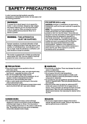
...shocks or vibrations. Never try to service it to malfunction. ● Do not block the ventilation slots. ● Do not expose this monitor without optional input cards. ● In these instructions, all the following precautions. FCC NOTICE (U.S.A. These may cause harmful interference to radio ...is operated in which case the user will be operated. There can generate picture noise and instability. ● Keep the monitor clean by PANASONIC could deform the cabinet or cause the performance of all explanations (except where noted) refer to the BT-H1700P with a ...
...shocks or vibrations. Never try to service it to malfunction. ● Do not block the ventilation slots. ● Do not expose this monitor without optional input cards. ● In these instructions, all the following precautions. FCC NOTICE (U.S.A. These may cause harmful interference to radio ...is operated in which case the user will be operated. There can generate picture noise and instability. ● Keep the monitor clean by PANASONIC could deform the cabinet or cause the performance of all explanations (except where noted) refer to the BT-H1700P with a ...
BTH1700 User Guide
Page 5
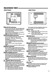
...screen is displayed. Buttons A through SLOT 3. C, D : select the picture from the SLOT 3 input card. Orange : The main power is ON, but the monitor's power is OFF (in the following order: Normal screen[Red screen[Green screen Blue screenp Press the SCREENS CHECK button when the blue screen is... to confirm the white balance. Input cards are installed. 26 Main power switch Press the switch to be installed in yellow and the monitor enters the stand-by closing the circuit (point of the current input signal is displayed (for correspondence between the input terminals and the INPUT...
...screen is displayed. Buttons A through SLOT 3. C, D : select the picture from the SLOT 3 input card. Orange : The main power is ON, but the monitor's power is OFF (in the following order: Normal screen[Red screen[Green screen Blue screenp Press the SCREENS CHECK button when the blue screen is... to confirm the white balance. Input cards are installed. 26 Main power switch Press the switch to be installed in yellow and the monitor enters the stand-by closing the circuit (point of the current input signal is displayed (for correspondence between the input terminals and the INPUT...
BTH1700 User Guide
Page 6
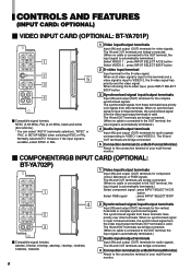
... video signal. The IN and OUT terminals are bridge-connected. 5 Connection terminal (to a Multi-Format Monitor) Attach to the connection terminal of your multi-format monitor. 6 The IN and OUT terminals are bridge-connected. (When no synchronised signal is input to the OUT... (G/Y terminals) is automatically terminated.) Select component signal : press INPUT SELECT A/C/E button Select RGB signal : press INPUT SELECT B/D/F button IN OUT HD/CS IN OUT VD 2 IN OUT AUDIO 3 IN OUT 4 2 Synchronised signal input/output terminals Input (IN) and output (OUT) terminals ...
... video signal. The IN and OUT terminals are bridge-connected. 5 Connection terminal (to a Multi-Format Monitor) Attach to the connection terminal of your multi-format monitor. 6 The IN and OUT terminals are bridge-connected. (When no synchronised signal is input to the OUT... (G/Y terminals) is automatically terminated.) Select component signal : press INPUT SELECT A/C/E button Select RGB signal : press INPUT SELECT B/D/F button IN OUT HD/CS IN OUT VD 2 IN OUT AUDIO 3 IN OUT 4 2 Synchronised signal input/output terminals Input (IN) and output (OUT) terminals ...
BTH1700 User Guide
Page 7
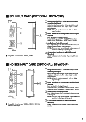
...if contained in the input digital signal. 4 Connection terminal (to a Multi-Format Monitor) Attach to the connection terminal of your multi-format monitor. 7 Select HD SDI 1 : press INPUT SELECT A/C/E button Select HD SDI 2 : press INPUT SELECT B/D/F button 3 Audio input/output terminals Input (IN...output (OUT) terminals for the analogue signals corresponding to the connection terminal of your multi-format monitor. Ⅵ HD SDI INPUT CARD (OPTIONAL: BT-YA704P) SWITCHED OUT 1 HD SDI 1 IN 2 4 IN HD SDI 2 AUDIO 3 IN OUT Ⅵ Compatible signal formats: 720/60p, 1035/60i, ...
...if contained in the input digital signal. 4 Connection terminal (to a Multi-Format Monitor) Attach to the connection terminal of your multi-format monitor. 7 Select HD SDI 1 : press INPUT SELECT A/C/E button Select HD SDI 2 : press INPUT SELECT B/D/F button 3 Audio input/output terminals Input (IN...output (OUT) terminals for the analogue signals corresponding to the connection terminal of your multi-format monitor. Ⅵ HD SDI INPUT CARD (OPTIONAL: BT-YA704P) SWITCHED OUT 1 HD SDI 1 IN 2 4 IN HD SDI 2 AUDIO 3 IN OUT Ⅵ Compatible signal formats: 720/60p, 1035/60i, ...
BTH1700 User Guide
Page 8
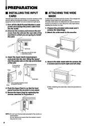
...8549; ATTACHING THE WIDE MASK A wide mask is mounted in a rack. Prepare the provided wide mask and 4 screws (for attaching). 2. Fit the board to the monitor or board pattern. Knob 3. PREPARATION Ⅵ INSTALLING THE INPUT CARD Optional input cards are not in use the functions of the BT-YA701P) Knob 4. Unscrew... rails. Insert the Input Card's board (greencoloured) into the slot, fitting the board into the guide rails on the rear side of the monitor) in reverse. Secure the Input Card by replacing the screws removed in Procedure 2. ● When detaching the wide mask, follow this...
...8549; ATTACHING THE WIDE MASK A wide mask is mounted in a rack. Prepare the provided wide mask and 4 screws (for attaching). 2. Fit the board to the monitor or board pattern. Knob 3. PREPARATION Ⅵ INSTALLING THE INPUT CARD Optional input cards are not in use the functions of the BT-YA701P) Knob 4. Unscrew... rails. Insert the Input Card's board (greencoloured) into the slot, fitting the board into the guide rails on the rear side of the monitor) in reverse. Secure the Input Card by replacing the screws removed in Procedure 2. ● When detaching the wide mask, follow this...
BTH1700 User Guide
Page 9
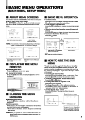
BASIC MENU OPERATIONS (MAIN MENU, SETUP MENU) ENGLISH Ⅵ ABOUT MENU SCREENS This monitor features a MAIN MENU (main menu screen) and a SETUP MENU (setup menu screen). STATUS DISPLAY CONTROL LOCK all reset" function, the Menu Screen does not disappear ...:+ SELECT: MAIN MENU (main menu screen) SETUP MENU (setup menu screen) NOTE : The contents of menus vary depending on the top or bottom of the monitor's settings. when setting "LOWER" in "sub menu POSITION" The lower dark screen; APERTURE CONTROL SLOT CONDITION sub menu POSITION :LOWER COLOR MATRIX SLOT CONDITION sub...
BASIC MENU OPERATIONS (MAIN MENU, SETUP MENU) ENGLISH Ⅵ ABOUT MENU SCREENS This monitor features a MAIN MENU (main menu screen) and a SETUP MENU (setup menu screen). STATUS DISPLAY CONTROL LOCK all reset" function, the Menu Screen does not disappear ...:+ SELECT: MAIN MENU (main menu screen) SETUP MENU (setup menu screen) NOTE : The contents of menus vary depending on the top or bottom of the monitor's settings. when setting "LOWER" in "sub menu POSITION" The lower dark screen; APERTURE CONTROL SLOT CONDITION sub menu POSITION :LOWER COLOR MATRIX SLOT CONDITION sub...
BTH1700 User Guide
Page 11
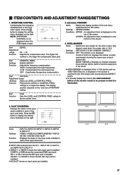
... : RGB : NO SLOT : NO SLOT EXIT: MENU Items Settings Function : INPUT A:/INPUT B:/INPUT C:/INPUT D:/INPUT E:/INPUT F: : VIDEO-1/VIDEO-2/COMPO./RGB/SDI 1/SDI 2/ HD SDI 1/HD SDI 2/NO SLOT : Displays the status of the input cards installed in each of the input cards installed in each aspect ratio. COMPO. SDI 1 or... the 16:9 screen ratio by pressing the ASPECT button. ● To actually display the marker, the AREA MARKER button on the monitor needs to display the setting menu illustrated on the screen. Press the button to be used when the screen ratio is displayed on the...
... : RGB : NO SLOT : NO SLOT EXIT: MENU Items Settings Function : INPUT A:/INPUT B:/INPUT C:/INPUT D:/INPUT E:/INPUT F: : VIDEO-1/VIDEO-2/COMPO./RGB/SDI 1/SDI 2/ HD SDI 1/HD SDI 2/NO SLOT : Displays the status of the input cards installed in each of the input cards installed in each aspect ratio. COMPO. SDI 1 or... the 16:9 screen ratio by pressing the ASPECT button. ● To actually display the marker, the AREA MARKER button on the monitor needs to display the setting menu illustrated on the screen. Press the button to be used when the screen ratio is displayed on the...
BTH1700 User Guide
Page 12
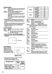
... be pressed so that it is 16:9. (for function expansion in a single-line display. Press the button to display the setting menu illustrated on the monitor needs to "ITU601" or "ITU709" depending on the "sub menu POSITION" setting. : Same as 1080i/1035i/720p etc. The factory preset of each marker is... setting. (No markers are displayed even if each aspect ratio. Settings : ON/OFF Functions : ON : The centre marker (a white cross) is selected only in the monitor's AREA MARKER-R setting.) 6. The display position depends on the input signal format. Centre marker 7.
... be pressed so that it is 16:9. (for function expansion in a single-line display. Press the button to display the setting menu illustrated on the monitor needs to "ITU601" or "ITU709" depending on the "sub menu POSITION" setting. : Same as 1080i/1035i/720p etc. The factory preset of each marker is... setting. (No markers are displayed even if each aspect ratio. Settings : ON/OFF Functions : ON : The centre marker (a white cross) is selected only in the monitor's AREA MARKER-R setting.) 6. The display position depends on the input signal format. Centre marker 7.
BTH1700 User Guide
Page 13
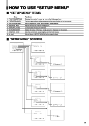
..." Ⅵ "SETUP MENU" ITEMS Items 1 FUNCTION SETTING 2 PICTURE SUB ADJ. 3 COLOR TEMP./BAL. 4 SIZE/POSI. Sets the control lock preventing the monitor from misuse. Sets all reset Functions Displays the monitor's power-up time or the total usage time. BLUE DRIVE RED DRIVE GREEN CUTOFF BLUE CUTOFF RED CUTOFF sub menu reset...
..." Ⅵ "SETUP MENU" ITEMS Items 1 FUNCTION SETTING 2 PICTURE SUB ADJ. 3 COLOR TEMP./BAL. 4 SIZE/POSI. Sets the control lock preventing the monitor from misuse. Sets all reset Functions Displays the monitor's power-up time or the total usage time. BLUE DRIVE RED DRIVE GREEN CUTOFF BLUE CUTOFF RED CUTOFF sub menu reset...
BTH1700 User Guide
Page 14
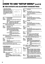
...SMPTE/B75/B00 Function : Sets the level of the colour density. SMPTE : Compliant with Betacam 7.5% set the PHASE knob on many multi-format monitors simultaneously, it returns to 0. NOTE : COMPO. LEVEL is displayed only when a 480/60i, 480/60p, 576/50i or 576/50p signal ...PHASE and COMPO. However, if the input signal is pressed. Before adjustment, set -up signal. FUNCTION SETTING Selects the colour system and displays the monitor's powerup time or the total usage time. Item : CONTRAST Adjustment range : -20 ~ 00 ~ +20 Function : For approximate adjustment of the ...
...SMPTE/B75/B00 Function : Sets the level of the colour density. SMPTE : Compliant with Betacam 7.5% set the PHASE knob on many multi-format monitors simultaneously, it returns to 0. NOTE : COMPO. LEVEL is displayed only when a 480/60i, 480/60p, 576/50i or 576/50p signal ...PHASE and COMPO. However, if the input signal is pressed. Before adjustment, set -up signal. FUNCTION SETTING Selects the colour system and displays the monitor's powerup time or the total usage time. Item : CONTRAST Adjustment range : -20 ~ 00 ~ +20 Function : For approximate adjustment of the ...
BTH1700 User Guide
Page 17
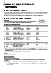
...on the remote control) setting. *3 : The STATUS function is activated when the connection to the STATUS terminal is the MAKE terminal, which controls the monitor by a PC via serial communication. Changing the Signal Input 1. Set REMOTE ENABLE to the ground (GND) terminal. Short-circuit the desired INPUT terminal....The functions of Terminals 10 9 8 54321 76 15 14 13 12 11 No. Names Functions Operations (OFF p[ ON) *1 1 TALLY Puts on . 17 Put on the front panel. Ⅵ HOW TO USE THE MAKE TERMINAL Connections Connect (short-circuit) the 15th terminal (GND) to be controlled by ...
...on the remote control) setting. *3 : The STATUS function is activated when the connection to the STATUS terminal is the MAKE terminal, which controls the monitor by a PC via serial communication. Changing the Signal Input 1. Set REMOTE ENABLE to the ground (GND) terminal. Short-circuit the desired INPUT terminal....The functions of Terminals 10 9 8 54321 76 15 14 13 12 11 No. Names Functions Operations (OFF p[ ON) *1 1 TALLY Puts on . 17 Put on the front panel. Ⅵ HOW TO USE THE MAKE TERMINAL Connections Connect (short-circuit) the 15th terminal (GND) to be controlled by ...
BTH1700 User Guide
Page 18
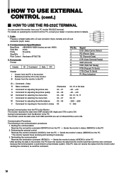
... data -20 ~ +20 -20 ~ +20 00, 01, 10, 11 00, 01 -256 ~ +255 0 ~ 655 During Communication from the PC to the Monitor The monitor receives the data when DSR remains ON (high) and CTS is set to ON. Performing the external control Receives the control command (!XXXXCr) from the... the communication is the communication procedures. 1. HOW TO USE EXTERNAL CONTROL (cont.) Ⅵ HOW TO USE THE RS-232C TERMINAL You can control the monitor from the monitor to the PC Pin No. 1 2 3 4 5 6 7 8 9 Signal DCD (Data Carrier Detect) RD (Recive Data) TD (Transmit Data) DTR (Data Terminal Ready) GND (...
... data -20 ~ +20 -20 ~ +20 00, 01, 10, 11 00, 01 -256 ~ +255 0 ~ 655 During Communication from the PC to the Monitor The monitor receives the data when DSR remains ON (high) and CTS is set to ON. Performing the external control Receives the control command (!XXXXCr) from the... the communication is the communication procedures. 1. HOW TO USE EXTERNAL CONTROL (cont.) Ⅵ HOW TO USE THE RS-232C TERMINAL You can control the monitor from the monitor to the PC Pin No. 1 2 3 4 5 6 7 8 9 Signal DCD (Data Carrier Detect) RD (Recive Data) TD (Transmit Data) DTR (Data Terminal Ready) GND (...
BTH1700 User Guide
Page 19
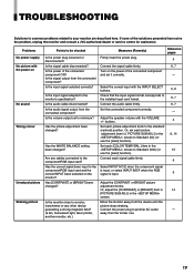
... cable disconnected? Is the audio signal output from the device until the picture stops shaking. Reference pages 5 6, 7 - Move the monitor away from the connected component? away from the connected component? ENGLISH TROUBLESHOOTING Solutions to common problems related to the installed input card format.... Is the power of the solutions presented here solve the problem, unplug the monitor and consult a JVC-authorised dealer or service centre for assistance. Is the signal output from the former one. 19 Is ...
... cable disconnected? Is the audio signal output from the device until the picture stops shaking. Reference pages 5 6, 7 - Move the monitor away from the connected component? away from the connected component? ENGLISH TROUBLESHOOTING Solutions to common problems related to the installed input card format.... Is the power of the solutions presented here solve the problem, unplug the monitor and consult a JVC-authorised dealer or service centre for assistance. Is the signal output from the former one. 19 Is ...
BTH1700 User Guide
Page 20
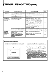
...each other until the interference disappears or turn the power off on the screen as a white cloth) is not harmful. ● The monitor emits a strange sound when the room temperature changes suddenly. When the UNDER SCAN or ASPECT button is not a malfunction. These lines are... to a normal buildup of the external control to control the monitor locally. Move the monitors away from each setting. POSITION) in the [SIZE/POSI. Change the setting of static electricity on the monitor. Reference pages 4 15, 16 4 16 17, 18 The following are not a malfunction. This phenomenon is...
...each other until the interference disappears or turn the power off on the screen as a white cloth) is not harmful. ● The monitor emits a strange sound when the room temperature changes suddenly. When the UNDER SCAN or ASPECT button is not a malfunction. These lines are... to a normal buildup of the external control to control the monitor locally. Move the monitors away from each setting. POSITION) in the [SIZE/POSI. Change the setting of static electricity on the monitor. Reference pages 4 15, 16 4 16 17, 18 The following are not a malfunction. This phenomenon is...
BTH1700 User Guide
Page 21
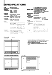
...(using the BT-YA701P) 480i/576i/480p/1080i (60 Hz/24pSF)/720p (using the BT-YA702P) D1 serial digital (using the BT-YA703P) HD serial digital (using the BT-YA704P) Ⅲ Remote Inputs : • Point-of the actual product may differ slightly. * Dimensions and weight... ASPECT AREA MARKER SLOT 1 SLOT 2 SLOT 3 A B C D E F INPUT SELECT POWER 68 286 21 SPECIFICATIONS Ⅲ Type : Multi-format monitor Ⅲ Picture Tube : 17" measured diagonally Ⅲ Effective Screen Size : Width : 330 mm Height : 250 mm Diagonal : 410 mm Ⅲ Scanning Frequency : H : 15...
...(using the BT-YA701P) 480i/576i/480p/1080i (60 Hz/24pSF)/720p (using the BT-YA702P) D1 serial digital (using the BT-YA703P) HD serial digital (using the BT-YA704P) Ⅲ Remote Inputs : • Point-of the actual product may differ slightly. * Dimensions and weight... ASPECT AREA MARKER SLOT 1 SLOT 2 SLOT 3 A B C D E F INPUT SELECT POWER 68 286 21 SPECIFICATIONS Ⅲ Type : Multi-format monitor Ⅲ Picture Tube : 17" measured diagonally Ⅲ Effective Screen Size : Width : 330 mm Height : 250 mm Diagonal : 410 mm Ⅲ Scanning Frequency : H : 15...
BTH1700 User Guide
Page 22
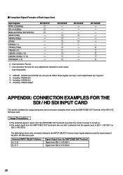
... SWITCHED OUT Terminal Signal from SDI 1 / HD SDI 1 Signal from the signals input to SDI 1 / HD SDI 1 or SDI 2 / HD SDI 2. R - R - - - - - - Usage Precautions ● The selected signal is output from the SWITCHED OUT terminal only when the monitor's power is turned on. ● The ...output signal from the SWITCHED OUT terminal is the one that is selected from SDI 2 / HD SDI 2 22 R R R ⅜ R ⅜ R ⅜ R R : Input possible...
... SWITCHED OUT Terminal Signal from SDI 1 / HD SDI 1 Signal from the signals input to SDI 1 / HD SDI 1 or SDI 2 / HD SDI 2. R - R - - - - - - Usage Precautions ● The selected signal is output from the SWITCHED OUT terminal only when the monitor's power is turned on. ● The ...output signal from the SWITCHED OUT terminal is the one that is selected from SDI 2 / HD SDI 2 22 R R R ⅜ R ⅜ R ⅜ R R : Input possible...
BTH1700 User Guide
Page 23
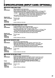
... (INPUT CARD: OPTIONAL) Ⅵ BT-YA701P: VIDEO INPUT CARD Type Inputs/Outputs Required slots Power consumption Weight Dimensions (W x H x D) : Video input card for multi-format monitor : Digital input (HD SDI 1/HD SDI 2): 2 lines, BNC connector x 2 (0.8 V (p-p), 75 Ω) Digital output (SWITCHED OUT): 1 line, BNC connector x 1 (0.8 V (p-p), 75 Ω) Audio signal: 1 line (monaural), RCA pin x 2 (0.5 V (rms), high...
... (INPUT CARD: OPTIONAL) Ⅵ BT-YA701P: VIDEO INPUT CARD Type Inputs/Outputs Required slots Power consumption Weight Dimensions (W x H x D) : Video input card for multi-format monitor : Digital input (HD SDI 1/HD SDI 2): 2 lines, BNC connector x 2 (0.8 V (p-p), 75 Ω) Digital output (SWITCHED OUT): 1 line, BNC connector x 1 (0.8 V (p-p), 75 Ω) Audio signal: 1 line (monaural), RCA pin x 2 (0.5 V (rms), high...


