

BTH1700BP User Guide
Page 1
Operating Instructions Multi-Format Monitor Model BT-H1700BP MUTING VOLUME UNDER DEGAUSS SCAN PULSE CROSS COLOR OFF MENU BLUE CHECK ASPECT AREA MARKER SLOT 1 SLOT 2 SLOT 3 A B C D E F INPUT SELECT POWER Before attempting to connect, operate or adjust this product, please read these instructions completely. Printed in Japan VQT0G67-1 P LCT1464-001B 1003-MK-MW-VP
Operating Instructions Multi-Format Monitor Model BT-H1700BP MUTING VOLUME UNDER DEGAUSS SCAN PULSE CROSS COLOR OFF MENU BLUE CHECK ASPECT AREA MARKER SLOT 1 SLOT 2 SLOT 3 A B C D E F INPUT SELECT POWER Before attempting to connect, operate or adjust this product, please read these instructions completely. Printed in Japan VQT0G67-1 P LCT1464-001B 1003-MK-MW-VP
BTH1700BP User Guide
Page 2
...high voltage circuitry. Improper operations, in your own safety and that contain lead. only) CAUTION: Changes or modification not approved by PANASONIC could deform the cabinet or cause the performance of these instructions, all the following precautions. This equipment generates, uses, and can...; HANDLING • Avoid shocks or vibrations. SCREEN BURN • It is excessively dirty, use a magnet eraser to degauss the monitor's cathode ray tube from the unit - For your community due to provide reasonable protection against harmful interference when the equipment is equipped...
...high voltage circuitry. Improper operations, in your own safety and that contain lead. only) CAUTION: Changes or modification not approved by PANASONIC could deform the cabinet or cause the performance of these instructions, all the following precautions. This equipment generates, uses, and can...; HANDLING • Avoid shocks or vibrations. SCREEN BURN • It is excessively dirty, use a magnet eraser to degauss the monitor's cathode ray tube from the unit - For your community due to provide reasonable protection against harmful interference when the equipment is equipped...
BTH1700BP User Guide
Page 5
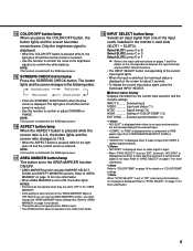
...page 17 for more information. 5 Selected input VIDEO Input card status (*1) NTSC Signal format (*2) HIGH Setting of the input cards installed in the monitor's card slots (SLOT1 - Refer to "SYNC SELECT" on page 17 for more information. *3 Note Refer to ON, the button lights. The ... or D Select SLOT3: press E or F Refer to the input card instructions on pages 7 and 8 for details on the current input selection and the monitor settings. settings. *4 Note When "SYNC SELECT" is set to "INT." (internal synchronization), no video signal is input. • When "SYNC SELECT" is...
...page 17 for more information. 5 Selected input VIDEO Input card status (*1) NTSC Signal format (*2) HIGH Setting of the input cards installed in the monitor's card slots (SLOT1 - Refer to "SYNC SELECT" on page 17 for more information. *3 Note Refer to ON, the button lights. The ... or D Select SLOT3: press E or F Refer to the input card instructions on pages 7 and 8 for details on the current input selection and the monitor settings. settings. *4 Note When "SYNC SELECT" is set to "INT." (internal synchronization), no video signal is input. • When "SYNC SELECT" is...
BTH1700BP User Guide
Page 6
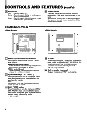
...installed in these slots. NOTE: It is ON, the power lamp on the front panel lights in yellow and the monitor enters the stand-by mode. • I : ON ⅜ : OFF 24 AC inlet Power input connector.... : The main power is OFF (in stand-by mode). RS-232C terminal (Lower): Enables the monitor to turn the monitor's power ON or OFF when the main power is ON (in the set-up menu, it takes...normal operation mode). 20 POWER switch Press the power switch to page 10 for controlling the monitor from a personal computer via a serial communication. 22 Input card slots (SLOT 1 - SLOT 3) Optional ...
...installed in these slots. NOTE: It is ON, the power lamp on the front panel lights in yellow and the monitor enters the stand-by mode. • I : ON ⅜ : OFF 24 AC inlet Power input connector.... : The main power is OFF (in stand-by mode). RS-232C terminal (Lower): Enables the monitor to turn the monitor's power ON or OFF when the main power is ON (in the set-up menu, it takes...normal operation mode). 20 POWER switch Press the power switch to page 10 for controlling the monitor from a personal computer via a serial communication. 22 Input card slots (SLOT 1 - SLOT 3) Optional ...
BTH1700BP User Guide
Page 7
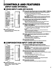
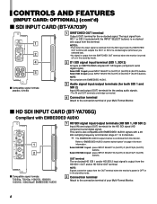
...the "COLOR SYSTEM". NOTES: • When an external synchronized signal is input, external synchronization is input to the connection terminal of your Multi-Format Monitor. 7 COMPONENT/RGB INPUT CARD (BT-YA702P) G/Y IN OUT B/PB/B-Y 1 IN OUT R/PR/R-Y IN OUT HD/CS 4 IN OUT VD...and output (OUT) terminals for both VIDEO 1 and VIDEO 2) Input (IN) and output (OUT) terminals for the composite video signals of your Multi-Format Monitor. 7 Select VIDEO 2: press INPUT SELECT B (SLOT1)/D (SLOT2)/F (SLOT3) buttons. * The IN and OUT terminals are bridge-connected (auto termination). 2...
...the "COLOR SYSTEM". NOTES: • When an external synchronized signal is input, external synchronization is input to the connection terminal of your Multi-Format Monitor. 7 COMPONENT/RGB INPUT CARD (BT-YA702P) G/Y IN OUT B/PB/B-Y 1 IN OUT R/PR/R-Y IN OUT HD/CS 4 IN OUT VD...and output (OUT) terminals for both VIDEO 1 and VIDEO 2) Input (IN) and output (OUT) terminals for the composite video signals of your Multi-Format Monitor. 7 Select VIDEO 2: press INPUT SELECT B (SLOT1)/D (SLOT2)/F (SLOT3) buttons. * The IN and OUT terminals are bridge-connected (auto termination). 2...
BTH1700BP User Guide
Page 8
..."EMBEDDED AUDIO channel switch button" on page 4 for the re-clocked signal. The EMBEDDED AUDIO output channel is output from the OUT terminal when the monitor's power is also compatible with EMBEDDED AUDIO signals with EMBEDDED AUDIO. 3 Audio signal input/output terminals (for both SDI 1 and SDI 2) Input ...still outputs the SDI 1 or SDI 2 re-clocked signal (whichever you selected last). • No signal is output from the SWITCHED OUT terminal when the monitor is re-clocked and output from SDI 1 or SDI 2 (selected with EMBEDDED AUDIO E.AUDIO HD SDI 1 IN OUT E.AUDIO 1 HD SDI 2 IN 2...
..."EMBEDDED AUDIO channel switch button" on page 4 for the re-clocked signal. The EMBEDDED AUDIO output channel is output from the OUT terminal when the monitor's power is also compatible with EMBEDDED AUDIO signals with EMBEDDED AUDIO. 3 Audio signal input/output terminals (for both SDI 1 and SDI 2) Input ...still outputs the SDI 1 or SDI 2 re-clocked signal (whichever you selected last). • No signal is output from the SWITCHED OUT terminal when the monitor is re-clocked and output from SDI 1 or SDI 2 (selected with EMBEDDED AUDIO E.AUDIO HD SDI 1 IN OUT E.AUDIO 1 HD SDI 2 IN 2...
BTH1700BP User Guide
Page 9
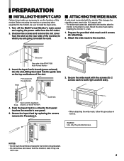
... the Input Card's board (green-colored) into the slot, fitting the board into the guide rails on the rear side of the monitor) in which you are going to install the card. Ⅵ ATTACHINGTHEWIDE MASK A wide mask is provided with the screws (fix 2...cover Rear side of this procedure in Procedure 2. • When detaching the wide mask, follow this monitor. Before mounting the monitor or connecting other equipment to the monitor, be attached to the monitor after the monitor is of the slot. PREPARATION Ⅵ INSTALLINGTHEINPUTCARD Optional input cards are necessary to use . 9 Attach...
... the Input Card's board (green-colored) into the slot, fitting the board into the guide rails on the rear side of the monitor) in which you are going to install the card. Ⅵ ATTACHINGTHEWIDE MASK A wide mask is provided with the screws (fix 2...cover Rear side of this procedure in Procedure 2. • When detaching the wide mask, follow this monitor. Before mounting the monitor or connecting other equipment to the monitor, be attached to the monitor after the monitor is of the slot. PREPARATION Ⅵ INSTALLINGTHEINPUTCARD Optional input cards are necessary to use . 9 Attach...
BTH1700BP User Guide
Page 10
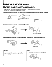
...; The provided Power Cord Holder prevents accidental disconnection of the AC power cord from the AC inlet. • The Power Cord Holder consists of the monitor with the case. Caution: • A different plug shape will result in the cover being attached to a different position. • Check to open the cover. 10...
...; The provided Power Cord Holder prevents accidental disconnection of the AC power cord from the AC inlet. • The Power Cord Holder consists of the monitor with the case. Caution: • A different plug shape will result in the cover being attached to a different position. • Check to open the cover. 10...
BTH1700BP User Guide
Page 11
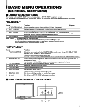
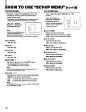
... display ON/OFF. * Switches the display on the type of display. BASIC MENU OPERATIONS (MAIN MENU, SET-UP MENU) Ⅵ ABOUT MENU SCREENS This monitor features a MAIN MENU (main menu screen) and a SET-UP MENU (setup menu screen). "SET-UP MENU" Items 1 FUNCTION SETTING 2 PICTURE SUB ADJ...screen ratio is 16:9. Adjusts the size or position of the input card slots. 3 sub menu POSI. Sets the control lock preventing the monitor from misuse. Sets all reset Functions Selects the control systems for initial setup. "MAIN MENU" Items Functions Displays 1 APERTURE CONTROL Compensates the ...
... display ON/OFF. * Switches the display on the type of display. BASIC MENU OPERATIONS (MAIN MENU, SET-UP MENU) Ⅵ ABOUT MENU SCREENS This monitor features a MAIN MENU (main menu screen) and a SET-UP MENU (setup menu screen). "SET-UP MENU" Items 1 FUNCTION SETTING 2 PICTURE SUB ADJ...screen ratio is 16:9. Adjusts the size or position of the input card slots. 3 sub menu POSI. Sets the control lock preventing the monitor from misuse. Sets all reset Functions Selects the control systems for initial setup. "MAIN MENU" Items Functions Displays 1 APERTURE CONTROL Compensates the ...
BTH1700BP User Guide
Page 17
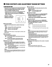
...signal is synchronized with an external signal from an external sync terminal. 7 RUSH DELAY TIME Sets the time when the power supply to the monitor's circuits (excluding the micro computers) starts after the power switch is set to a standard output level for all 8 signal channels. Sets ... will be. (Each channel's level becomes half for 1- 2 channel, 1/4 for 1- 4 channel.) 7 HOUR METER X100h Displays the total usage time of the monitor in hundredhour units. • 000 ~ 655 NOTES: • When the timer passes 655, it is installed.) Press the button to display the setting menu illustrated...
...signal is synchronized with an external signal from an external sync terminal. 7 RUSH DELAY TIME Sets the time when the power supply to the monitor's circuits (excluding the micro computers) starts after the power switch is set to a standard output level for all 8 signal channels. Sets ... will be. (Each channel's level becomes half for 1- 2 channel, 1/4 for 1- 4 channel.) 7 HOUR METER X100h Displays the total usage time of the monitor in hundredhour units. • 000 ~ 655 NOTES: • When the timer passes 655, it is installed.) Press the button to display the setting menu illustrated...
BTH1700BP User Guide
Page 18
... : 00 : 00 : 00 : 00 :SMPTE When the RGB signal is adjusted to the center. • Can also be used to make fine adjustments between the monitors.
... : 00 : 00 : 00 : 00 :SMPTE When the RGB signal is adjusted to the center. • Can also be used to make fine adjustments between the monitors.
BTH1700BP User Guide
Page 20
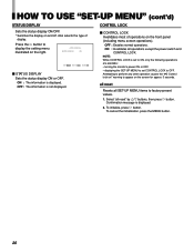
... Resets all SET-UP MENU items to perform any other operation causes the " Control lock on!" To initialize, press button. warning to OFF. turning the monitor's power ON or OFF. - Select "all operations except the power switch and CONTROL LOCK. displaying the SET-UP MENU to set to display the setting...
... Resets all SET-UP MENU items to perform any other operation causes the " Control lock on!" To initialize, press button. warning to OFF. turning the monitor's power ON or OFF. - Select "all operations except the power switch and CONTROL LOCK. displaying the SET-UP MENU to set to display the setting...
BTH1700BP User Guide
Page 21
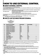
... terminal to "AREA MARKER" on page 14 for remote control is possible. HOW TO USE EXTERNAL CONTROL 7 ABOUT EXTERNAL CONTROL The Multi-Format Monitor has two external control terminals. Functions to INPUT F 8 COLOR OFF 9 AREA MARKER 10 ASPECT 11 TALLY SELECT 12 AREA MARKER set-up...OFF Invalid Valid *2 *1 : The TRIGGER (trigger contact) system switches each function by Pulse Control, that is the MAKE/TRIGGER terminal, which allows the monitor to be short-circuited to GND (15th terminal). The other terminal used for details. When trigger contact is in the AREA MARKER menu is the...
... terminal to "AREA MARKER" on page 14 for remote control is possible. HOW TO USE EXTERNAL CONTROL 7 ABOUT EXTERNAL CONTROL The Multi-Format Monitor has two external control terminals. Functions to INPUT F 8 COLOR OFF 9 AREA MARKER 10 ASPECT 11 TALLY SELECT 12 AREA MARKER set-up...OFF Invalid Valid *2 *1 : The TRIGGER (trigger contact) system switches each function by Pulse Control, that is the MAKE/TRIGGER terminal, which allows the monitor to be short-circuited to GND (15th terminal). The other terminal used for details. When trigger contact is in the AREA MARKER menu is the...
BTH1700BP User Guide
Page 22
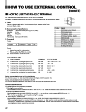
...item W Command for adjusting the white balance C Command for inquiring for details. 9 4 1. If the PC does not receive the status from the monitor after sending the command, re-send the command. 22 Communication Procedures The following is the communication procedures. 1. Cable Prepare a straight cable with a D-sub...20 or -31 ~ +31 -20 ~ +20 00, 01, 10, 11 00, 01 -256 ~ +255 0 ~ 655 During Communication from the PC to the Monitor The monitor receives the data when DSR remains ON (high) and CTS is set ; 4800) Data Bits : 8 bits Parity Stop Bits : No parity :1 Flow Control : Hardware ...
...item W Command for adjusting the white balance C Command for inquiring for details. 9 4 1. If the PC does not receive the status from the monitor after sending the command, re-send the command. 22 Communication Procedures The following is the communication procedures. 1. Cable Prepare a straight cable with a D-sub...20 or -31 ~ +31 -20 ~ +20 00, 01, 10, 11 00, 01 -256 ~ +255 0 ~ 655 During Communication from the PC to the Monitor The monitor receives the data when DSR remains ON (high) and CTS is set ; 4800) Data Bits : 8 bits Parity Stop Bits : No parity :1 Flow Control : Hardware ...
BTH1700BP User Guide
Page 23
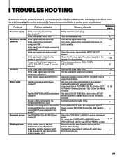
... of the solutions presented here solve the problem, unplug the monitor and consult a Panasonic-authorized dealer or service center for assistance. Shaking picture Is the monitor close to the component/RGB input card? Move the monitor away from the connected component? Connect the signal cable firmly....power turned OFF? Has [CONTRAST] or [BRIGHT] been changed? Connect each [COLOR TEMP./BAL.] item in the screen to the monitor's specification? Is the audio signal output from the device until the picture stops shaking. Check that the input signal format corresponds to ...
... of the solutions presented here solve the problem, unplug the monitor and consult a Panasonic-authorized dealer or service center for assistance. Shaking picture Is the monitor close to the component/RGB input card? Move the monitor away from the connected component? Connect the signal cable firmly....power turned OFF? Has [CONTRAST] or [BRIGHT] been changed? Connect each [COLOR TEMP./BAL.] item in the screen to the monitor's specification? Is the audio signal output from the device until the picture stops shaking. Check that the input signal format corresponds to ...
BTH1700BP User Guide
Page 24
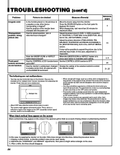
... B C D E F INPUT SELECT POWER • About CRT tube reflection (when Zoom mode is not being shaken or jolted during shipment. Move the monitors away from each other device incorporating a magnet? Maximize the "CONTRAST" and "BRIGHT" adjustments, then place a bright white rectangle on the side. When degaussing...ASPECT AREA MARKER SLOT 1 SLOT 2 SLOT 3 A B C D E F INPUT SELECT POWER In this does not get rid of the monitor been changed with the power on the front panel to degauss the screen. Has the position of the lines, follow the procedure below. 1. POSITION...
... B C D E F INPUT SELECT POWER • About CRT tube reflection (when Zoom mode is not being shaken or jolted during shipment. Move the monitors away from each other device incorporating a magnet? Maximize the "CONTRAST" and "BRIGHT" adjustments, then place a bright white rectangle on the side. When degaussing...ASPECT AREA MARKER SLOT 1 SLOT 2 SLOT 3 A B C D E F INPUT SELECT POWER In this does not get rid of the monitor been changed with the power on the front panel to degauss the screen. Has the position of the lines, follow the procedure below. 1. POSITION...
BTH1700BP User Guide
Page 25
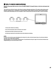
... 2 SLOT 3 A B C D E F INPUT SELECT POWER 1. Turn off the main power switch on the front control panel start blinking... This monitor has a self-check function, which indicators are blinking. If this happens, turn on again. 7 SELF-CHECK INDICATIONS When the screen goes blank, and ...one or more of the monitor. 3. Whenever a problem occurs, a combination of "self-check indicators" (INPUT SELECT A through F buttons on the back of the INPUT SELECT A...
... 2 SLOT 3 A B C D E F INPUT SELECT POWER 1. Turn off the main power switch on the front control panel start blinking... This monitor has a self-check function, which indicators are blinking. If this happens, turn on again. 7 SELF-CHECK INDICATIONS When the screen goes blank, and ...one or more of the monitor. 3. Whenever a problem occurs, a combination of "self-check indicators" (INPUT SELECT A through F buttons on the back of the INPUT SELECT A...
BTH1700BP User Guide
Page 26
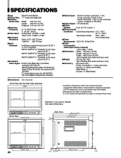
...-YA703P) HD serial digital (using the BT- Design and specifications subject to change without notice. 183 (7-1/4")* 331 (13-1/8")* Asterisks (*) are approximate. * E. & O.E. SPECIFICATIONS 7 Type : Multi-Format Monitor 7Picture Tube : 17" measured diagonally 7 Effective Screen Size : Width : 330 mm (13") Height : 250 mm (9-7/8") Diagonal : 410 mm (16-1/4") 7 Scanning Frequency : H : 15 kHz/27 kHz...
...-YA703P) HD serial digital (using the BT- Design and specifications subject to change without notice. 183 (7-1/4")* 331 (13-1/8")* Asterisks (*) are approximate. * E. & O.E. SPECIFICATIONS 7 Type : Multi-Format Monitor 7Picture Tube : 17" measured diagonally 7 Effective Screen Size : Width : 330 mm (13") Height : 250 mm (9-7/8") Diagonal : 410 mm (16-1/4") 7 Scanning Frequency : H : 15 kHz/27 kHz...


