Operating Instructions
Page 2
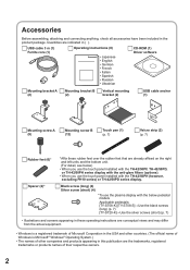
...42/50PF, TH-42/50PD, or TH-42/50PH series display with the anti-glare filters (options). • When you use the plasma display with the TH-42/50PH (however, excluding PH10 series) or TH-42/50PD series display. USB cable 3 m (1) Ferrite core (1) Operating...) (4) Silver screw (short) (4) *To use the touch panel installed with the below pedestal models Applicable pedestals: [TY-ST08-K] [TY-ST08-S]→Use the black screws (long) (p. 7) [TY-ST20-K]→Use the silver screws (short) (p. 7) • Illustrations and screens appearing in these rubber feet over the rubber feet that ...
...42/50PF, TH-42/50PD, or TH-42/50PH series display with the anti-glare filters (options). • When you use the plasma display with the TH-42/50PH (however, excluding PH10 series) or TH-42/50PD series display. USB cable 3 m (1) Ferrite core (1) Operating...) (4) Silver screw (short) (4) *To use the touch panel installed with the below pedestal models Applicable pedestals: [TY-ST08-K] [TY-ST08-S]→Use the black screws (long) (p. 7) [TY-ST20-K]→Use the silver screws (short) (p. 7) • Illustrations and screens appearing in these rubber feet over the rubber feet that ...

Operating Instructions
Page 4
...by a qualified technician. • If the bracket is installed incorrectly, the display may fall down or place a plasma display on the touch panel. • The edge of the plasma display will not be used for a long time, unplug the USB cable. • To ensure safety, be sure to ...where it may damage the cord, and cause a fire or electric shock. Using the product with touch panel operation. Do not move the equipment after attaching the touch panel unit to the plasma display. • The weight of the infrared transmissive part is damaged, unplug the USB cable and contact...
...by a qualified technician. • If the bracket is installed incorrectly, the display may fall down or place a plasma display on the touch panel. • The edge of the plasma display will not be used for a long time, unplug the USB cable. • To ensure safety, be sure to ...where it may damage the cord, and cause a fire or electric shock. Using the product with touch panel operation. Do not move the equipment after attaching the touch panel unit to the plasma display. • The weight of the infrared transmissive part is damaged, unplug the USB cable and contact...
Operating Instructions
Page 6
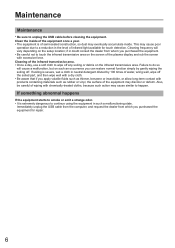
... poor operation due to happen. Failure to do so will vary depending on the screen of the infrared transmissive area. • Once a day, use a soft cloth to touch the infrared transmissive area on the setup location; Maintenance Maintenance * Be sure to smoke... or emit a strange odor. • It is of infrared light available for repair. 6 If soiling is severe, wet a cloth in such a malfunctioning state. Clean the inside . Cleaning of the plasma display and rub the screen...
... poor operation due to happen. Failure to do so will vary depending on the screen of the infrared transmissive area. • Once a day, use a soft cloth to touch the infrared transmissive area on the setup location; Maintenance Maintenance * Be sure to smoke... or emit a strange odor. • It is of infrared light available for repair. 6 If soiling is severe, wet a cloth in such a malfunctioning state. Clean the inside . Cleaning of the plasma display and rub the screen...
Operating Instructions
Page 7
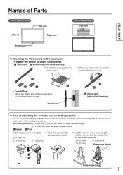
... the Velcro strip. Ԙ ㎤ ㎥ ㎦ ㎥ • Touch Pen Attach the Velcro strip to the touch panel so as shown. Applicable pedestals: [TY-ST08-K] [TY-ST08-S]→Use the black screws (long) [TY-ST20-K]→Use the silver screws (short) Spacer Pole ...arrow. Lock the spacer to the pedestal To use the plasma display with the below included accessories Touch pen Velcro strip (with the touch panel on attaching the included spacer to the pole using the included screws that are suitable ...
... the Velcro strip. Ԙ ㎤ ㎥ ㎦ ㎥ • Touch Pen Attach the Velcro strip to the touch panel so as shown. Applicable pedestals: [TY-ST08-K] [TY-ST08-S]→Use the black screws (long) [TY-ST20-K]→Use the silver screws (short) Spacer Pole ...arrow. Lock the spacer to the pedestal To use the plasma display with the below included accessories Touch pen Velcro strip (with the touch panel on attaching the included spacer to the pole using the included screws that are suitable ...
Operating Instructions
Page 9
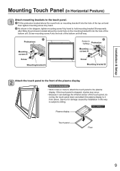
...screws A Screw Screw Mounting bracket A Mounting bracket B 2 Attach the touch panel to the front of the plasma display. INCORRECT Plasma display Touch panel Floor 9 Installation & Setup Mounting Touch Panel (in Horizontal Posture) 1 Attach mounting brackets to the touch panel. Fit the protrusion located above the round hole on ...way is dropped, injuries may occur. • Because it can damage the infrared sensor of the touch panel, do not lay the touch panel down and attach the plasma display to it from above the round hole on Assembly • Work in two or more ...
...screws A Screw Screw Mounting bracket A Mounting bracket B 2 Attach the touch panel to the front of the plasma display. INCORRECT Plasma display Touch panel Floor 9 Installation & Setup Mounting Touch Panel (in Horizontal Posture) 1 Attach mounting brackets to the touch panel. Fit the protrusion located above the round hole on ...way is dropped, injuries may occur. • Because it can damage the infrared sensor of the touch panel, do not lay the touch panel down and attach the plasma display to it from above the round hole on Assembly • Work in two or more ...
Operating Instructions
Page 10
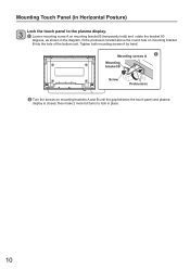
...bracket B Screw Protrusions Turn the screws on mounting brackets A and B until the gap between the touch panel and plasma display is closed, then make 2 more full turns to the plasma display. Loosen mounting screw A on mounting bracket B (temporarily held) and rotate the bracket 90 degrees..., as shown in place. 10 Mounting Touch Panel (in Horizontal Posture) 3 Lock the touch panel to lock in the diagram, fi...
...bracket B Screw Protrusions Turn the screws on mounting brackets A and B until the gap between the touch panel and plasma display is closed, then make 2 more full turns to the plasma display. Loosen mounting screw A on mounting bracket B (temporarily held) and rotate the bracket 90 degrees..., as shown in place. 10 Mounting Touch Panel (in Horizontal Posture) 3 Lock the touch panel to lock in the diagram, fi...
Operating Instructions
Page 11
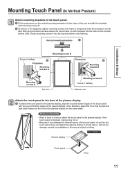
... by installation in halfway Bottom unit 2 Attach the touch panel to the front of the plasma display. To attach the touch panel to the plasma display, align the top and bottom edges of the touch panel with mounting screws B. As shown ...diagrams, tighten mounting screws A by hand to temporarily hold the brackets A and B after fitting the protrusions located above . INCORRECT Plasma display Touch panel Floor 11 Vertical mounting brackets Installation & Setup Mounting screws B Screw in halfway Protrusion Mounting bracket A Protrusion &#...
... by installation in halfway Bottom unit 2 Attach the touch panel to the front of the plasma display. To attach the touch panel to the plasma display, align the top and bottom edges of the touch panel with mounting screws B. As shown ...diagrams, tighten mounting screws A by hand to temporarily hold the brackets A and B after fitting the protrusions located above . INCORRECT Plasma display Touch panel Floor 11 Vertical mounting brackets Installation & Setup Mounting screws B Screw in halfway Protrusion Mounting bracket A Protrusion &#...

Operating Instructions
Page 12
...B Top unit Bottom unit Turn the screws on the brackets into the holes of the touch panel as "Vertical". (p. 39) 12 Mounting Touch Panel (in Vertical Posture) 3 Lock the touch panel to the plasma display. Loosen mounting screws A on mounting brackets A and B (temporarily held) and rotate...shown in the diagrams, fit the protrusions located above the round holes on mounting brackets A and B until the gap between the touch panel and plasma display is closed, then make 2 more full turns to lock in vertical position, set the sensor position of the top and bottom units...
...B Top unit Bottom unit Turn the screws on the brackets into the holes of the touch panel as "Vertical". (p. 39) 12 Mounting Touch Panel (in Vertical Posture) 3 Lock the touch panel to the plasma display. Loosen mounting screws A on mounting brackets A and B (temporarily held) and rotate...shown in the diagrams, fit the protrusions located above the round holes on mounting brackets A and B until the gap between the touch panel and plasma display is closed, then make 2 more full turns to lock in vertical position, set the sensor position of the top and bottom units...
Operating Instructions
Page 16
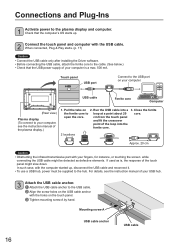
... For details, see the instruction manual of your computer, see the instruction manual of the plasma display.) 1. Mounting screw A USB cable anchor USB cable 16 Pull the tabs on your fingers, for instance, or touching the screen while connecting the USB cable might slow down. cm from the... touch panel and fit the crossover point of the touch panel might be supplied to the USB cable. Align the screw holes...
... For details, see the instruction manual of your computer, see the instruction manual of the plasma display.) 1. Mounting screw A USB cable anchor USB cable 16 Pull the tabs on your fingers, for instance, or touching the screen while connecting the USB cable might slow down. cm from the... touch panel and fit the crossover point of the touch panel might be supplied to the USB cable. Align the screw holes...
Operating Instructions
Page 35
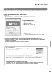
... disconnecting USB devices that at right may appear when connecting multiple touch panels. Restrictions on the "Settings" tab. Click this button. Touch Panel Setup Multiple Monitor Setup Multiple plasma displays can be connected to that are changed after disconnecting supported monitors... and reconnecting new ones, either reregister the touch panel or cancel the registration. 35 Operation It ...
... disconnecting USB devices that at right may appear when connecting multiple touch panels. Restrictions on the "Settings" tab. Click this button. Touch Panel Setup Multiple Monitor Setup Multiple plasma displays can be connected to that are changed after disconnecting supported monitors... and reconnecting new ones, either reregister the touch panel or cancel the registration. 35 Operation It ...

Operating Instructions
Page 37
Touch Panel Setup ■ Calibrating Touch Panels Once registered, touch panels can be calibrated to their respective plasma displays. Start up the setup panel. (p. 20) Select the touch panel to calibrate from the "Touch panels to be set" pull-down menu. • Clicking on the "Select" button and touching a touch panel automatically selects that panel. Click on the "Basic setting" tab. Click this button. The calibration window opens. Make settings. (p. 27) 37 Operation
Touch Panel Setup ■ Calibrating Touch Panels Once registered, touch panels can be calibrated to their respective plasma displays. Start up the setup panel. (p. 20) Select the touch panel to calibrate from the "Touch panels to be set" pull-down menu. • Clicking on the "Select" button and touching a touch panel automatically selects that panel. Click on the "Basic setting" tab. Click this button. The calibration window opens. Make settings. (p. 27) 37 Operation
Operating Instructions
Page 39
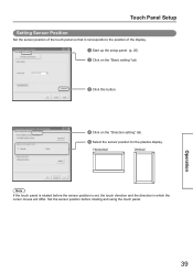
... the "Direction setting" tab. Select the sensor position for the plasma display. Operation 39 Set the sensor position before the sensor position is rotated before rotating and using the touch panel. Horizontal Vertical Note If the touch panel is set, the touch direction and the direction in which the cursor moves will differ.
... the "Direction setting" tab. Select the sensor position for the plasma display. Operation 39 Set the sensor position before the sensor position is rotated before rotating and using the touch panel. Horizontal Vertical Note If the touch panel is set, the touch direction and the direction in which the cursor moves will differ.
Operating Instructions
Page 44
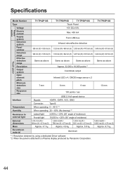
Specifications Model Number TY-TP42P10S TY-TP50P10S TY-TP58P10S TY-TP65P10S Type Touch Panel Power source Touch panel Voltage Electric current Supply system Detection system Panel window Detection range Effective detection range Resolution Output system Optic element pitch Minimum detection size Response .... 5.8 kg 1,550.8 mm(W) × 1,008.2 mm (H) × 47.9 mm (D) Approx. 6.7 kg Aluminum *1 Resolution obtained by using a dedicated Driver software *2 When the panel is attached to a Plasma display produced by Panasonic Corporation. 44
Specifications Model Number TY-TP42P10S TY-TP50P10S TY-TP58P10S TY-TP65P10S Type Touch Panel Power source Touch panel Voltage Electric current Supply system Detection system Panel window Detection range Effective detection range Resolution Output system Optic element pitch Minimum detection size Response .... 5.8 kg 1,550.8 mm(W) × 1,008.2 mm (H) × 47.9 mm (D) Approx. 6.7 kg Aluminum *1 Resolution obtained by using a dedicated Driver software *2 When the panel is attached to a Plasma display produced by Panasonic Corporation. 44