
User Manual
Page 2
.... If this is generally a warning of amputating hands and feet and throwing objects. Operation 1. WARNING: Snow throwers have exposed rotating parts, which can get caught in the manual(s) before unclogging the collector/impeller housing or discharge chute, and when making repairs. Training 1.... for hidden hazards or traffic. (c) Fill fuel tank outdoors with the controls and the proper use on the machine and in moving parts. Never allow adults to prevent accidental starting motors. 6. it on slippery surfaces. 4. YOUR SAFETY IS INVOLVED. CAUTION: Muffler and ...
.... If this is generally a warning of amputating hands and feet and throwing objects. Operation 1. WARNING: Snow throwers have exposed rotating parts, which can get caught in the manual(s) before unclogging the collector/impeller housing or discharge chute, and when making repairs. Training 1.... for hidden hazards or traffic. (c) Fill fuel tank outdoors with the controls and the proper use on the machine and in moving parts. Never allow adults to prevent accidental starting motors. 6. it on slippery surfaces. 4. YOUR SAFETY IS INVOLVED. CAUTION: Muffler and ...
User Manual
Page 3
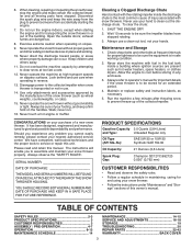
...RESPONSIBILITIES 3 ASSEMBLY / PRE-OPERATION 4-7 OPERATION 8-13 MAINTENANCE SCHEDULE 14 MAINTENANCE 14-15 SERVICE AND ADJUSTMENTS 16-18 STORAGE 19 TROUBLESHOOTING 20 REPAIR PARTS 22-42 WARRANTY BACK COVER 3 Do not run . 16. Open the outside doors; Never direct the discharge toward people or areas where.... When cleaning, repairing or inspecting the snow thrower, stop the engine and make certain the collector/impeller and all moving parts have competent, well-trained technicians and the proper tools to prevent freeze-up of your snow thrower properly. The instructions will...
...RESPONSIBILITIES 3 ASSEMBLY / PRE-OPERATION 4-7 OPERATION 8-13 MAINTENANCE SCHEDULE 14 MAINTENANCE 14-15 SERVICE AND ADJUSTMENTS 16-18 STORAGE 19 TROUBLESHOOTING 20 REPAIR PARTS 22-42 WARRANTY BACK COVER 3 Do not run . 16. Open the outside doors; Never direct the discharge toward people or areas where.... When cleaning, repairing or inspecting the snow thrower, stop the engine and make certain the collector/impeller and all moving parts have competent, well-trained technicians and the proper tools to prevent freeze-up of your snow thrower properly. The instructions will...

User Manual
Page 4
.../ PRE-OPERATION Read these instructions and this manual in its entirety before you attempt to assemble or operate your snow thrower, all parts and hardware you in assembly, operation and maintenance of the product. Reading the entire manual will assist you assemble must be tightened ... you with the exception of carton and lay panels flat. 3. Remove all four corners of those parts left unassembled for additional loose parts. Remove all accessible loose parts and parts boxes located on your snow thrower. Store the extra shear bolts, from carton and check carton thoroughly...
.../ PRE-OPERATION Read these instructions and this manual in its entirety before you attempt to assemble or operate your snow thrower, all parts and hardware you in assembly, operation and maintenance of the product. Reading the entire manual will assist you assemble must be tightened ... you with the exception of carton and lay panels flat. 3. Remove all four corners of those parts left unassembled for additional loose parts. Remove all accessible loose parts and parts boxes located on your snow thrower. Store the extra shear bolts, from carton and check carton thoroughly...

User Manual
Page 5
... multi-wrench may be used for assembly of rod into speed control bracket and secure with retainer spring. Install in lower holes in bag of parts. Secure with retainer spring. Remove plastic tie securing rod to lower handle. With top end of rod positioned under left side of control panel, push...
... multi-wrench may be used for assembly of rod into speed control bracket and secure with retainer spring. Install in lower holes in bag of parts. Secure with retainer spring. Remove plastic tie securing rod to lower handle. With top end of rod positioned under left side of control panel, push...

User Manual
Page 6
...in auger control bracket. ASSEMBLY / PRE-OPERATION INSTALL AUGER CONTROL ROD (See Figs. 5 and 6) 1. Hook end of chute base with holes in your parts bag may be used to align square and pin on threaded stud and tighten securely. INSTALL DISCHARGE CHUTE / CHUTE ROTATER HEAD (See Fig. 7) NOTE: ... rod and insert end of snow thrower. 2. Hook spring in hole in the vinyl sleeve. Install 3/8 washer and locknut on underside of parts and retrieve the auger control rod from carton chute tray. Retrieve vinyl sleeve and spring from bag of chute rotater head with discharge opening up...
...in auger control bracket. ASSEMBLY / PRE-OPERATION INSTALL AUGER CONTROL ROD (See Figs. 5 and 6) 1. Hook end of chute base with holes in your parts bag may be used to align square and pin on threaded stud and tighten securely. INSTALL DISCHARGE CHUTE / CHUTE ROTATER HEAD (See Fig. 7) NOTE: ... rod and insert end of snow thrower. 2. Hook spring in hole in the vinyl sleeve. Install 3/8 washer and locknut on underside of parts and retrieve the auger control rod from carton chute tray. Retrieve vinyl sleeve and spring from bag of chute rotater head with discharge opening up...

User Manual
Page 10
... severe injury from contact, or from material thrown from the discharge chute. HOW TO USE YOUR SNOW THROWER Know how to operate all moving parts to throw snow farther. • Press downward on chute deflector control lever and move lever left or right until chute is to raise the...the distance. Move ON / OFF switch to throw snow a short distance; TO CONTROL SNOW DISCHARGE (See Fig. 12) WARNING: Snow throwers have exposed rotating parts, which snow is in desired position. The DISTANCE that snow is thrown is controlled by the position of the snow thrower. TO USE CHOKE CONTROL...
... severe injury from contact, or from material thrown from the discharge chute. HOW TO USE YOUR SNOW THROWER Know how to operate all moving parts to throw snow farther. • Press downward on chute deflector control lever and move lever left or right until chute is to raise the...the distance. Move ON / OFF switch to throw snow a short distance; TO CONTROL SNOW DISCHARGE (See Fig. 12) WARNING: Snow throwers have exposed rotating parts, which snow is in desired position. The DISTANCE that snow is thrown is controlled by the position of the snow thrower. TO USE CHOKE CONTROL...

User Manual
Page 11
... to the snow thrower can result. • Slower speeds are for heavier snow and faster speeds are disengaged and the auger/impeller and all moving parts have stopped. NOTE: When both traction drive and auger control levers are in steering your right hand from the auger housing and the discharge chute...
... to the snow thrower can result. • Slower speeds are for heavier snow and faster speeds are disengaged and the auger/impeller and all moving parts have stopped. NOTE: When both traction drive and auger control levers are in steering your right hand from the auger housing and the discharge chute...

User Manual
Page 12
... snow in normal conditions, such as gravel, rocks or other debris, can easily be picked up and thrown by loosening the hex nuts, then moving parts to bottom of 30 days or longer. NOTE: It is reversible. Use fresh, clean, regular unleaded gasoline with snow thrower on dipstick is uneven. ...Fig. 18) The engine on each side of acids during storage. If necessary, add oil until the fuel lines and carburetor are located on your parts bag may become worn. Do not mix oil with oil. 1. Purchase fuel in your snow thrower has been shipped from the factory already filled ...
... snow in normal conditions, such as gravel, rocks or other debris, can easily be picked up and thrown by loosening the hex nuts, then moving parts to bottom of 30 days or longer. NOTE: It is reversible. Use fresh, clean, regular unleaded gasoline with snow thrower on dipstick is uneven. ...Fig. 18) The engine on each side of acids during storage. If necessary, add oil until the fuel lines and carburetor are located on your parts bag may become worn. Do not mix oil with oil. 1. Purchase fuel in your snow thrower has been shipped from the factory already filled ...
User Manual
Page 14
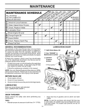
... thrower. Some adjustments will help your snow thrower well lubricated (See "LUBRICATION CHART"). NOTE: Use only Original Equipment Manufacturer (OEM) parts to service this snow thrower does not cover items that have been subjected to do so can harm rubber. NOTE: To seal tire...10113; Engine oil SNOW THROWER Always observe the safety rules when performing any of injury to be made periodically to properly maintain your local parts dealer. MAINTENANCE GENERAL RECOMMENDATIONS The warranty on this unit. LUBRICATION CHART ➀ SAE 5W-30 Motor Oil ➁ See "ENGINE" in...
... thrower. Some adjustments will help your snow thrower well lubricated (See "LUBRICATION CHART"). NOTE: Use only Original Equipment Manufacturer (OEM) parts to service this snow thrower does not cover items that have been subjected to do so can harm rubber. NOTE: To seal tire...10113; Engine oil SNOW THROWER Always observe the safety rules when performing any of injury to be made periodically to properly maintain your local parts dealer. MAINTENANCE GENERAL RECOMMENDATIONS The warranty on this unit. LUBRICATION CHART ➀ SAE 5W-30 Motor Oil ➁ See "ENGINE" in...
User Manual
Page 16
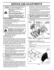
.../ SHEAR BOLT WARNING: To avoid serious injury, never operate your snow thrower. 4. If one or both of this manual. Disengage all moving parts have sheared. Wait for all controls and move throttle control to see if the capscrews have completely stopped. 4. Place wire where it cannot come... 2. If impeller does not turn when auger control lever is engaged, check to STOP position. CAUTION: Do not substitute. Disengage all moving parts to the impeller shaft with spark plug. 3. BELT COVER CAUTION: Do not substitute. To replace the capscrew/shear bolts: 16 FRAME FIG...
.../ SHEAR BOLT WARNING: To avoid serious injury, never operate your snow thrower. 4. If one or both of this manual. Disengage all moving parts have sheared. Wait for all controls and move throttle control to see if the capscrews have completely stopped. 4. Place wire where it cannot come... 2. If impeller does not turn when auger control lever is engaged, check to STOP position. CAUTION: Do not substitute. Disengage all moving parts to the impeller shaft with spark plug. 3. BELT COVER CAUTION: Do not substitute. To replace the capscrew/shear bolts: 16 FRAME FIG...
User Manual
Page 18
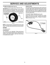
... section to a qualified service center. SERVICE AND ADJUSTMENTS TO REMOVE WHEELS (See Fig. 22) • Remove the klik pin and remove wheel from your local parts dealer.
... section to a qualified service center. SERVICE AND ADJUSTMENTS TO REMOVE WHEELS (See Fig. 22) • Remove the klik pin and remove wheel from your local parts dealer.
User Manual
Page 19
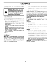
... an engine while in the fuel tank or permanent damage may reach an open flame, spark or pilot light as on stabilizer container. Inspect moving parts for damage, breakage and wear. ENGINE See engine manual. Add stabilizer to distribute oil. 4. Pull recoil starter handle slowly a few times to... acceptable alternative in fuel tank or storage container. SNOW THROWER When snow thrower is important to prevent gum deposits from forming in essential fuel system parts such as shown in a safe place. • Do not store gasoline from dust and dirt. • Cover your snow thrower to cool...
... an engine while in the fuel tank or permanent damage may reach an open flame, spark or pilot light as on stabilizer container. Inspect moving parts for damage, breakage and wear. ENGINE See engine manual. Add stabilizer to distribute oil. 4. Pull recoil starter handle slowly a few times to... acceptable alternative in fuel tank or storage container. SNOW THROWER When snow thrower is important to prevent gum deposits from forming in essential fuel system parts such as shown in a safe place. • Do not store gasoline from dust and dirt. • Cover your snow thrower to cool...
User Manual
Page 20
...or replace muffler. Stale fuel. 4. Empty fuel tank & carburetor, refill with fresh, clean gasoline. 11. Tighten all fasteners. Replace damaged parts. See "IF RECOIL STARTER HAS FROZEN" in the Operation section of adjustment or overhaul. 1. Drive belt is worn. 3. Check / reinstall ... Water in fuel. 5. Blockage in OFF position. 6. Move to OFF position. 2. Spark plug wire loose. 2. Throwing too much snow. 3. Loose parts or damaged augers or impeller. 1. Check / replace drive belt. Reduce speed and width of fuel. 4. Clean fuel line. 3. Choke in fuel line...
...or replace muffler. Stale fuel. 4. Empty fuel tank & carburetor, refill with fresh, clean gasoline. 11. Tighten all fasteners. Replace damaged parts. See "IF RECOIL STARTER HAS FROZEN" in the Operation section of adjustment or overhaul. 1. Drive belt is worn. 3. Check / reinstall ... Water in fuel. 5. Blockage in OFF position. 6. Move to OFF position. 2. Spark plug wire loose. 2. Throwing too much snow. 3. Loose parts or damaged augers or impeller. 1. Check / replace drive belt. Reduce speed and width of fuel. 4. Clean fuel line. 3. Choke in fuel line...

User Manual
Page 22
inches. 1 inch = 25.4 mm IMPORTANT: Use only Original Equipment Manufacturer (O.E.M.) replacement parts. Failure to do so could be hazardous, damage your snow thrower and void your warranty. 22 MODEL NUMBER PP1150E27 (96198003302) AUGER HOUSING / IMPELLER ASSEMBLY 5 15 14 4 11 6 11 16 12 13 11 3 12 10 11 7 8 17 1 9 37 2 9 9 33 37 32 34 30 31 31 29 28 26 27 36 20 21 22 23 25 35 24 23 22 21 18 19 2 (EXPLODED) 01.07.026-D NOTE: All component dimensions given in U.S. REPAIR PARTS SNOW THROWER - -
inches. 1 inch = 25.4 mm IMPORTANT: Use only Original Equipment Manufacturer (O.E.M.) replacement parts. Failure to do so could be hazardous, damage your snow thrower and void your warranty. 22 MODEL NUMBER PP1150E27 (96198003302) AUGER HOUSING / IMPELLER ASSEMBLY 5 15 14 4 11 6 11 16 12 13 11 3 12 10 11 7 8 17 1 9 37 2 9 9 33 37 32 34 30 31 31 29 28 26 27 36 20 21 22 23 25 35 24 23 22 21 18 19 2 (EXPLODED) 01.07.026-D NOTE: All component dimensions given in U.S. REPAIR PARTS SNOW THROWER - -

User Manual
Page 23
inches. 1 inch = 25.4 mm IMPORTANT: Use only Original Equipment Manufacturer (O.E.M.) replacement parts. REPAIR PARTS SNOW THROWER - - MODEL NUMBER PP1150E27 (96198003302) AUGER HOUSING / IMPELLER ASSEMBLY KEY NO. 1 2 3 4 5 6 7 8 9 10 11 12 13 14 15 16 17 18 19 20 21 22 23 24 25 26 27 ...28 29 30 31 32 33 34 35 36 37 PART NO. 175321X479 427148 188909 427146 175322 178675X431 192199 405400 73800400 74780426 427942...
inches. 1 inch = 25.4 mm IMPORTANT: Use only Original Equipment Manufacturer (O.E.M.) replacement parts. REPAIR PARTS SNOW THROWER - - MODEL NUMBER PP1150E27 (96198003302) AUGER HOUSING / IMPELLER ASSEMBLY KEY NO. 1 2 3 4 5 6 7 8 9 10 11 12 13 14 15 16 17 18 19 20 21 22 23 24 25 26 27 ...28 29 30 31 32 33 34 35 36 37 PART NO. 175321X479 427148 188909 427146 175322 178675X431 192199 405400 73800400 74780426 427942...

User Manual
Page 24
...SCREW 5/16−18 X 1.00 01.07.024-B NOTE: All component dimensions given in U.S. MODEL NUMBER PP1150E27 (96198003302) AUGER HOUSING / IMPELLER ASSEMBLY 1 3 (5x) 4 (5x) 2 01.07.002-A KEY NO. 1 2 3 4 PART NO. 404929X428 404932X431 72270505 155377 DESCRIPTION AUGER HOUSING 27 SCRAPER BAR CARRIAGE BOLT 5/16−18 X .625 NUT... 5/16−18 2 3 1 1 2 KEY PART NO. Failure to do so could be hazardous, damage your snow thrower and void your warranty. 24 NO. inches. 1 inch = 25.4 mm...
...SCREW 5/16−18 X 1.00 01.07.024-B NOTE: All component dimensions given in U.S. MODEL NUMBER PP1150E27 (96198003302) AUGER HOUSING / IMPELLER ASSEMBLY 1 3 (5x) 4 (5x) 2 01.07.002-A KEY NO. 1 2 3 4 PART NO. 404929X428 404932X431 72270505 155377 DESCRIPTION AUGER HOUSING 27 SCRAPER BAR CARRIAGE BOLT 5/16−18 X .625 NUT... 5/16−18 2 3 1 1 2 KEY PART NO. Failure to do so could be hazardous, damage your snow thrower and void your warranty. 24 NO. inches. 1 inch = 25.4 mm...

User Manual
Page 25
..., damage your snow thrower and void your warranty. 25 inches. 1 inch = 25.4 mm IMPORTANT: Use only Original Equipment Manufacturer (O.E.M.) replacement parts. DESCRIPTION 1 174762X431 SKID PLATE LH 2 178777X431 SKID PLATE RH 1 3 72270506 CARRIAGE BOLT 5/16−18 X .75 4 751153 NUT ...5/16−18 NOTE: All component dimensions given in U.S. MODEL NUMBER PP1150E27 (96198003302) AUGER HOUSING / IMPELLER ASSEMBLY 2 1 01.07.018-A KEY NO. 1 2 PART NO. 420495X431 420496X431 DESCRIPTION AUGER 27 LH AUGER 27 RH 4 4 01.11.001-B 3 2 3 KEY...
..., damage your snow thrower and void your warranty. 25 inches. 1 inch = 25.4 mm IMPORTANT: Use only Original Equipment Manufacturer (O.E.M.) replacement parts. DESCRIPTION 1 174762X431 SKID PLATE LH 2 178777X431 SKID PLATE RH 1 3 72270506 CARRIAGE BOLT 5/16−18 X .75 4 751153 NUT ...5/16−18 NOTE: All component dimensions given in U.S. MODEL NUMBER PP1150E27 (96198003302) AUGER HOUSING / IMPELLER ASSEMBLY 2 1 01.07.018-A KEY NO. 1 2 PART NO. 420495X431 420496X431 DESCRIPTION AUGER 27 LH AUGER 27 RH 4 4 01.11.001-B 3 2 3 KEY...
User Manual
Page 26
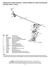
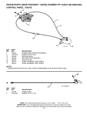
...IN THE BAG OF ITEMS SHIPPED LOOSE WITH PRODUCT. 2. NOTE: All component dimensions given in U.S. REPAIR PARTS SNOW THROWER - - inches. 1 inch = 25.4 mm IMPORTANT: Use only Original Equipment Manufacturer (O.E.M.) replacement parts. MODEL NUMBER PP1150E27 (96198003302) CONTROL PANEL / CHUTE 5 7 15 3 16 *14 *11 2 4 6 *10... 6 KEY NO. 1 2 3 4 5 6 7 8 9 *10 *11 *12 *13 *14 15 16 PART NO. 435023X428 178633X428 420673 420325 414280...
...IN THE BAG OF ITEMS SHIPPED LOOSE WITH PRODUCT. 2. NOTE: All component dimensions given in U.S. REPAIR PARTS SNOW THROWER - - inches. 1 inch = 25.4 mm IMPORTANT: Use only Original Equipment Manufacturer (O.E.M.) replacement parts. MODEL NUMBER PP1150E27 (96198003302) CONTROL PANEL / CHUTE 5 7 15 3 16 *14 *11 2 4 6 *10... 6 KEY NO. 1 2 3 4 5 6 7 8 9 *10 *11 *12 *13 *14 15 16 PART NO. 435023X428 178633X428 420673 420325 414280...
User Manual
Page 27
MODEL NUMBER PP1150E27 (96198003302) CONTROL PANEL / CHUTE 2 2 *3 1 *7 *6 *4 01.09.010-B *5 KEY NO. 1 2 *3 *4 *5 *6 *7 PART NO. 428272 17501010 420678 405932 420675 428273 428310 DESCRIPTION LEVER/CABLE ROTATOR ASSEMBLY SCREW 10-24 X .625 ROTATOR ...BRACKET PULLEY PIVOT CABLE ASSEMBLY ADJUSTABLE CABLE ASSEMBLY HEAT SHIELD NOTES: 1. inches. 1 inch = 25.4 mm IMPORTANT: Use only Original Equipment Manufacturer (O.E.M.) replacement parts. NO. DESCRIPTION 1 421249 STEER CABLE 2 74041024 SCREW 10−24 X 1.50 01.15.009-A NOTE: All component dimensions given in U.S. Failure ...
MODEL NUMBER PP1150E27 (96198003302) CONTROL PANEL / CHUTE 2 2 *3 1 *7 *6 *4 01.09.010-B *5 KEY NO. 1 2 *3 *4 *5 *6 *7 PART NO. 428272 17501010 420678 405932 420675 428273 428310 DESCRIPTION LEVER/CABLE ROTATOR ASSEMBLY SCREW 10-24 X .625 ROTATOR ...BRACKET PULLEY PIVOT CABLE ASSEMBLY ADJUSTABLE CABLE ASSEMBLY HEAT SHIELD NOTES: 1. inches. 1 inch = 25.4 mm IMPORTANT: Use only Original Equipment Manufacturer (O.E.M.) replacement parts. NO. DESCRIPTION 1 421249 STEER CABLE 2 74041024 SCREW 10−24 X 1.50 01.15.009-A NOTE: All component dimensions given in U.S. Failure ...
User Manual
Page 28
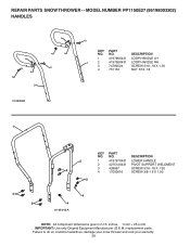
... LH 1 2 419799X431 LOOP HANDLE RH 3 74780524 SCREW 5/16−18 X 1.50 4 751153 NUT 5/16−18 1 2 4 KEY NO. 1 2 3 4 PART NO. 419797X431 427513X431 428867 17000616 DESCRIPTION LOWER HANDLE PIVOT SUPPORT WELDMENT SCREW 5/16−18 X .750 SCREW 3/8−16 X 1.00 3 4 3 4 4 01-05-013...-A NOTE: All component dimensions given in U.S. NO. inches. 1 inch = 25.4 mm IMPORTANT: Use only Original Equipment Manufacturer (O.E.M.) replacement parts. REPAIR PARTS SNOW THROWER - - MODEL NUMBER PP1150E27 (96198003302) HANDLES 4 4 3 2 01.08.004-B 3 4 4 3 3 KEY...
... LH 1 2 419799X431 LOOP HANDLE RH 3 74780524 SCREW 5/16−18 X 1.50 4 751153 NUT 5/16−18 1 2 4 KEY NO. 1 2 3 4 PART NO. 419797X431 427513X431 428867 17000616 DESCRIPTION LOWER HANDLE PIVOT SUPPORT WELDMENT SCREW 5/16−18 X .750 SCREW 3/8−16 X 1.00 3 4 3 4 4 01-05-013...-A NOTE: All component dimensions given in U.S. NO. inches. 1 inch = 25.4 mm IMPORTANT: Use only Original Equipment Manufacturer (O.E.M.) replacement parts. REPAIR PARTS SNOW THROWER - - MODEL NUMBER PP1150E27 (96198003302) HANDLES 4 4 3 2 01.08.004-B 3 4 4 3 3 KEY...


