

English Manual
Page 3
... at any commercial, rental or institutional setting. 14. If you use . 16. This is especially important for normal use the weight bench. Always fold the backrest out of the way when performing squat exercises (see page 14). 17. Do not stand with pre-existing health...with the leg lever (see page 15). When performing an exercise during which you are sitting on the weight rests. When you are performing bench press exercises, squat exercises or toe raise exercises, your back and the weight carriage. WARNING: Before beginning this manual. 13. Inspect and tighten...
... at any commercial, rental or institutional setting. 14. If you use . 16. This is especially important for normal use the weight bench. Always fold the backrest out of the way when performing squat exercises (see page 14). 17. Do not stand with pre-existing health...with the leg lever (see page 15). When performing an exercise during which you are sitting on the weight rests. When you are performing bench press exercises, squat exercises or toe raise exercises, your back and the weight carriage. WARNING: Before beginning this manual. 13. Inspect and tighten...

English Manual
Page 6
...the information in the drawings. Assembly Before beginning assembly, carefully read the following tools (not included) are required for Yourself! Assembly will take time. Press a 2Ó Square Inner Cap (17) into the top of the Stabilizer there is a sophisticated product with four M10 Nylon Locknuts (11). ... the Right Stabilizer (26). Most people find that this side.) Place the right Stabilizer flat on page 5. ¥ As you assemble the weight bench, make sure you have the following tools: A socket set, a set of open-end or closed-end wrenches or a set of the Right...
...the information in the drawings. Assembly Before beginning assembly, carefully read the following tools (not included) are required for Yourself! Assembly will take time. Press a 2Ó Square Inner Cap (17) into the top of the Stabilizer there is a sophisticated product with four M10 Nylon Locknuts (11). ... the Right Stabilizer (26). Most people find that this side.) Place the right Stabilizer flat on page 5. ¥ As you assemble the weight bench, make sure you have the following tools: A socket set, a set of open-end or closed-end wrenches or a set of the Right...

English Manual
Page 7
... up through the Left Stabilizer (25). Insert two M10 x 68mm Bolts (34) into the indi- Next, insert the Bolts into an Upright 3 Support Plate (16). Press a 38mm Square Inner Cap (31) into each end of the Left Upright (37). Attach the Crossbar (20) to the Left Upright (37) in the same... manner. 34 16 25 33 33 37 11 20 11 Decal 11 11 16 34 7 Press a 2Ó Square Inner Cap (17) into the vertical tube on the Left Stabilizer. 2. Press a 51mm x 76mm Inner Cap (53) into the top of the Left Stabilizer (25). Note: Make sure the adjustment...
... up through the Left Stabilizer (25). Insert two M10 x 68mm Bolts (34) into the indi- Next, insert the Bolts into an Upright 3 Support Plate (16). Press a 38mm Square Inner Cap (31) into each end of the Left Upright (37). Attach the Crossbar (20) to the Left Upright (37) in the same... manner. 34 16 25 33 33 37 11 20 11 Decal 11 11 16 34 7 Press a 2Ó Square Inner Cap (17) into the vertical tube on the Left Stabilizer. 2. Press a 51mm x 76mm Inner Cap (53) into the top of the Left Stabilizer (25). Note: Make sure the adjustment...

English Manual
Page 8
... (43), two M8 Washers (23), the Leg Lever Spacer (50), and an M8 Nylon Locknut (13). 17 39 18 13 50 17 17 23 43 7. Press the Angle Cap (49) onto the indicated end of the Weight Tube. Do not overtighten the Nylon Locknut. Insert two M10 x 68mm Bolts (34) through... then through 5. 11 5 59 34 20 6. Lubricate an M10 x 75mm Bolt (60). Insert two M10 x 68mm Bolts (34) into a Crossbar 5 Support Plate (59). Attach the Bench Frame with an M10 Nylon Locknut (11). Secure the upper M10 x 68mm Bolt (34) with two M10 Nylon Locknuts (11). Attach the Leg Lever (18...
... (43), two M8 Washers (23), the Leg Lever Spacer (50), and an M8 Nylon Locknut (13). 17 39 18 13 50 17 17 23 43 7. Press the Angle Cap (49) onto the indicated end of the Weight Tube. Do not overtighten the Nylon Locknut. Insert two M10 x 68mm Bolts (34) through... then through 5. 11 5 59 34 20 6. Lubricate an M10 x 75mm Bolt (60). Insert two M10 x 68mm Bolts (34) into a Crossbar 5 Support Plate (59). Attach the Bench Frame with an M10 Nylon Locknut (11). Secure the upper M10 x 68mm Bolt (34) with two M10 Nylon Locknuts (11). Attach the Leg Lever (18...

English Manual
Page 9
...x 38mm Screws (4) used in the adjustment brackets. 55 29 Pin Adjustment Brackets 37 55 9. Do not tighten the Screw yet. Press a 30mm Square Inner Cap (55) into the Bench Frame (5) until the tip is barely visible on the 6 other end of adjust- ment brackets on the Adjustment Tube (29). Secure... the Bolt with an M6 x 63mm Screw (7) and an M6 Washer (30). Press 1Ó Square Inner Caps (28) into the slots in...
...x 38mm Screws (4) used in the adjustment brackets. 55 29 Pin Adjustment Brackets 37 55 9. Do not tighten the Screw yet. Press a 30mm Square Inner Cap (55) into the Bench Frame (5) until the tip is barely visible on the 6 other end of adjust- ment brackets on the Adjustment Tube (29). Secure... the Bolt with an M6 x 63mm Screw (7) and an M6 Washer (30). Press 1Ó Square Inner Caps (28) into the slots in...

English Manual
Page 10
... x 68mm Bolt (34), two M10 Washers (6), two Pulley Spacers (41), and an M10 Nylon Locknut (11). Press a 2Ó Square Inner Cap (17) into the bracket on the Weight Carriage (47) from the direction shown...x 19mm Bolt (46) into the top of the 41 Lat Tower (9). 11 6 35 41 9 14. Press the last Carriage Bushing (2) into the indicated holes in the Lat Tower 34 6 (9) with the loop through ...on the other end. Locate the Cable (45) and note that it has a loop on the Weight Carriage. Press a 1Ó Round Inner Cap (12) into each Pad Tube (38) into the Carriage Stop (24) as...
... x 68mm Bolt (34), two M10 Washers (6), two Pulley Spacers (41), and an M10 Nylon Locknut (11). Press a 2Ó Square Inner Cap (17) into the bracket on the Weight Carriage (47) from the direction shown...x 19mm Bolt (46) into the top of the 41 Lat Tower (9). 11 6 35 41 9 14. Press the last Carriage Bushing (2) into the indicated holes in the Lat Tower 34 6 (9) with the loop through ...on the other end. Locate the Cable (45) and note that it has a loop on the Weight Carriage. Press a 1Ó Round Inner Cap (12) into each Pad Tube (38) into the Carriage Stop (24) as...
English Manual
Page 12
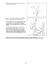
... holes lower than the Weight Rests (21, 58). 58 32 57 19. 17. Press a 1Ó Round Inner Cap (32) into one set of adjustment holes in the Uprights (1, 37). The use the weight bench. Make sure that they are hooked around the Uprights. Make sure that all remaining parts... will be explained in ADJUSTING THE WEIGHT BENCH, beginning on the next page. 12 Turn the Safety Spotters until the locking...
... holes lower than the Weight Rests (21, 58). 58 32 57 19. 17. Press a 1Ó Round Inner Cap (32) into one set of adjustment holes in the Uprights (1, 37). The use the weight bench. Make sure that they are hooked around the Uprights. Make sure that all remaining parts... will be explained in ADJUSTING THE WEIGHT BENCH, beginning on the next page. 12 Turn the Safety Spotters until the locking...


