

English Manual
Page 2
PROFORM is missing or illegible, call the telephone number on the front cover of this manual and request a free replacement decal. Note: The decals may not be shown at actual size. TABLE OF CONTENTS WARNING DECAL PLACEMENT 2 IMPORTANT PRECAUTIONS 3 BEFORE YOU BEGIN 7 PART IDENTIFICATION CHART 8 ASSEMBLY... 9 THE CHEST HEART RATE MONITOR 20 HOW TO USE THE TREADMILL 21 HOW TO FOLD AND MOVE THE TREADMILL 31 MAINTENANCE AND TROUBLESHOOTING 32 EXERCISE GUIDELINES 35 PART LIST 38 EXPLODED DRAWING...
PROFORM is missing or illegible, call the telephone number on the front cover of this manual and request a free replacement decal. Note: The decals may not be shown at actual size. TABLE OF CONTENTS WARNING DECAL PLACEMENT 2 IMPORTANT PRECAUTIONS 3 BEFORE YOU BEGIN 7 PART IDENTIFICATION CHART 8 ASSEMBLY... 9 THE CHEST HEART RATE MONITOR 20 HOW TO USE THE TREADMILL 21 HOW TO FOLD AND MOVE THE TREADMILL 31 MAINTENANCE AND TROUBLESHOOTING 32 EXERCISE GUIDELINES 35 PART LIST 38 EXPLODED DRAWING...

English Manual
Page 4
... speeds. able to safely lift 45 lbs. (20 kg) to move the treadmill. 26. Never leave the treadmill unattended while it is properly assembled. (See ASSEMBLY on page 9 and HOW TO FOLD AND MOVE THE TREADMILL on page 31.) You must be performed by an authorized ser- Servicing other than the procedures in this manual should...
... speeds. able to safely lift 45 lbs. (20 kg) to move the treadmill. 26. Never leave the treadmill unattended while it is properly assembled. (See ASSEMBLY on page 9 and HOW TO FOLD AND MOVE THE TREADMILL on page 31.) You must be performed by an authorized ser- Servicing other than the procedures in this manual should...
English Manual
Page 8
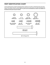
... below to see whether it is preattached. The number in the hardware kit, check to identify small parts used for assembly. The number following the key number is the quantity used for assembly. PART IDENTIFICATION CHART Use the drawings below each drawing is the key number of the part, from the PART...
... below to see whether it is preattached. The number in the hardware kit, check to identify small parts used for assembly. The number following the key number is the quantity used for assembly. PART IDENTIFICATION CHART Use the drawings below each drawing is the key number of the part, from the PART...
English Manual
Page 9
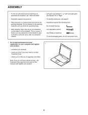
... your warranty • saves you time if you ever need to contact Customer Care • allows us to assemble the treadmill, call Customer Care (see page 8. • Assembly requires the following tools: the included hex key one adjustable wrench one Phillips screwdriver To avoid damaging parts, do ...not have internet access, call 1-800-445-2480 • Assembly requires two persons. • Place all assembly steps. • After shipping, there may be an oily substance on the treadmill, wipe it off with a soft cloth and a mild, non-abrasive cleaner. •...
... your warranty • saves you time if you ever need to contact Customer Care • allows us to assemble the treadmill, call Customer Care (see page 8. • Assembly requires the following tools: the included hex key one adjustable wrench one Phillips screwdriver To avoid damaging parts, do ...not have internet access, call 1-800-445-2480 • Assembly requires two persons. • Place all assembly steps. • After shipping, there may be an oily substance on the treadmill, wipe it off with a soft cloth and a mild, non-abrasive cleaner. •...
English Manual
Page 14
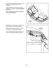
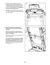
... insert it into the gap indicated by the arrow. 99 31 Console Assembly 99 D 99 86 99 14 do not overtighten the Screws. Then, remove and save the four indicated 1/4" x 1/2" Screws (31). 10 1 31 36 1 1 27 1 Console Assembly 11. Attach the Right and Left Trays (27, 36) with eight... #8 x 1/2" Screws (1); With the help of a second person, hold the console assembly near the left Handrail (86). 11 Make sure that the pulse wire (D) is inserted ...
... insert it into the gap indicated by the arrow. 99 31 Console Assembly 99 D 99 86 99 14 do not overtighten the Screws. Then, remove and save the four indicated 1/4" x 1/2" Screws (31). 10 1 31 36 1 1 27 1 Console Assembly 11. Attach the Right and Left Trays (27, 36) with eight... #8 x 1/2" Screws (1); With the help of a second person, hold the console assembly near the left Handrail (86). 11 Make sure that the pulse wire (D) is inserted ...
English Manual
Page 15
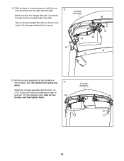
... 99 81 99 13. Then, route the Upright Wire (81) as shown, and insert it into the gap indicated by the arrow. Attach the console assembly with the four 1/4" x 1/2" Screws (31) that the Upright Wire (81) is inserted through the three looped Cable Ties (99). start all four 86 Screws, and... then tighten them. With the help of a second person, hold the console assembly near the right Handrail (86). 12 Make sure that you removed in step 10 and four 1/4" Star Washers (32); Be careful not to pinch any...
... 99 81 99 13. Then, route the Upright Wire (81) as shown, and insert it into the gap indicated by the arrow. Attach the console assembly with the four 1/4" x 1/2" Screws (31) that the Upright Wire (81) is inserted through the three looped Cable Ties (99). start all four 86 Screws, and... then tighten them. With the help of a second person, hold the console assembly near the right Handrail (86). 12 Make sure that you removed in step 10 and four 1/4" Star Washers (32); Be careful not to pinch any...

English Manual
Page 17
... Slot the Console Base Back. Attach the Console Cover (105) with two #8 x 3/4" Screws (2). 17 105 2 82 7 83 7 17 Slot Tighten ten #8 x 3/4" Screws (2) into the handrail assembly. The speaker wires (H) need to the handrail assem- 16 bly (I). Slide the Console Base Back (104) upward to fit into the handrail...
... Slot the Console Base Back. Attach the Console Cover (105) with two #8 x 3/4" Screws (2). 17 105 2 82 7 83 7 17 Slot Tighten ten #8 x 3/4" Screws (2) into the handrail assembly. The speaker wires (H) need to the handrail assem- 16 bly (I). Slide the Console Base Back (104) upward to fit into the handrail...
English Manual
Page 18
... (56) to the brackets on a smooth surface, it may roll forward during 19 this step. Have a second person hold the Frame until step 21 is assembled on the Frame (56) with the four 5/16" x 3/4" Screws (4) that the "This side toward belt" sticker (J) is facing away from the Latch ...Left and Right Base Covers (82, 83) into place. 11 4 90 41 4 11 89 19. Tighten the six 3/8" x 4" Screws (7). 18. Note: If the treadmill is completed. Carefully slide the Upright Crossbar (41) 18 between the Left and Right Uprights (89, 90). Attach the Latch Crossbar to the upright position...
... (56) to the brackets on a smooth surface, it may roll forward during 19 this step. Have a second person hold the Frame until step 21 is assembled on the Frame (56) with the four 5/16" x 3/4" Screws (4) that the "This side toward belt" sticker (J) is facing away from the Latch ...Left and Right Base Covers (82, 83) into place. 11 4 90 41 4 11 89 19. Tighten the six 3/8" x 4" Screws (7). 18. Note: If the treadmill is completed. Carefully slide the Upright Crossbar (41) 18 between the Left and Right Uprights (89, 90). Attach the Latch Crossbar to the upright position...


