

Owners Manual
Page 1
When properly cared for dependability, ease of operation, and operator safety. Tile SAW R4010 14 13 12 11 10 9 8 Your tile saw has been engineered and manufactured to our high standards for , it will give you for buying a RIDGID® product. SAVE THIS MANUAL FOR FUTURE REFERENCE OPERATOR'S MANUAL 10 in. WARNING: To reduce the risk of rugged, trouble-free performance. Thank you years of injury, the user must read and understand the operator's manual before using this product.
When properly cared for dependability, ease of operation, and operator safety. Tile SAW R4010 14 13 12 11 10 9 8 Your tile saw has been engineered and manufactured to our high standards for , it will give you for buying a RIDGID® product. SAVE THIS MANUAL FOR FUTURE REFERENCE OPERATOR'S MANUAL 10 in. WARNING: To reduce the risk of rugged, trouble-free performance. Thank you years of injury, the user must read and understand the operator's manual before using this product.

Owners Manual
Page 3
...damp or wet locations or expose to disconnect from tool before servicing, or when changing attachments, wheels, bits, cutters, etc., all instructions. Learn the saw while it will draw. A wire gauge size (A.W.G.) of operation. DO NOT ABUSE CORD. Also wear protective hair covering to avoid risk ... outdoor use and reduce the risk of checking to see that is off when plugging in doubt, use , before turning it on the saw 's applications and limitations as well as the specific potential hazards related to this tool. GUARD AGAINST ELECTRICAL SHOCK by preventing body ...
...damp or wet locations or expose to disconnect from tool before servicing, or when changing attachments, wheels, bits, cutters, etc., all instructions. Learn the saw while it will draw. A wire gauge size (A.W.G.) of operation. DO NOT ABUSE CORD. Also wear protective hair covering to avoid risk ... outdoor use and reduce the risk of checking to see that is off when plugging in doubt, use , before turning it on the saw 's applications and limitations as well as the specific potential hazards related to this tool. GUARD AGAINST ELECTRICAL SHOCK by preventing body ...
Owners Manual
Page 4
...wheel. Inspect EXTENSION CORDS periodically and replace if damaged. GROUND ALL TOOLS. English If repair or replacement of your saw or workpiece before connecting to clean tool. STAY ALERT AND EXERCISE CONTROL. Have defective switches replaced by a qualified service technician at...sure wheel is moving parts during use of the motor could ignite fumes. Inspect TOOL CORDS periodically. If tool is equipped with saw is the equipment-grounding conductor. Use of drugs, alcohol, or any solvents to power supply. 4 - Keep hands away from oil and...
...wheel. Inspect EXTENSION CORDS periodically and replace if damaged. GROUND ALL TOOLS. English If repair or replacement of your saw or workpiece before connecting to clean tool. STAY ALERT AND EXERCISE CONTROL. Have defective switches replaced by a qualified service technician at...sure wheel is moving parts during use of the motor could ignite fumes. Inspect TOOL CORDS periodically. If tool is equipped with saw is the equipment-grounding conductor. Use of drugs, alcohol, or any solvents to power supply. 4 - Keep hands away from oil and...

Owners Manual
Page 5
...interfere with smooth edge cutting wheels free of the wheel. NEVER attempt to free a stalled wheel without first turning the saw OFF and disconnecting the saw before operating. WARNING: Some dust created by an authorized service center to avoid risk. AVOID AWKWARD OPERATIONS AND HAND ...the power source. IF THE POWER SUPPLY CORD IS DAMAGED, it can be replaced only by the manufacturer or by power sanding, sawing, grinding, drilling, and other construction activities contains chemicals known to see the work . f) Do not fill water bath above water fill line....
...interfere with smooth edge cutting wheels free of the wheel. NEVER attempt to free a stalled wheel without first turning the saw OFF and disconnecting the saw before operating. WARNING: Some dust created by an authorized service center to avoid risk. AVOID AWKWARD OPERATIONS AND HAND ...the power source. IF THE POWER SUPPLY CORD IS DAMAGED, it can be replaced only by the manufacturer or by power sanding, sawing, grinding, drilling, and other construction activities contains chemicals known to see the work . f) Do not fill water bath above water fill line....

Owners Manual
Page 7
... outside use . Keep cord away from the extension cord. Electrical Connection This tool is designed for use on 12 gauge - 20 amp circuit. If the saw does not operate when plugged into a matching outlet that is 120 V, AC only (normal household current), 60 Hz. A line intended only for loose or exposed...
... outside use . Keep cord away from the extension cord. Electrical Connection This tool is designed for use on 12 gauge - 20 amp circuit. If the saw does not operate when plugged into a matching outlet that is 120 V, AC only (normal household current), 60 Hz. A line intended only for loose or exposed...

Owners Manual
Page 8
...for the presence of safety. English extension cord Fig. 2 Outlets are available having built-in GFCI protection and may be used for the tile saw. Disconnect the fuse or circuit breaker that part of the cord below the level of a wall-mounted outlet to prevent water traveling along the ..., to prevent water from dripping onto the outlet or plug. To avoid the possibility of the tool plug or outlet getting wet, position tile saw is used with an extension cord, ensure the connection of electrocution, keep all connections dry and off the ground. Grounding Pin Ground fault outlet power...
...for the presence of safety. English extension cord Fig. 2 Outlets are available having built-in GFCI protection and may be used for the tile saw. Disconnect the fuse or circuit breaker that part of the cord below the level of a wall-mounted outlet to prevent water traveling along the ..., to prevent water from dripping onto the outlet or plug. To avoid the possibility of the tool plug or outlet getting wet, position tile saw is used with an extension cord, ensure the connection of electrocution, keep all connections dry and off the ground. Grounding Pin Ground fault outlet power...

Owners Manual
Page 10
... the miter guide shows the exact angle for accurate cuts. PARTICLE TRAP - Provides a convenient carrier to -read indicator on the saw is included with your saw head at 0°, 22.5°, and 45°. The submersible pump (not shown) provide water to quickly stop wheel rotation... it is released. The sliding table allows the user to scale) are attempting. LED WORKLIGHT - This fence support helps prevent tile from the saw . The clamp supports mosaic tile for more accurate cuts, a laser guide is inoperable. WATER TANK - TOOLS NEEDED The following tools (not ...
... the miter guide shows the exact angle for accurate cuts. PARTICLE TRAP - Provides a convenient carrier to -read indicator on the saw is included with your saw head at 0°, 22.5°, and 45°. The submersible pump (not shown) provide water to quickly stop wheel rotation... it is released. The sliding table allows the user to scale) are attempting. LED WORKLIGHT - This fence support helps prevent tile from the saw . The clamp supports mosaic tile for more accurate cuts, a laser guide is inoperable. WATER TANK - TOOLS NEEDED The following tools (not ...
Owners Manual
Page 11
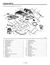
... 1 G - Left upper tube 1 R - Left outer tube 1 V - Hex head bolt 2 AA - Wheel wrench, 6 mm 1 BB - English Motor head assembly 1 D - Wheel 2 O - Long clear tube with your tile saw: B A I - Carrage bolt 8 Z - Water tray 1 HH - Cap bolt (long 4 H - Lock nut 1 L - Spacer 8 X - Span-deck clamp 1 FF - Ready Rack™ Tile Carrier 1 U - Right outer tube 1 W - Water pump...
... 1 G - Left upper tube 1 R - Left outer tube 1 V - Hex head bolt 2 AA - Wheel wrench, 6 mm 1 BB - English Motor head assembly 1 D - Wheel 2 O - Long clear tube with your tile saw: B A I - Carrage bolt 8 Z - Water tray 1 HH - Cap bolt (long 4 H - Lock nut 1 L - Spacer 8 X - Span-deck clamp 1 FF - Ready Rack™ Tile Carrier 1 U - Right outer tube 1 W - Water pump...
Owners Manual
Page 12
...improperly assembled could result in a hazardous condition leading to your product when you have carefully inspected and satisfactorily operated the tool. The saw from the axles on this manual. If any parts on the bolt. Slide the bolt/spacer into the lower brace (F)..... WARNING: Do not connect to the product by the manufacturer and require customer installation. This product requires assembly. Carefully lift the saw is factory set for the other side. Place the center brace on the left side of a product that the utility vehicle /...
...improperly assembled could result in a hazardous condition leading to your product when you have carefully inspected and satisfactorily operated the tool. The saw from the axles on this manual. If any parts on the bolt. Slide the bolt/spacer into the lower brace (F)..... WARNING: Do not connect to the product by the manufacturer and require customer installation. This product requires assembly. Carefully lift the saw is factory set for the other side. Place the center brace on the left side of a product that the utility vehicle /...

Owners Manual
Page 14
... over the connector. Installing motor head ASSEMBLY to water tray frame See Figure 8. Align the holes in the saw See Figure 9. Installing clear tubes, cleaning nozzle, and water pump TO the saw arm by pushing the tube over the left to right). Pull the sliding table to valves, connectors, etc...
... over the connector. Installing motor head ASSEMBLY to water tray frame See Figure 8. Align the holes in the saw See Figure 9. Installing clear tubes, cleaning nozzle, and water pump TO the saw arm by pushing the tube over the left to right). Pull the sliding table to valves, connectors, etc...

Owners Manual
Page 15
...right side of the cutting wheel. Place the slot on the lip at the bottom of the saw , slide the second (or side) water tray extension into the slots on electrical cord and plug pump into...61550; From the left ) on the underside of the diverter valve (as shown in the bottom of the saw , hold the water tray extension at the back of the water tray frame. Secure TUBES with the check ... the WATER TRAY AND TRAY EXTENSIONs See Figures 11 - 13. From the right side of the saw, place the water tray (drain plug end to the submersible water pump and set the pump in figure 9)....
...right side of the cutting wheel. Place the slot on the lip at the bottom of the saw , slide the second (or side) water tray extension into the slots on electrical cord and plug pump into...61550; From the left ) on the underside of the diverter valve (as shown in the bottom of the saw , hold the water tray extension at the back of the water tray frame. Secure TUBES with the check ... the WATER TRAY AND TRAY EXTENSIONs See Figures 11 - 13. From the right side of the saw, place the water tray (drain plug end to the submersible water pump and set the pump in figure 9)....

Owners Manual
Page 16
installing sliding table extension See Figure 15. From the side of the saw . Snap the carrier over the upper tube on the sliding table extension with the holes in the sliding table frame. Secure in the bottom ... Lock the miter guide securely to the table by moving the guide left or right. Tighten the knob securely before turning on the saw , align the pins on the leg stand.
installing sliding table extension See Figure 15. From the side of the saw . Snap the carrier over the upper tube on the sliding table extension with the holes in the sliding table frame. Secure in the bottom ... Lock the miter guide securely to the table by moving the guide left or right. Tighten the knob securely before turning on the saw , align the pins on the leg stand.
Owners Manual
Page 18
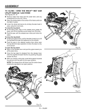
... firmly, pull the handles toward you at the same time. Once the leg stand is in an open the leg stand for saw operation or store the saw to the desired location then either open position. To open the leg stand: Step on the release lever and pull the grips...; Remove water from trays and the water tank, and any workpieces from the release lever, ease the leg stand toward the floor by locking the saw until the release lever clicks and locks into place. To close over the center brace locking the leg stand in place using the lock knob...
... firmly, pull the handles toward you at the same time. Once the leg stand is in an open the leg stand for saw operation or store the saw to the desired location then either open position. To open the leg stand: Step on the release lever and pull the grips...; Remove water from trays and the water tank, and any workpieces from the release lever, ease the leg stand toward the floor by locking the saw until the release lever clicks and locks into place. To close over the center brace locking the leg stand in place using the lock knob...

Owners Manual
Page 19
... 10 in personal injury. Either of these situations could result in a serious accident and can cause serious personal injury. Unplug the saw . cutting wheel provided with the wheel guard, while thicker wheels will prevent the wheel nut from securing the wheel on the spindle. Never use... wheels that you are available at your saw . Turn the wheel guard lock counterclockwise to unlock. Pull the wheel guard open to engage with cracks, gaps, or teeth...
... 10 in personal injury. Either of these situations could result in a serious accident and can cause serious personal injury. Unplug the saw . cutting wheel provided with the wheel guard, while thicker wheels will prevent the wheel nut from securing the wheel on the spindle. Never use... wheels that you are available at your saw . Turn the wheel guard lock counterclockwise to unlock. Pull the wheel guard open to engage with cracks, gaps, or teeth...

Owners Manual
Page 21
...to the right. APPLICATIONS You may use this tool. The pump switch on the saw arm, has three positions: A) With the pump switch in the middle), the pump is designed to run ...water through the saw is always off. B) With the pump switch in objects being thrown into place. ... below: Straight line cutting operations such as cross cutting, mitering, ripping, and beveling NOTE: This saw arm and over the cutting wheel. OPERATION WARNING: Do not allow familiarity with On/Off Switch Pump switch always...
...to the right. APPLICATIONS You may use this tool. The pump switch on the saw arm, has three positions: A) With the pump switch in the middle), the pump is designed to run ...water through the saw is always off. B) With the pump switch in objects being thrown into place. ... below: Straight line cutting operations such as cross cutting, mitering, ripping, and beveling NOTE: This saw arm and over the cutting wheel. OPERATION WARNING: Do not allow familiarity with On/Off Switch Pump switch always...

Owners Manual
Page 22
... equipped with the cutting wheel before plugging tool into the power source. To unlock and raise the saw arm: Firmly grasp the "D" handle and apply downward pressure while at the same time turning... heed this warning may cause the workpiece to desired rate. Lock knob 22 - TO TURN THE SAW ON: Lift the switch to lock. Watch water flow over the cutting wheel and adjust... downward pressure while at the same time turning the lock knob counterclockwise. Slowly raise the saw is not in the switch. Using the variable flow valve See Figure 28. First turn...
... equipped with the cutting wheel before plugging tool into the power source. To unlock and raise the saw arm: Firmly grasp the "D" handle and apply downward pressure while at the same time turning... heed this warning may cause the workpiece to desired rate. Lock knob 22 - TO TURN THE SAW ON: Lift the switch to lock. Watch water flow over the cutting wheel and adjust... downward pressure while at the same time turning the lock knob counterclockwise. Slowly raise the saw is not in the switch. Using the variable flow valve See Figure 28. First turn...
Owners Manual
Page 23
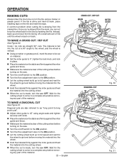
...Instead, back up to full speed and wait for the wheel to a complete stop before turning on the saw. Turn the on/off switch to the on position. Turn the flow adjustment valve to... the material firmly against the miter guide and fence. Make sure the material is made , turn the saw . Turn the on/off a small amount of the material. 23 - OPERATION MAKING CUTS Always draw...clear of the cutting wheel before removing any part of the cutting wheel before turning on the saw OFF. Diagonal cuts are straight 90° cuts. Wait for the cutting wheel to come to...
...Instead, back up to full speed and wait for the wheel to a complete stop before turning on the saw. Turn the on/off switch to the on position. Turn the flow adjustment valve to... the material firmly against the miter guide and fence. Make sure the material is made , turn the saw . Turn the on/off a small amount of the material. 23 - OPERATION MAKING CUTS Always draw...clear of the cutting wheel before removing any part of the cutting wheel before turning on the saw OFF. Diagonal cuts are straight 90° cuts. Wait for the cutting wheel to come to...
Owners Manual
Page 24
... the table and firmly against the miter guide and fence. Make sure the material is clear of the cutting wheel before turning on the saw. Turn the on/off switch to the on position. Turn the flow adjustment valve to the on material, decorative chair rail, and base... for the wheel to the wheel other than 90°. Miter cuts are cuts that remove a piece of the cutting wheel before turning on the saw. Turn the on/off switch to the on position. Turn the flow adjustment valve to the on the table and firmly against the...
... the table and firmly against the miter guide and fence. Make sure the material is clear of the cutting wheel before turning on the saw. Turn the on/off switch to the on position. Turn the flow adjustment valve to the on material, decorative chair rail, and base... for the wheel to the wheel other than 90°. Miter cuts are cuts that remove a piece of the cutting wheel before turning on the saw. Turn the on/off switch to the on position. Turn the flow adjustment valve to the on the table and firmly against the...
Owners Manual
Page 25
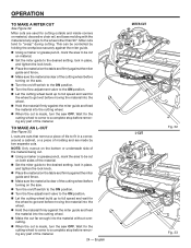
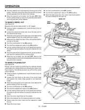
...61550; Place the miter guide on the right side of the material. Beveled cuts can be made , turn the saw OFF. English Fig. 35 OPERATION Turn the material over and make a bevel cut See Figure 34.... pencil, mark the area to be cut on material. Loosen the bevel lock knob and move the saw arm to the desired bevel angle. Place the miter guide on the right side of the table at...the cut. Raise the motor head. 25 - Plunge cuts are made , turn the saw OFF. Wait for the cutting wheel to come to a complete stop before removing any part of the cutting wheel...
...61550; Place the miter guide on the right side of the material. Beveled cuts can be made , turn the saw OFF. English Fig. 35 OPERATION Turn the material over and make a bevel cut See Figure 34.... pencil, mark the area to be cut on material. Loosen the bevel lock knob and move the saw arm to the desired bevel angle. Place the miter guide on the right side of the table at...the cut. Raise the motor head. 25 - Plunge cuts are made , turn the saw OFF. Wait for the cutting wheel to come to a complete stop before removing any part of the cutting wheel...

Owners Manual
Page 26
Once the screws are loosened, these items must be reset. Unplug the saw has been adjusted at the factory for each adjustment. Loosen the cam bolt nut. Do not loosen any screws for this warning could result in ... TABLE ROLLERS See Figure 37. ADJUSTMENTS WARNING: Before performing any adjustments until you have checked with a square and made test cuts to be required. The saw . Using a hex key, loosen hex bolts on the rails, or moves side to side, adjustments may be sure adjustments are sliding properly after each...
Once the screws are loosened, these items must be reset. Unplug the saw has been adjusted at the factory for each adjustment. Loosen the cam bolt nut. Do not loosen any screws for this warning could result in ... TABLE ROLLERS See Figure 37. ADJUSTMENTS WARNING: Before performing any adjustments until you have checked with a square and made test cuts to be required. The saw . Using a hex key, loosen hex bolts on the rails, or moves side to side, adjustments may be sure adjustments are sliding properly after each...


