
Installation Instructions
Page 2
...may be responsible for additional instructions. When Installing... ...In a Ceiling or Wall Make sure the ceiling/wall is leaking. Provide snow vents. Escaped refrigerant gas, on a raised platform that is an important part of the flare and union tubes before opening the unit to provide added support...this document. 05-424 KS0971-1271 12/13/05 1:27 PM Page 2 IMPORTANT! CAUTION This symbol refers to reduce strain on the air conditioner can cause accidental injury or death. • Ground the unit following local electrical codes. • Connect all warning and caution notices ...
...may be responsible for additional instructions. When Installing... ...In a Ceiling or Wall Make sure the ceiling/wall is leaking. Provide snow vents. Escaped refrigerant gas, on a raised platform that is an important part of the flare and union tubes before opening the unit to provide added support...this document. 05-424 KS0971-1271 12/13/05 1:27 PM Page 2 IMPORTANT! CAUTION This symbol refers to reduce strain on the air conditioner can cause accidental injury or death. • Ground the unit following local electrical codes. • Connect all warning and caution notices ...

Installation Instructions
Page 3
...parts listed are with Unit Table 1 Parts Remote control unit Figure Q'ty 1 Parts Tapping screw Figure Truss-head Phillips 5/32 ¥ 5/8" (4¥16 mm) Q'ty 10 Parts...the outdoor unit to the indoor unit is available in the outdoor unit. 1 Air clean filter 2 Cushion rubber* 4 1-3. Deoxidized annealed copper tube for Installation ...instructions or limitations. Standard screwdriver 2. Torque wrench 14. Wall thickness of wiring. Tools Required for refrigerant tubing as required ... Insulation Material If you will need: 1. Drill 11. Wire size varies with the total length of ...
...parts listed are with Unit Table 1 Parts Remote control unit Figure Q'ty 1 Parts Tapping screw Figure Truss-head Phillips 5/32 ¥ 5/8" (4¥16 mm) Q'ty 10 Parts...the outdoor unit to the indoor unit is available in the outdoor unit. 1 Air clean filter 2 Cushion rubber* 4 1-3. Deoxidized annealed copper tube for Installation ...instructions or limitations. Standard screwdriver 2. Torque wrench 14. Wall thickness of wiring. Tools Required for refrigerant tubing as required ... Insulation Material If you will need: 1. Drill 11. Wire size varies with the total length of ...
Installation Instructions
Page 8
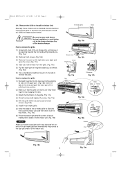
... the right side cover plate and open the cover. (Fig. 17a) (4) Take out the thermistor from the grille. (Fig. 17b) (5) Pull the lower part of the heat exchanger. Air intake grille Grille Fig. 16a Screw cover Cover Thermistor Fig. 16b Fig. 17a Tab * Thermistor Fig. 17b * Grille Frame Tab Fig. 18a * * Fig.... 18b) Insert the tabs in the slots and push the lower part of the grille back into position. (2) Make sure that the round pins at the top right and left corners of the air intake grille are inserted into the top of the indoor unit, and then insert it all the way...
... the right side cover plate and open the cover. (Fig. 17a) (4) Take out the thermistor from the grille. (Fig. 17b) (5) Pull the lower part of the heat exchanger. Air intake grille Grille Fig. 16a Screw cover Cover Thermistor Fig. 16b Fig. 17a Tab * Thermistor Fig. 17b * Grille Frame Tab Fig. 18a * * Fig.... 18b) Insert the tabs in the slots and push the lower part of the grille back into position. (2) Make sure that the round pins at the top right and left corners of the air intake grille are inserted into the top of the indoor unit, and then insert it all the way...

Installation Instructions
Page 9
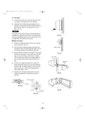
... 21) b) Right-rear or left-rear tubing In this case, the corner of the frame need not be cut. (2) To mount the indoor unit on the rear panel: Hang the 2 mounting slots of the unit on its nameplate, then carry out the wiring closely following the wiring diagram. (2) Provide a power outlet to... the unit as shown on the upper tabs of the fan. (6) Unauthorized changes in accordance with a power supply disconnect and circuit breaker for any moving parts of the rear panel. (Fig. 22) 3-6. Frame Left tubing outlet Fig. 20 Frame Right tubing outlet Fig. 21 Fig. 22 9 Wrong wiring may cause the...
... 21) b) Right-rear or left-rear tubing In this case, the corner of the frame need not be cut. (2) To mount the indoor unit on the rear panel: Hang the 2 mounting slots of the unit on its nameplate, then carry out the wiring closely following the wiring diagram. (2) Provide a power outlet to... the unit as shown on the upper tabs of the fan. (6) Unauthorized changes in accordance with a power supply disconnect and circuit breaker for any moving parts of the rear panel. (Fig. 22) 3-6. Frame Left tubing outlet Fig. 20 Frame Right tubing outlet Fig. 21 Fig. 22 9 Wrong wiring may cause the...
Installation Instructions
Page 10
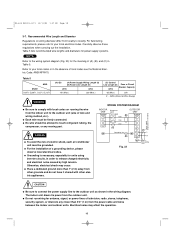
...be allowed to the outdoor unit (size of a grounding device, please observe local electrical codes. AWG (American Wire Gauge) Power supply Single phase 115V 60HZ WARNING q Be sure to comply with local codes on wiring diameter differ from the outdoor unit. q For the ...moving part. q Each wire must be firmly connected. Otherwise, electrical shock may affect the operation. 10 Carefully observe these regulations when carrying out the installation. Table 5 lists recommended wire lengths and diameters for antenna, signal, or power lines of electric shock, each air conditioner ...
...be allowed to the outdoor unit (size of a grounding device, please observe local electrical codes. AWG (American Wire Gauge) Power supply Single phase 115V 60HZ WARNING q Be sure to comply with local codes on wiring diameter differ from the outdoor unit. q For the ...moving part. q Each wire must be firmly connected. Otherwise, electrical shock may affect the operation. 10 Carefully observe these regulations when carrying out the installation. Table 5 lists recommended wire lengths and diameters for antenna, signal, or power lines of electric shock, each air conditioner ...
Installation Instructions
Page 13
... unit and then tape as far as the fittings. (See Caution on page 18.) The drain hose should come straight down the air discharge outlet and press the lower part of the indoor unit. (Fig. 34) s Right-side tubing (1) Shape the refrigerant tubing so that it can easily go into... tubing, and drain hose through the hole in Fig. 37b. Mounting (1) To install the indoor unit, mount the indoor unit onto the 2 tabs on the upper part of the rear plate. (2) Hold down the wall to a point where water runoff won't stain the wall. (4) Connect the refrigerant tubing to the outdoor unit. (After performing...
... unit and then tape as far as the fittings. (See Caution on page 18.) The drain hose should come straight down the air discharge outlet and press the lower part of the indoor unit. (Fig. 34) s Right-side tubing (1) Shape the refrigerant tubing so that it can easily go into... tubing, and drain hose through the hole in Fig. 37b. Mounting (1) To install the indoor unit, mount the indoor unit onto the 2 tabs on the upper part of the rear plate. (2) Hold down the wall to a point where water runoff won't stain the wall. (4) Connect the refrigerant tubing to the outdoor unit. (After performing...

Installation Instructions
Page 14
... drain cap. Then bend the tubing using a tube bender to push in, wet the cap with clamps. (Figs. 40a and 41) Hole in wall Rear panel Bent part Fig. 38 Wide tube Narrow tube Drain hose Fig. 39 Drain cap Drain cap Drain hose Clamp Fig. 40a Screw hole Drain pan outlet...-unit wiring 14 05-424 KS0971-1271 12/13/05 1:28 PM Page 14 s Left-side tubing (1) Lead the tubing and drain hose through the wall, allowing sufficient length for connection.
... drain cap. Then bend the tubing using a tube bender to push in, wet the cap with clamps. (Figs. 40a and 41) Hole in wall Rear panel Bent part Fig. 38 Wide tube Narrow tube Drain hose Fig. 39 Drain cap Drain cap Drain hose Clamp Fig. 40a Screw hole Drain pan outlet...-unit wiring 14 05-424 KS0971-1271 12/13/05 1:28 PM Page 14 s Left-side tubing (1) Lead the tubing and drain hose through the wall, allowing sufficient length for connection.

Installation Instructions
Page 15
... its equivalent is recommended. 05-424 KS0971-1271 12/13/05 1:28 PM Page 15 To unmount indoor unit Press the 2 v marks on the lower part of Electric Shock Push Fig. 42 Slant Indoor unit Drain hose Fig. 43 Condensation Insulation material (Locally purchased) must be slanted downward to the outside...
... its equivalent is recommended. 05-424 KS0971-1271 12/13/05 1:28 PM Page 15 To unmount indoor unit Press the 2 v marks on the lower part of Electric Shock Push Fig. 42 Slant Indoor unit Drain hose Fig. 43 Condensation Insulation material (Locally purchased) must be slanted downward to the outside...
Installation Instructions
Page 19
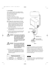
q pressure in the system rises q operating current rises q cooling (or heating) efficiency drops q moisture in the air may freeze and block capillary tubing q water may lead to corrosion of parts in Table 7 is around 10 mmHg abs. The valve core is similar to those used If tubing length is less than 33 ft... a manifold valve for R410A must be used. or more than 33 ft. (10 m) 10 min. NOTE The required time in the refrigerant system s Air Purging with a Vacuum Pump (for R410A) Pressure gauge Lo Hi CAUTION The service port on the wide tube service valve uses a Schrader core valve to...
q pressure in the system rises q operating current rises q cooling (or heating) efficiency drops q moisture in the air may freeze and block capillary tubing q water may lead to corrosion of parts in Table 7 is around 10 mmHg abs. The valve core is similar to those used If tubing length is less than 33 ft... a manifold valve for R410A must be used. or more than 33 ft. (10 m) 10 min. NOTE The required time in the refrigerant system s Air Purging with a Vacuum Pump (for R410A) Pressure gauge Lo Hi CAUTION The service port on the wide tube service valve uses a Schrader core valve to...
