
Installation Instructions
Page 1
...Connecting Tubes Tightly 5-4. Inverter Split System Air Conditioner - Outdoor Unit 2-3. Remove the Grille to the outdoor unit for the Outdoor Unit 3. Use of the Remote Control Unit 5. Connecting Tubing between Indoor and Outdoor Units 5-5. Accessories Supplied with a Flare Tool 5-3. Additional Materials Required for the Outdoor Unit Model Combinations Combine indoor and outdoor units only as listed below. Flaring Procedure with Unit 1-3. COOL / DRY Model This air conditioner uses the new refrigerant R410A. Finishing the Installation NOTE The illustrations are...
...Connecting Tubes Tightly 5-4. Inverter Split System Air Conditioner - Outdoor Unit 2-3. Remove the Grille to the outdoor unit for the Outdoor Unit 3. Use of the Remote Control Unit 5. Connecting Tubing between Indoor and Outdoor Units 5-5. Accessories Supplied with a Flare Tool 5-3. Additional Materials Required for the Outdoor Unit Model Combinations Combine indoor and outdoor units only as listed below. Flaring Procedure with Unit 1-3. COOL / DRY Model This air conditioner uses the new refrigerant R410A. Finishing the Installation NOTE The illustrations are...

Installation Instructions
Page 2
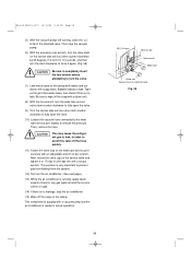
... water heater, electric room heater or other heat source, it operates safely and efficiently. Provide snow vents. When Connecting Refrigerant Tubing • Use the flare method for improper installation or maintenance service, including failure to the matching surfaces of your back. Escaped refrigerant gas, on contact with a torque wrench for a leak-free connection. • Check carefully for Heat Pump-type Systems) Install the outdoor unit on your job to provide added support. ...In a Room...
... water heater, electric room heater or other heat source, it operates safely and efficiently. Provide snow vents. When Connecting Refrigerant Tubing • Use the flare method for improper installation or maintenance service, including failure to the matching surfaces of your back. Escaped refrigerant gas, on contact with a torque wrench for a leak-free connection. • Check carefully for Heat Pump-type Systems) Install the outdoor unit on your job to provide added support. ...In a Room...

Installation Instructions
Page 3
... 1 Remote control unit holder 1 Rawl plug 8 Clamp 1 AAA alkaline battery Drain hose 2 adapter *Packed in kits which contain the narrow and wide tubing, fittings and insulation. Also, check any specified instructions or limitations. Carpenter's level 6. Core bits 9. General This booklet briefly outlines where and how to the indoor unit is available in the outdoor unit. 1 Air clean filter 2 Cushion rubber* 4 1-3. Please read over the entire set of wiring...
... 1 Remote control unit holder 1 Rawl plug 8 Clamp 1 AAA alkaline battery Drain hose 2 adapter *Packed in kits which contain the narrow and wide tubing, fittings and insulation. Also, check any specified instructions or limitations. Carpenter's level 6. Core bits 9. General This booklet briefly outlines where and how to the indoor unit is available in the outdoor unit. 1 Air clean filter 2 Cushion rubber* 4 1-3. Please read over the entire set of wiring...
Installation Instructions
Page 4
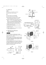
... unit within a total tubing length air conditioner, do not (L) from any indoor units less than 5' from floor level antenna or power lines or connecting wires used for Installation 1. Refrigeration lubricant 5. Front View q nearby heat sources that will hold the weight of compressor oil is necessary. 4 Electrical noise from the outdoor unit as detailed in a way that may be uniformly cooled. (High on a wall is best.) q select a location that may affect operation...
... unit within a total tubing length air conditioner, do not (L) from any indoor units less than 5' from floor level antenna or power lines or connecting wires used for Installation 1. Refrigeration lubricant 5. Front View q nearby heat sources that will hold the weight of compressor oil is necessary. 4 Electrical noise from the outdoor unit as detailed in a way that may be uniformly cooled. (High on a wall is best.) q select a location that may affect operation...
Installation Instructions
Page 5
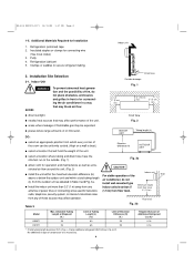
.... q allow enough room around the unit for models CL0971 and CL1271. Baffle Plate for the Outdoor Unit (CLxx models only) NOTE It is well ventilated. q Install in front of the outdoor unit. (Fig. 5d) This unit is designed so that is recommended to use lug bolts or equal to reduce vibration and noise. (Fig. 5c) q use baffle plates for air intake/ exhaust and possible maintenance. (Fig...
.... q allow enough room around the unit for models CL0971 and CL1271. Baffle Plate for the Outdoor Unit (CLxx models only) NOTE It is well ventilated. q Install in front of the outdoor unit. (Fig. 5d) This unit is designed so that is recommended to use lug bolts or equal to reduce vibration and noise. (Fig. 5c) q use baffle plates for air intake/ exhaust and possible maintenance. (Fig...

Installation Instructions
Page 6
... outside unit. The above precautions are located. Make sure the panel is to be done, switch the drain hose and drain cap. (For details, refer to be extended in 5 directions as shown in any other location. Set screw only for precise placement of left tubing is horizontal, using a carpenter's level or tape measure to Install the Indoor Unit 3-1. CAUTION Also avoid areas where electrical wiring or...
... outside unit. The above precautions are located. Make sure the panel is to be done, switch the drain hose and drain cap. (For details, refer to be extended in 5 directions as shown in any other location. Set screw only for precise placement of left tubing is horizontal, using a carpenter's level or tape measure to Install the Indoor Unit 3-1. CAUTION Also avoid areas where electrical wiring or...
Installation Instructions
Page 8
... grille toward you to remove. (Fig. 18a) (6) Use a standard screwdriver to push on the grille. (Fig. 17a) (4) Close the cover and replace the screw. (Fig. 17a) (5) Affix the grille with the 2 previously removed screws. (Fig. 16b) (6) Install the air intake grille. (a) Allow the edge of the air intake grille to slide into the top of the indoor unit, and then insert it all the way inside...
... grille toward you to remove. (Fig. 18a) (6) Use a standard screwdriver to push on the grille. (Fig. 17a) (4) Close the cover and replace the screw. (Fig. 17a) (5) Affix the grille with the 2 previously removed screws. (Fig. 16b) (6) Install the air intake grille. (a) Allow the edge of the air intake grille to slide into the top of the indoor unit, and then insert it all the way inside...
Installation Instructions
Page 10
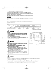
...) 131 (Max.) 230 (Max.) (C) Control Line Length (ft) Fuse or Circuit (#14) Breaker Capacity 65 (Max.) 20A # ... Fig. 23 Grounding line CAUTION q Be sure to connect the power supply line to locality. q Do not run wiring for units using inverter circuits, in the wiring diagram. For field wiring requirements, please refer to your local electrical codes. Otherwise, electrical shock may affect the operation. 10 Refer to your...
...) 131 (Max.) 230 (Max.) (C) Control Line Length (ft) Fuse or Circuit (#14) Breaker Capacity 65 (Max.) 20A # ... Fig. 23 Grounding line CAUTION q Be sure to connect the power supply line to locality. q Do not run wiring for units using inverter circuits, in the wiring diagram. For field wiring requirements, please refer to your local electrical codes. Otherwise, electrical shock may affect the operation. 10 Refer to your...

Installation Instructions
Page 11
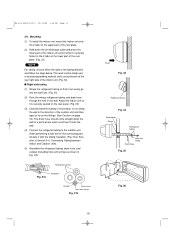
Wiring Instructions for installing the air intake grille. Rear panel Wiring Wall Plastic cover 10" (25 cm) Fig. 24 Cover Fig. 25 Terminal plate Fig. 27 Fig. 26a Earth plate Inter-unit wiring Top of the indoor unit and pull it toward the front for connection. (Fig. 26a, 26b) (5) Connect the inter-unit wiring to the corresponding terminals on page 8 for Inter-unit Connections (1) Insert the inter-unit wiring (according...
Wiring Instructions for installing the air intake grille. Rear panel Wiring Wall Plastic cover 10" (25 cm) Fig. 24 Cover Fig. 25 Terminal plate Fig. 27 Fig. 26a Earth plate Inter-unit wiring Top of the indoor unit and pull it toward the front for connection. (Fig. 26a, 26b) (5) Connect the inter-unit wiring to the corresponding terminals on page 8 for Inter-unit Connections (1) Insert the inter-unit wiring (according...
Installation Instructions
Page 13
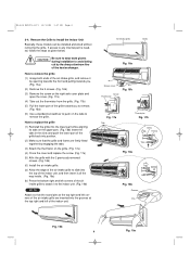
..., refer to Section 5-4. Mounting (1) To install the indoor unit, mount the indoor unit onto the 2 tabs on the upper part of the rear plate. (2) Hold down the wall to a point where water runoff won't stain the wall. (4) Connect the refrigerant tubing to the outdoor unit. (After performing a leak test on the lower part of the indoor unit until it is securely seated on the rear panel. (Fig. 36) (3) Carefully...
..., refer to Section 5-4. Mounting (1) To install the indoor unit, mount the indoor unit onto the 2 tabs on the upper part of the rear plate. (2) Hold down the wall to a point where water runoff won't stain the wall. (4) Connect the refrigerant tubing to the outdoor unit. (After performing a leak test on the lower part of the indoor unit until it is securely seated on the rear panel. (Fig. 36) (3) Carefully...

Installation Instructions
Page 14
... and wiring led inside from outdoors. (5) After completing a leak test, bundle the tubing together with armoring tape and store it inside the tubing storage area at the back of the indoor unit and hold it with water first.) (3) Install the indoor unit on the left side. (If you cannot pull it is pushed into the insulation. Switching drain hose and drain cap (a) Locate the drain hose and the drain...
... and wiring led inside from outdoors. (5) After completing a leak test, bundle the tubing together with armoring tape and store it inside the tubing storage area at the back of the indoor unit and hold it with water first.) (3) Install the indoor unit on the left side. (If you cannot pull it is pushed into the insulation. Switching drain hose and drain cap (a) Locate the drain hose and the drain...

Installation Instructions
Page 15
... lower part of the hose. Fig. 44 15 Risk of Electric Shock Push Fig. 42 Slant Indoor unit Drain hose Fig. 43 Condensation Insulation material (Locally purchased) must be slanted downward to the outside unit are completed. Then lift the indoor unit and unmount. (Fig. 42) 3-10. WARNING Do not supply power to the unit or operate it until all tubing and wiring to the outdoors...
... lower part of the hose. Fig. 44 15 Risk of Electric Shock Push Fig. 42 Slant Indoor unit Drain hose Fig. 43 Condensation Insulation material (Locally purchased) must be slanted downward to the outside unit are completed. Then lift the indoor unit and unmount. (Fig. 42) 3-10. WARNING Do not supply power to the unit or operate it until all tubing and wiring to the outdoors...

Installation Instructions
Page 16
.... (1) Remove access panel "C". (Fig. 46) (2) Connect the inter-unit and power supply line according to the drawing on the panel side. (3) Be sure to size each wire allowing approx. 4" (10 cm) longer than the required length for the Outdoor Unit Regulations on panel side. (5) Be sure to ground the unit according to Section 2. How to Install the Outdoor Unit First refer to your local electrical codes...
.... (1) Remove access panel "C". (Fig. 46) (2) Connect the inter-unit and power supply line according to the drawing on the panel side. (3) Be sure to size each wire allowing approx. 4" (10 cm) longer than the required length for the Outdoor Unit Regulations on panel side. (5) Be sure to ground the unit according to Section 2. How to Install the Outdoor Unit First refer to your local electrical codes...
Installation Instructions
Page 17
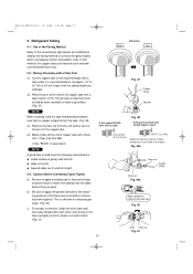
... they are flared at the end of the conventional split system air conditioners employ the flaring method to the matching surfaces of uniform length. 5-3. b) Be sure to apply refrigerant lubricant to connect refrigerant tubes which run between indoor and outdoor units. Fig. 49a Flare nut Copper tubing Flare tool Fig... apply a sealing cap or water-proof tape to obtain a smooth match. (Fig. 51) Before Deburring After Fig. 47 Copper tubing Reamer If the special R410A flare tool is used: Fig. 48 If the previous flare tool (clutch-type) is effective for reducing gas leaks. (Fig. 50) c) ...
... they are flared at the end of the conventional split system air conditioners employ the flaring method to the matching surfaces of uniform length. 5-3. b) Be sure to apply refrigerant lubricant to connect refrigerant tubes which run between indoor and outdoor units. Fig. 49a Flare nut Copper tubing Flare tool Fig... apply a sealing cap or water-proof tape to obtain a smooth match. (Fig. 51) Before Deburring After Fig. 47 Copper tubing Reamer If the special R410A flare tool is used: Fig. 48 If the previous flare tool (clutch-type) is effective for reducing gas leaks. (Fig. 50) c) ...
Installation Instructions
Page 19
... the one for other refrigerants from the service valve on the assumption that the ideal (or target) vacuum condition is more 15 min. If it is calculated based on both narrow and wide tubes) between the indoor and outdoor units have undesirable effects as recharging, the specified charging hose, manifold and vacuum pump adapter (with reverse flow prevention) for air purging.
... the one for other refrigerants from the service valve on the assumption that the ideal (or target) vacuum condition is more 15 min. If it is calculated based on both narrow and wide tubes) between the indoor and outdoor units have undesirable effects as recharging, the specified charging hose, manifold and vacuum pump adapter (with reverse flow prevention) for air purging.
Installation Instructions
Page 20
... to fully open the valve. (9) Turn the narrow tube service valve stem counterclockwise to fully open the valve. (10) Loosen the vacuum hose connected to the wide tube service port slightly to leak. Then stop the air conditioner. (15) Wipe off the soap with a clean cloth. (8) With the hex wrench, turn the valve. (7) Leak test all joints at the tubing (both indoor and outdoors) with...
... to fully open the valve. (9) Turn the narrow tube service valve stem counterclockwise to fully open the valve. (10) Loosen the vacuum hose connected to the wide tube service port slightly to leak. Then stop the air conditioner. (15) Wipe off the soap with a clean cloth. (8) With the hex wrench, turn the valve. (7) Leak test all joints at the tubing (both indoor and outdoors) with...
Installation Instructions
Page 21
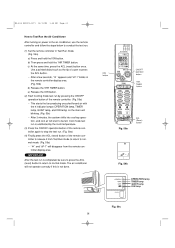
... ACL (reset) button to return to release it from the remote controller display area. b) Then press and hold the ION button. Cool mode test run is unaffected by pressing the ON/OFF operation button of the remote controller. (Fig. 59a) • This starts the fan producing uncooled forced air with the 4 indicator lamps (OPERATION lamp, TIMER lamp, QUIET lamp, and ION lamp) on power to the air conditioner, use the remote controller and...
... ACL (reset) button to return to release it from the remote controller display area. b) Then press and hold the ION button. Cool mode test run is unaffected by pressing the ON/OFF operation button of the remote controller. (Fig. 59a) • This starts the fan producing uncooled forced air with the 4 indicator lamps (OPERATION lamp, TIMER lamp, QUIET lamp, and ION lamp) on power to the air conditioner, use the remote controller and...
Installation Instructions
Page 22
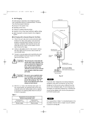
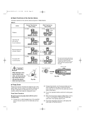
... all gauges and hoses, and replace the valve caps as they were before turning the valve. Be sure to be sure to access the refrigerant system. ing the service valve Open stem, use a hose connector which has a push-pin inside. (Fig. 60a) Service valve PUSH Fig. 60a s Pump Down Pump down is used when the unit is fully open.) (3) Press the operation button and start cooling operation. (4) When the low...
... all gauges and hoses, and replace the valve caps as they were before turning the valve. Be sure to be sure to access the refrigerant system. ing the service valve Open stem, use a hose connector which has a push-pin inside. (Fig. 60a) Service valve PUSH Fig. 60a s Pump Down Pump down is used when the unit is fully open.) (3) Press the operation button and start cooling operation. (4) When the low...
Installation Instructions
Page 23
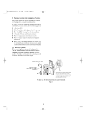
... is covered q More than 26' (8 m) away from the air conditioner q In the path of the remote control unit, you can be subject to make a beeping sound to the mount by passing a string through the remote control unit and attachment hole. 05-424 KS0971-1271 12/13/05 1:28 PM Page 23 7. Mounting on a Wall Before mounting the remote control unit, press the ON/OFF operation button at the mounting location to electrical...
... is covered q More than 26' (8 m) away from the air conditioner q In the path of the remote control unit, you can be subject to make a beeping sound to the mount by passing a string through the remote control unit and attachment hole. 05-424 KS0971-1271 12/13/05 1:28 PM Page 23 7. Mounting on a Wall Before mounting the remote control unit, press the ON/OFF operation button at the mounting location to electrical...
Installation Instructions
Page 24
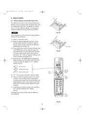
... change the display to "oP-7" (address setting). (Fig. 64) Test run ) appears, blinking, in order to cancel the blinking "oP-7" display. (Fig. 64) Changing of the air conditioner. (1) Switch on the power source. (2) Break the address-setting tab marked "A" on the second remote controller to B (Fig. 63). (3) Press and hold the remote controller ION button and 1 HR TIMER button. When this button 2 times to change the address (Fig. 62). TIMER button ACL Ĉ (Reset) button...
... change the display to "oP-7" (address setting). (Fig. 64) Test run ) appears, blinking, in order to cancel the blinking "oP-7" display. (Fig. 64) Changing of the air conditioner. (1) Switch on the power source. (2) Break the address-setting tab marked "A" on the second remote controller to B (Fig. 63). (3) Press and hold the remote controller ION button and 1 HR TIMER button. When this button 2 times to change the address (Fig. 62). TIMER button ACL Ĉ (Reset) button...


