
Service Manual
Page 42
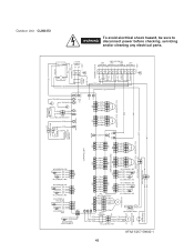
... 1234 1234 COIL/OUTDOOR 11 22 WU WV WW FM 1234567 1234 1234 A-TH BW THERMISTOR YEL YEL YEL YEL BN THERMISTOR 1234 1234 B-TH CONTROLLER WHT WHT 11 (1P)CONNECTOR 11 (1P) WHT CONNECTOR REACTANCE WHT WHT (2P)CONNECTOR WHT WHT WHT WHT WHT WHT 21 21 CRANKCASE HEATER W W ... COMPRESSOR MOTOR FM FAN MOTOR HIGH PRESSURE SWITCH BLK BLK OVERLOAD RELAY(OLR) RED BLU BRN WHT ORG 12345678 123456 12345678 123456 CN03 CN02 EXPANSION BOARD C-TH 1234 1234 1234 1234 CN01 MV2 12345 12345 W SICOM2 SI-C W 12345 12345 12345 12345 MV1 MV0 MAGNETIC COIL MAGNETIC COIL ORG RED YEL ...
... 1234 1234 COIL/OUTDOOR 11 22 WU WV WW FM 1234567 1234 1234 A-TH BW THERMISTOR YEL YEL YEL YEL BN THERMISTOR 1234 1234 B-TH CONTROLLER WHT WHT 11 (1P)CONNECTOR 11 (1P) WHT CONNECTOR REACTANCE WHT WHT (2P)CONNECTOR WHT WHT WHT WHT WHT WHT 21 21 CRANKCASE HEATER W W ... COMPRESSOR MOTOR FM FAN MOTOR HIGH PRESSURE SWITCH BLK BLK OVERLOAD RELAY(OLR) RED BLU BRN WHT ORG 12345678 123456 12345678 123456 CN03 CN02 EXPANSION BOARD C-TH 1234 1234 1234 1234 CN01 MV2 12345 12345 W SICOM2 SI-C W 12345 12345 12345 12345 MV1 MV0 MAGNETIC COIL MAGNETIC COIL ORG RED YEL ...
Service Manual
Page 43
...CLM2472 8FA2-5257-59600-1 43 COMPRESSOR THERMISTOR BLK BLK COMP COIL THERMISTOR YEL YEL BLK BLK OUTDOOR THERMISTOR AW THERMISTOR YEL YEL YEL YEL AN THERMISTOR 1234 1234 COIL/OUTDOOR 11 22 WU WV WW FM 1234567 1234 1234 A-TH BW THERMISTOR YEL YEL YEL YEL BN THERMISTOR 1234 1234 B-TH CONTROLLER... CM COMPRESSOR MOTOR FM FAN MOTOR HIGH PRESSURE SWITCH BLK BLK OVERLOAD RELAY(OLR) ORG DW THERMISTOR 12345678 123456 12345678 123456 CN03 CN02 EXPANSION BOARD D-TH C-TH MV3 1234 1234 12345 1234 1234 12345 1234 1234 CN01 MV2 12345 12345 W SICOM2 SI-D SI-C W W 12345 12345...
...CLM2472 8FA2-5257-59600-1 43 COMPRESSOR THERMISTOR BLK BLK COMP COIL THERMISTOR YEL YEL BLK BLK OUTDOOR THERMISTOR AW THERMISTOR YEL YEL YEL YEL AN THERMISTOR 1234 1234 COIL/OUTDOOR 11 22 WU WV WW FM 1234567 1234 1234 A-TH BW THERMISTOR YEL YEL YEL YEL BN THERMISTOR 1234 1234 B-TH CONTROLLER... CM COMPRESSOR MOTOR FM FAN MOTOR HIGH PRESSURE SWITCH BLK BLK OVERLOAD RELAY(OLR) ORG DW THERMISTOR 12345678 123456 12345678 123456 CN03 CN02 EXPANSION BOARD D-TH C-TH MV3 1234 1234 12345 1234 1234 12345 1234 1234 CN01 MV2 12345 12345 W SICOM2 SI-D SI-C W W 12345 12345...

Service Manual
Page 44
...1234 1234 COIL/OUTDOOR 11 22 WU WV WW FM 1234567 1234 1234 A-TH BW THERMISTOR YEL YEL YEL YEL BN THERMISTOR 1234 1234 B-TH CONTROLLER WHT WHT 11 (1P)CONNECTOR 11 (1P) WHT CONNECTOR REACTANCE WHT WHT (2P)CONNECTOR WHT WHT WHT WHT WHT WHT 21 21 CRANKCASE ...R/V S/U C/W CM COMPRESSOR MOTOR FM FAN MOTOR HIGH PRESSURE SWITCH BLK BLK OVERLOAD RELAY(OLR) ORG DW THERMISTOR 12345678 123456 12345678 123456 CN03 CN02 EXPANSION BOARD D-TH C-TH MV3 1234 1234 12345 1234 1234 12345 1234 1234 CN01 MV2 12345 12345 W SICOM2 SI-D SI-C W W 12345 12345 12345 12345 ...
...1234 1234 COIL/OUTDOOR 11 22 WU WV WW FM 1234567 1234 1234 A-TH BW THERMISTOR YEL YEL YEL YEL BN THERMISTOR 1234 1234 B-TH CONTROLLER WHT WHT 11 (1P)CONNECTOR 11 (1P) WHT CONNECTOR REACTANCE WHT WHT (2P)CONNECTOR WHT WHT WHT WHT WHT WHT 21 21 CRANKCASE ...R/V S/U C/W CM COMPRESSOR MOTOR FM FAN MOTOR HIGH PRESSURE SWITCH BLK BLK OVERLOAD RELAY(OLR) ORG DW THERMISTOR 12345678 123456 12345678 123456 CN03 CN02 EXPANSION BOARD D-TH C-TH MV3 1234 1234 12345 1234 1234 12345 1234 1234 CN01 MV2 12345 12345 W SICOM2 SI-D SI-C W W 12345 12345 12345 12345 ...

Service Manual
Page 51
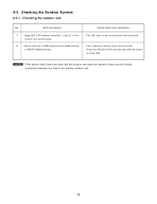
...capacitors. 51 For example, if the outdoor control circuit board fuse has blown, approximately 30 minutes will be trouble with the outdoor control circuit board. 8. High-capacity electrolytic capacitors are used inside the outdoor unit controller (inverter). If the outdoor control circuit board is normal, approximately 180 seconds will be... any electrified parts before Performing Inspection or Repair Both the indoor unit and outdoor unit include electronic control circuits. TROUBLESHOOTING 8-1. However, allow at least 30 minutes for the charge to dissipate. Precautions before the...
...capacitors. 51 For example, if the outdoor control circuit board fuse has blown, approximately 30 minutes will be trouble with the outdoor control circuit board. 8. High-capacity electrolytic capacitors are used inside the outdoor unit controller (inverter). If the outdoor control circuit board is normal, approximately 180 seconds will be... any electrified parts before Performing Inspection or Repair Both the indoor unit and outdoor unit include electronic control circuits. TROUBLESHOOTING 8-1. However, allow at least 30 minutes for the charge to dissipate. Precautions before the...

Service Manual
Page 52
...8-2. Trouble Diagnosis by Error Monitor Lamps To prevent electric shock, do not inspect or repair until WARNING the Power Lamp on the P.C.Board is a sensor failure in the outdoor unit, the 4 error monitor lamps on indoor LED 52 Display of Electrical Component Box. Error ...Fig.1 View from top 8-2-2. The Power Lamp and Error Monitor Lamps are located on the P.C.Board of Electrical Component Box. (Fig.1) Heat Exchanger Rear side P.C.Board of error message indicate on the outdoor control circuit board will indicate the nature of the trouble. : ON : OFF Error Monitor Lamp ERR0 ERR1 ...
...8-2. Trouble Diagnosis by Error Monitor Lamps To prevent electric shock, do not inspect or repair until WARNING the Power Lamp on the P.C.Board is a sensor failure in the outdoor unit, the 4 error monitor lamps on indoor LED 52 Display of Electrical Component Box. Error ...Fig.1 View from top 8-2-2. The Power Lamp and Error Monitor Lamps are located on the P.C.Board of Electrical Component Box. (Fig.1) Heat Exchanger Rear side P.C.Board of error message indicate on the outdoor control circuit board will indicate the nature of the trouble. : ON : OFF Error Monitor Lamp ERR0 ERR1 ...
Service Manual
Page 53
...-circuit the T-RUN terminal to the COM terminal of TEST/T-RUN terminals. Work procedure 1 • Apply 220 V AC between terminals L1 and L2 on the control board must illuminate. • The compressor and fan motor must turn ON. (They turn ON about (70) seconds later after the power is turned ON.) NOTE...
...-circuit the T-RUN terminal to the COM terminal of TEST/T-RUN terminals. Work procedure 1 • Apply 220 V AC between terminals L1 and L2 on the control board must illuminate. • The compressor and fan motor must turn ON. (They turn ON about (70) seconds later after the power is turned ON.) NOTE...
Service Manual
Page 54
...) Indoor fan motor Room temperature sensor Heat exchanger temperature sensor Inter-unit cable Switch circuit board Outdoor control circuit board (1) Diode module HIC Electrolytic capacitor Fuse (2) Compressor (3) Compressor protective sensor (4) Outdoor fan motor Coil thermistor (5) Electric expansion valve (6) Branch tubing temperature sensor (7) Outdoor unit 54 ...
...) Indoor fan motor Room temperature sensor Heat exchanger temperature sensor Inter-unit cable Switch circuit board Outdoor control circuit board (1) Diode module HIC Electrolytic capacitor Fuse (2) Compressor (3) Compressor protective sensor (4) Outdoor fan motor Coil thermistor (5) Electric expansion valve (6) Branch tubing temperature sensor (7) Outdoor unit 54 ...
Service Manual
Page 55
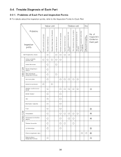
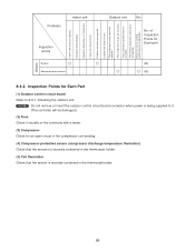
... Problems Indoor unit Inspection points Breaker Refrigerant gas pressure Outdoor unit Others No. NOTE Do not remove or insert the outdoor control circuit board connector when power is being supplied to 8-3-1. of Inspection Points for an open circuit in the compressor coil winding. (4)...is inadequate. Indoor fan dose not turn . The compressor speed does not increase. Inspection Points for Each Part (1) Outdoor control circuit board Refer to it. (The controller will be damaged.) (2) Fuse Check it visually or the continuity with a tester. (3) Compressor Check for Each part (8) ...
... Problems Indoor unit Inspection points Breaker Refrigerant gas pressure Outdoor unit Others No. NOTE Do not remove or insert the outdoor control circuit board connector when power is being supplied to 8-3-1. of Inspection Points for an open circuit in the compressor coil winding. (4)...is inadequate. Indoor fan dose not turn . The compressor speed does not increase. Inspection Points for Each Part (1) Outdoor control circuit board Refer to it. (The controller will be damaged.) (2) Fuse Check it visually or the continuity with a tester. (3) Compressor Check for Each part (8) ...
Service Manual
Page 56
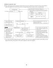
Controller check No voltage on circuit board Voltage varies Use a multi-meter to identify them. Check the coil resistance. 0 ohm Approx. 46 +/- 4...valve body and coil, corresponding to the connector colors, to measure the voltage (12 V). Replace the controller. Use the special service magnet and rotate 5 revolutions clockwise to fully close the electric expansion valve by ... the gray lead wire and the other means while welding. Check elsewhere. Sequence CLM1972 MV0 MV1 MV2 CLM2472 CLM3172 MV0 MV1 MV2 MV3 Check the illumination of the red Power Lamp. Replace the coil. *1 ...
Controller check No voltage on circuit board Voltage varies Use a multi-meter to identify them. Check the coil resistance. 0 ohm Approx. 46 +/- 4...valve body and coil, corresponding to the connector colors, to measure the voltage (12 V). Replace the controller. Use the special service magnet and rotate 5 revolutions clockwise to fully close the electric expansion valve by ... the gray lead wire and the other means while welding. Check elsewhere. Sequence CLM1972 MV0 MV1 MV2 CLM2472 CLM3172 MV0 MV1 MV2 MV3 Check the illumination of the red Power Lamp. Replace the coil. *1 ...

Service Manual
Page 92
...connected. Installation Check Sheet The strength of the refrigerant circuit has been conducted. Inter-unit cables are secure and water drains properly. An air purge of the installation location is sufficient to support the A/C weight. A leak test of the tubing connections has been performed. 7. ... PCB. Putty has been used , connect it to the terminal board. The indoor and outdoor units are securely fastened to this terminal. 8. If a HA device will be used to the tubing connections. Remote controller signals are not connected anywhere along their paths. The power cord...
...connected. Installation Check Sheet The strength of the refrigerant circuit has been conducted. Inter-unit cables are secure and water drains properly. An air purge of the installation location is sufficient to support the A/C weight. A leak test of the tubing connections has been performed. 7. ... PCB. Putty has been used , connect it to the terminal board. The indoor and outdoor units are securely fastened to this terminal. 8. If a HA device will be used to the tubing connections. Remote controller signals are not connected anywhere along their paths. The power cord...

