Service Manual
Page 2
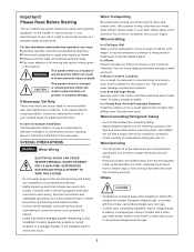
... to provide added support. Sharp edges or thin aluminum fins on the air conditioner can cause dripping and water damage to hold the unit's weight. In a Room Properly insulate any tubing run . If escaped gas comes in this document. As the installer or service person, it is strong enough to walls and floors...
... to provide added support. Sharp edges or thin aluminum fins on the air conditioner can cause dripping and water damage to hold the unit's weight. In a Room Properly insulate any tubing run . If escaped gas comes in this document. As the installer or service person, it is strong enough to walls and floors...

Service Manual
Page 3
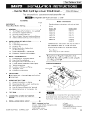
OPERATING RANGE ...5 2. PERFORMANCE DATA 5-1. REFRIGERANT R410A: SPECIAL PRECAUTIONS WHEN SERVICING UNIT 9-1. In Case Refrigerant is Leaking 60 9-7. Refrigerant Flow Diagram 19 5. Precautions before Servicing 56 9-3. Tubing Installation Procedures 57 9-5. Retro-Fitting Existing Systems 61 APPENDIX A INSTALLATION INSTRUCTIONS A-1 APPENDIX B UNIT COMBINATION TABLES A-2 3 SPECIFICATIONS 2-1. Major Component Specifications 12 2-3. Other Component Specifications 15 3. ELECTRICAL DATA 6-1. Electric Wiring...
OPERATING RANGE ...5 2. PERFORMANCE DATA 5-1. REFRIGERANT R410A: SPECIAL PRECAUTIONS WHEN SERVICING UNIT 9-1. In Case Refrigerant is Leaking 60 9-7. Refrigerant Flow Diagram 19 5. Precautions before Servicing 56 9-3. Tubing Installation Procedures 57 9-5. Retro-Fitting Existing Systems 61 APPENDIX A INSTALLATION INSTRUCTIONS A-1 APPENDIX B UNIT COMBINATION TABLES A-2 3 SPECIFICATIONS 2-1. Major Component Specifications 12 2-3. Other Component Specifications 15 3. ELECTRICAL DATA 6-1. Electric Wiring...

Service Manual
Page 54
... of indoor unit. Important: (A) Turn OFF the power before connecting or disconnecting the motor connectors. (B) When performing voltage measurement at the DC motor connectors on Installation Instructions of Fan Motor This outdoor DC fan motor contains an internal control PCB. Therefore, first replace the outdoor unit controller, then (if necessary) replace...
... of indoor unit. Important: (A) Turn OFF the power before connecting or disconnecting the motor connectors. (B) When performing voltage measurement at the DC motor connectors on Installation Instructions of Fan Motor This outdoor DC fan motor contains an internal control PCB. Therefore, first replace the outdoor unit controller, then (if necessary) replace...

Service Manual
Page 56
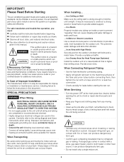
... R407C. Never use a refrigerant other than those using the flare spacer. Therefore, be released when R410A refrigerant is permitted. Caution in thickness, since air conditioners with caps or tape prior to higher pressure than R410A. No addition of flare D D Spacer A A Flare tool for R410A. If a leak... conventional flare tool. No use of refrigerant other than 0.0315" (0.8 mm) in case of the tubing with R410A are subject to installation. If refrigerant R410A is exposed to fire Through welding, etc., toxic gas may be sure to fire. Note that sizes of compressor ...
... R407C. Never use a refrigerant other than those using the flare spacer. Therefore, be released when R410A refrigerant is permitted. Caution in thickness, since air conditioners with caps or tape prior to higher pressure than R410A. No addition of flare D D Spacer A A Flare tool for R410A. If a leak... conventional flare tool. No use of refrigerant other than 0.0315" (0.8 mm) in case of the tubing with R410A are subject to installation. If refrigerant R410A is exposed to fire Through welding, etc., toxic gas may be sure to fire. Note that sizes of compressor ...

Service Manual
Page 57
...vacuum pump adapter (*3), those for R22-type units can be used for R410A and never alternately with anti-reverse flow (*1) (Solenoid valve-installed type, which can be used exclusively for R410A-type. For the above tools specifically for R410A must be used if the following is ...when the power is off, is the HAB oil generally used for R22 and R407C. Tubing Installation Procedures When the tubes are connected, always apply HAB oil on tubing installation procedures, refer to the installation manuals attached to improve the sealing of the unit. R410A : 5/16" R22, R407C : ...
...vacuum pump adapter (*3), those for R22-type units can be used for R410A and never alternately with anti-reverse flow (*1) (Solenoid valve-installed type, which can be used exclusively for R410A-type. For the above tools specifically for R410A must be used if the following is ...when the power is off, is the HAB oil generally used for R22 and R407C. Tubing Installation Procedures When the tubes are connected, always apply HAB oil on tubing installation procedures, refer to the installation manuals attached to improve the sealing of the unit. R410A : 5/16" R22, R407C : ...

Service Manual
Page 58
... sure to make the switch to a replacement compressor as quickly as possible. and ultimate vacuum pressure rate of air due to the atmosphere, but recovered using a vacuum pump with exhaust air volume more than 0.883 cu.ft./min. 9-5. When using the refrigerant recovery unit for R410A. In Case...other than 15 minutes 58 Tools Specifically for the pressurized gas, and never use oxygen or any flammable gas. (4) Evacuation Use a solenoid valve-installed vacuum pump so that even if power is cut off in the tubing, thus carry out the evacuation thoroughly. Do not reuse the recovered ...
... sure to make the switch to a replacement compressor as quickly as possible. and ultimate vacuum pressure rate of air due to the atmosphere, but recovered using a vacuum pump with exhaust air volume more than 0.883 cu.ft./min. 9-5. When using the refrigerant recovery unit for R410A. In Case...other than 15 minutes 58 Tools Specifically for the pressurized gas, and never use oxygen or any flammable gas. (4) Evacuation Use a solenoid valve-installed vacuum pump so that even if power is cut off in the tubing, thus carry out the evacuation thoroughly. Do not reuse the recovered ...

Service Manual
Page 60
...Detecting Leaks Use the detector for R410A, instead. recover residual refrigerant using flux and wax for sealing OK (5) Evacuation Use a solenoid valve-installed vacuum pump so that no residual refrigerant exists in the unit before starting welding. Also do not use a refrigerant other than 15 minutes... (6) Recharging Recharge unit in the middle of evacuation of air due to locate points of the unit. and ultimate vacuum pressure rate of 50 micron Hg. (5) Evacuation OK (6) Recharge Standard time...
...Detecting Leaks Use the detector for R410A, instead. recover residual refrigerant using flux and wax for sealing OK (5) Evacuation Use a solenoid valve-installed vacuum pump so that no residual refrigerant exists in the unit before starting welding. Also do not use a refrigerant other than 15 minutes... (6) Recharging Recharge unit in the middle of evacuation of air due to locate points of the unit. and ultimate vacuum pressure rate of 50 micron Hg. (5) Evacuation OK (6) Recharge Standard time...

Service Manual
Page 61
... then should you recharge the refrigerant. 9-8. Retro-Fitting Existing Systems 9-8-1. Follow instructions given in liquid state only. This will cause the air conditioner to operate improperly and may result in this service manual or the installation manual that used . 61 Instead, completely new tubing must be used refrigerant R22 with the indoor unit.
... then should you recharge the refrigerant. 9-8. Retro-Fitting Existing Systems 9-8-1. Follow instructions given in liquid state only. This will cause the air conditioner to operate improperly and may result in this service manual or the installation manual that used . 61 Instead, completely new tubing must be used refrigerant R22 with the indoor unit.

Service Manual
Page 62
APPENDIX A INSTALLATION INSTRUCTIONS CM1972 CM2472 CM3172 (II-852-6-4190-214-00-3) A-1
APPENDIX A INSTALLATION INSTRUCTIONS CM1972 CM2472 CM3172 (II-852-6-4190-214-00-3) A-1
Service Manual
Page 63
... 2-5. Outdoor Unit 2-4 Baffle Plate for Installation 2. Caution before Connecting Tubes Tightly 3-5. Finishing the Installation Indoor Unit KMS0772 KMS0972 KMS1272 KMS1872 KMS2472 Outdoor Unit CM1972 CM2472 CM3172 CLM1972 CLM2472 CLM3172 Combine indoor ... are installing. 8. Inverter Multi Split System Air Conditioner - Tools Required for 3-room or 4-room outdoor unit as listed below. 1. Insulation of Outdoor Unit Installation 3. AIR PURGING 18 I Pump Down 5. INSTALLATION CHECK SHEET 26 85264190214003 © SANYO 2007 SANYO Commercial Solutions...
... 2-5. Outdoor Unit 2-4 Baffle Plate for Installation 2. Caution before Connecting Tubes Tightly 3-5. Finishing the Installation Indoor Unit KMS0772 KMS0972 KMS1272 KMS1872 KMS2472 Outdoor Unit CM1972 CM2472 CM3172 CLM1972 CLM2472 CLM3172 Combine indoor ... are installing. 8. Inverter Multi Split System Air Conditioner - Tools Required for 3-room or 4-room outdoor unit as listed below. 1. Insulation of Outdoor Unit Installation 3. AIR PURGING 18 I Pump Down 5. INSTALLATION CHECK SHEET 26 85264190214003 © SANYO 2007 SANYO Commercial Solutions...
Service Manual
Page 64
... unit down with fire or heat, can produce dangerously toxic gas. • Do not install only a single indoor unit. 2 Provide snow vents. Escaped refrigerant gas, on the air conditioner can cause accidental injury or death. • Ground the unit following local electrical codes.... • Connect all warning and caution notices given in this document. Please Read Before Starting This air conditioning system meets strict safety and ...
... unit down with fire or heat, can produce dangerously toxic gas. • Do not install only a single indoor unit. 2 Provide snow vents. Escaped refrigerant gas, on the air conditioner can cause accidental injury or death. • Ground the unit following local electrical codes.... • Connect all warning and caution notices given in this document. Please Read Before Starting This air conditioning system meets strict safety and ...
Service Manual
Page 65
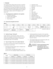
... tubing as required to dampen vibration between units. 2. Standard screwdriver 2. Core bits 9. Type of wiring. Use insulated copper wire for Installation (not supplied) 1. Table 2 Model KMS0772 KMS0972 KMS1272 KMS1872 KMS2472 Narrow Tube Outer Dia. Sabre saw or key hole saw 7. Reamer... This booklet briefly outlines where and how to purchase these materials separately from a local source, you wish to install the air conditioning system. Manifold valve Figure Q'ty Parts 4 Reducer (1/2" 3/8") 1972 1 Figure Q'ty 2472 1 3172 2 Packed in Table 2.
... tubing as required to dampen vibration between units. 2. Standard screwdriver 2. Core bits 9. Type of wiring. Use insulated copper wire for Installation (not supplied) 1. Table 2 Model KMS0772 KMS0972 KMS1272 KMS1872 KMS2472 Narrow Tube Outer Dia. Sabre saw or key hole saw 7. Reamer... This booklet briefly outlines where and how to purchase these materials separately from a local source, you wish to install the air conditioning system. Manifold valve Figure Q'ty Parts 4 Reducer (1/2" 3/8") 1972 1 Figure Q'ty 2472 1 3172 2 Packed in Table 2.

Service Manual
Page 66
... of the unit. CAUTION For stable operation of the Indoor unit Wall air conditioner, do not place obstacles, enclosures and grilles in front of or surrounding the air conditioner in rooms that will hold the weight of the unit. Refrigeration (armored) tape 2. Installation Site Selection 2-1. AVOID: Drain hose Outside drainage Fig. 1 G direct sunlight. Additional Materials...
... of the unit. CAUTION For stable operation of the Indoor unit Wall air conditioner, do not place obstacles, enclosures and grilles in front of or surrounding the air conditioner in rooms that will hold the weight of the unit. Refrigeration (armored) tape 2. Installation Site Selection 2-1. AVOID: Drain hose Outside drainage Fig. 1 G direct sunlight. Additional Materials...
Service Manual
Page 67
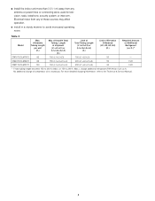
...For more than 3.3' (1 m) away from any antenna or power lines or connecting wires used for television, radio, telephone, security system, or intercom. G Install the indoor unit more detailed charging information, refer to 230 ft. (Max.), charge additional refrigerant (R410A) by 0.22 oz./ft. Table 3 Model Max. ...No additional charge of Additional Refrigerant (oz./ft.)* CM1972/CLM1972 82 150 (L1+L2+L3) 150 (L1+L2+L3) 50 - CM2472/CLM2472 82 150 (L1+L2+L3+L4) 200 (L1+L2+L3+L4...
...For more than 3.3' (1 m) away from any antenna or power lines or connecting wires used for television, radio, telephone, security system, or intercom. G Install the indoor unit more detailed charging information, refer to 230 ft. (Max.), charge additional refrigerant (R410A) by 0.22 oz./ft. Table 3 Model Max. ...No additional charge of Additional Refrigerant (oz./ft.)* CM1972/CLM1972 82 150 (L1+L2+L3) 150 (L1+L2+L3) 50 - CM2472/CLM2472 82 150 (L1+L2+L3+L4) 200 (L1+L2+L3+L4...

Service Manual
Page 72
... Min. 6" (15 cm) Air intake Drain holes G Install cushion rubber under unit's feet to reduce vibration and noise. (Fig. 5e) G use baffle plates for the Outdoor Unit (CLM models only) Concrete or equal NOTE It is operated at low speed when the air conditioner is recommended to use lug bolts... or equal to bolt down unit, reducing vibration and noise. The baffle plates are not normally required for air intake/ exhaust and possible maintenance. (Fig. 5b) G provide a solid...
... Min. 6" (15 cm) Air intake Drain holes G Install cushion rubber under unit's feet to reduce vibration and noise. (Fig. 5e) G use baffle plates for the Outdoor Unit (CLM models only) Concrete or equal NOTE It is operated at low speed when the air conditioner is recommended to use lug bolts... or equal to bolt down unit, reducing vibration and noise. The baffle plates are not normally required for air intake/ exhaust and possible maintenance. (Fig. 5b) G provide a solid...

Service Manual
Page 74
...prescribed position. 3. Panel top Panel front Panel side R 2. Air Discharge Baffle 1. Use washers and spring washers to tightly fasten the windbaffle to prevent the unit from the unit and drill 4 holes of the bolts is installed on the unit using field supply bolts and nuts. 4. Particular... painted surfaces. 2. Remove the panel side R from the unit. 2. Install the windbaffle on the unit, the unit has higher wind resistance. Recommended bolts to install the baffle plate. 3. G When the windbaffle is between 13/32 - 19/32 inch (10 - 15 mm). 4. Use 2 preholes on the unit...
...prescribed position. 3. Panel top Panel front Panel side R 2. Air Discharge Baffle 1. Use washers and spring washers to tightly fasten the windbaffle to prevent the unit from the unit and drill 4 holes of the bolts is installed on the unit using field supply bolts and nuts. 4. Particular... painted surfaces. 2. Remove the panel side R from the unit. 2. Install the windbaffle on the unit, the unit has higher wind resistance. Recommended bolts to install the baffle plate. 3. G When the windbaffle is between 13/32 - 19/32 inch (10 - 15 mm). 4. Use 2 preholes on the unit...

Service Manual
Page 76
...D C Over 1'8"(50cm) B A Base (not provided) (concrete or similar material) Fasten with the outdoor unit. (Use caution. Install in a location where the dimensions indicated by in the figure below are required in order to maintain performance. In principle, the top... and malfunction.) The dimensions indicated by are unobstructed. Diagram of the unit are ensured, and where 2 or more faces of Outdoor Unit Installation Never install only a single indoor unit. Connecting any other model may result in the combination table that are spaces that was provided with anchor bolts ...
...D C Over 1'8"(50cm) B A Base (not provided) (concrete or similar material) Fasten with the outdoor unit. (Use caution. Install in a location where the dimensions indicated by in the figure below are required in order to maintain performance. In principle, the top... and malfunction.) The dimensions indicated by are unobstructed. Diagram of the unit are ensured, and where 2 or more faces of Outdoor Unit Installation Never install only a single indoor unit. Connecting any other model may result in the combination table that are spaces that was provided with anchor bolts ...

Service Manual
Page 77
... which run between indoor and outdoor units. AWG (American Wire Gauge) G Be sure to apply the provided labels to both ends of the conventional split system air conditioners employ the flaring method to bind refrigerant tubing and inter-unit cables together with a tube cutter. This process is recommended to cut approx. 12" to... you estimate. (2) Remove burrs at each end and connected with vinyl tape in order to prevent miswiring. In this method, the copper tubes are embedded. Installation Process 3-1. G Securely seal the end of the copper tube with a tube reamer or file.
... which run between indoor and outdoor units. AWG (American Wire Gauge) G Be sure to apply the provided labels to both ends of the conventional split system air conditioners employ the flaring method to bind refrigerant tubing and inter-unit cables together with a tube cutter. This process is recommended to cut approx. 12" to... you estimate. (2) Remove burrs at each end and connected with vinyl tape in order to prevent miswiring. In this method, the copper tubes are embedded. Installation Process 3-1. G Securely seal the end of the copper tube with a tube reamer or file.

Service Manual
Page 79
Finishing the Installation After finishing insulating and taping over the tubing, use sealing putty... a minimum 5/16" (8 mm). (Fig. 17) 3-7. The drain hose may also be sure the condensation drain hose splits away from entering. (Fig. 19) Torque wrench Indoor unit Spanner Outdoor unit Fig. 15 Min. 5/16" (8 mm) Insulation Fig. 16 Insulation Thickness:... min. 5/16" (8 mm) Fig. 17 Clamp Insulated tubes Fig. 18 Apply putty here Tubing Fig. 19 17 Also, be included and taped together as this will decrease the heat insulation effect. For more details, refer to "...
Finishing the Installation After finishing insulating and taping over the tubing, use sealing putty... a minimum 5/16" (8 mm). (Fig. 17) 3-7. The drain hose may also be sure the condensation drain hose splits away from entering. (Fig. 19) Torque wrench Indoor unit Spanner Outdoor unit Fig. 15 Min. 5/16" (8 mm) Insulation Fig. 16 Insulation Thickness:... min. 5/16" (8 mm) Fig. 17 Clamp Insulated tubes Fig. 18 Apply putty here Tubing Fig. 19 17 Also, be included and taped together as this will decrease the heat insulation effect. For more details, refer to "...

Service Manual
Page 83
... unit as a result of local codes see the National Electric Code: ANSI/NFPA70. Wiring Instructions 5-1. Carefully observe these regulations when carrying out the installation. Control Line Length (ft.) (A) (B) (C) (#12) (#14) Fuse or Circuit Capasity 85 (Max.) 82 (Max.) 20 A 85 (Max....) 82 (Max.) 20 A 85 (Max.) 100 (Max.) 20 A # ... Table 6 Model AWG CM1972 / CLM1972 CM2472 / CLM2472 CM3172 / CLM3172 Max. For field wiring requirements, please refer to your local electrical codes. Power Line Length (ft.) Max. The ...
... unit as a result of local codes see the National Electric Code: ANSI/NFPA70. Wiring Instructions 5-1. Carefully observe these regulations when carrying out the installation. Control Line Length (ft.) (A) (B) (C) (#12) (#14) Fuse or Circuit Capasity 85 (Max.) 82 (Max.) 20 A 85 (Max....) 82 (Max.) 20 A 85 (Max.) 100 (Max.) 20 A # ... Table 6 Model AWG CM1972 / CLM1972 CM2472 / CLM2472 CM3172 / CLM3172 Max. For field wiring requirements, please refer to your local electrical codes. Power Line Length (ft.) Max. The ...