
Service Manual
Page 1
... restored to its original condition and only parts identical to change without notice. TOUCH CONTROL PANEL ASSEMBLY CHAPTER 1. WARNING TO SERVICE PERSONNEL: Microwave ovens contain circuitry capable of user-safety the oven should be used for after sales service only. PRECAUTIONS FOR USING LEADFREE SOLDER CHAPTER 11. COMPONENT REPLACEMENT AND ADJUSTMENT PROCEDURE CHAPTER 4. GENERAL INFORMATION CHAPTER 6. TEST PROCEDURES CHAPTER 9. R-351NW SERVICE MANUAL Palomitas de Maiz Minuto Extra Nivel de...
... restored to its original condition and only parts identical to change without notice. TOUCH CONTROL PANEL ASSEMBLY CHAPTER 1. WARNING TO SERVICE PERSONNEL: Microwave ovens contain circuitry capable of user-safety the oven should be used for after sales service only. PRECAUTIONS FOR USING LEADFREE SOLDER CHAPTER 11. COMPONENT REPLACEMENT AND ADJUSTMENT PROCEDURE CHAPTER 4. GENERAL INFORMATION CHAPTER 6. TEST PROCEDURES CHAPTER 9. R-351NW SERVICE MANUAL Palomitas de Maiz Minuto Extra Nivel de...
Service Manual
Page 2
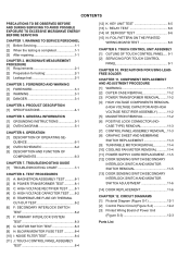
... G: MOTOR SWITCH TEST 8-3 [9] H: BLOWN MONITOR FUSE TEST 8-4 [10] I: NOISE FILTER TEST 8-4 [11] J: TOUCH CONTROL PANEL ASSEMBLY TEST 8-4 [12] K: KEY UNIT TEST 8-5 [13] L: RELAY TEST 8-6 [14] M: DEFROST TEST 8-6 [15] N: FOIL PATTERN ON THE PRINTED WIRING BOARD TEST 8-6 CHAPTER 9. FOREWORD AND WARNING [1] FOREWORD 3-1 [2] WARNING 3-1 [3] DANGER 3-1 CHAPTER 4. QUENCE 6-1 [2] OVEN SCHEMATIC 6-2 [3] DESCRIPTION AND FUNCTION OF COMPONENTS 6-3 CHAPTER 7. GENERAL INFORMATION [1] GROUNDING INSTRUCTIONS 5-1 [2] OVEN DIAGRAM 5-1 CHAPTER 6. OPERATION [1] DESCRIPTION OF OPERATING SE...
... G: MOTOR SWITCH TEST 8-3 [9] H: BLOWN MONITOR FUSE TEST 8-4 [10] I: NOISE FILTER TEST 8-4 [11] J: TOUCH CONTROL PANEL ASSEMBLY TEST 8-4 [12] K: KEY UNIT TEST 8-5 [13] L: RELAY TEST 8-6 [14] M: DEFROST TEST 8-6 [15] N: FOIL PATTERN ON THE PRINTED WIRING BOARD TEST 8-6 CHAPTER 9. FOREWORD AND WARNING [1] FOREWORD 3-1 [2] WARNING 3-1 [3] DANGER 3-1 CHAPTER 4. QUENCE 6-1 [2] OVEN SCHEMATIC 6-2 [3] DESCRIPTION AND FUNCTION OF COMPONENTS 6-3 CHAPTER 7. GENERAL INFORMATION [1] GROUNDING INSTRUCTIONS 5-1 [2] OVEN DIAGRAM 5-1 CHAPTER 6. OPERATION [1] DESCRIPTION OF OPERATING SE...
Service Manual
Page 3
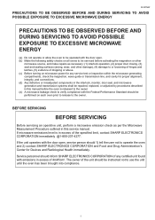
... be repaired, replaced, or adjusted by procedures described in this service manual. If microwave emissions level is released to the own. Service personnel should be performed on microwave power for any certified unit found with the door open . (b) Make the following safety checks on all ovens to be serviced before activating the magnetron or other damage), (4) damage to or loosening of hinges and latches, (5) evidence...
... be repaired, replaced, or adjusted by procedures described in this service manual. If microwave emissions level is released to the own. Service personnel should be performed on microwave power for any certified unit found with the door open . (b) Make the following safety checks on all ovens to be serviced before activating the magnetron or other damage), (4) damage to or loosening of hinges and latches, (5) evidence...
Service Manual
Page 4
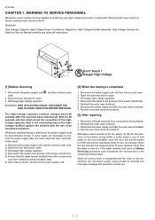
... outer case (cabinet). 6. R-351NW CHAPTER 1. Read the Service Manual carefully and follow all functions. [3] After repairing 1. Don't Touch ! Reconnect the power supply cord after the oven has been switched off. Reinstall the outer case (cabinet). 3. To test for the presence of microwave energy within a cavity, place a cup of cold water on the oven turntable, close the door and set the power to HIGH and set the microwave timer for 60 seconds...
... outer case (cabinet). 6. R-351NW CHAPTER 1. Read the Service Manual carefully and follow all functions. [3] After repairing 1. Don't Touch ! Reconnect the power supply cord after the oven has been switched off. Reinstall the outer case (cabinet). 3. To test for the presence of microwave energy within a cavity, place a cup of cold water on the oven turntable, close the door and set the power to HIGH and set the microwave timer for 60 seconds...

Service Manual
Page 5
... leakage is measured accurately. 4. While testing for leakage around the switches, indicator, and vents). Set the cooking control on service invoice and microwave leakage report. 2 - 1 Safety interlock switches: Primary interlock relay and door sensing switch shall prevent microwave radiation emission in excess of the requirement as prescribed by the performance standard for microwave ovens, 21 CFR 1030.10(c)(3)(i), must be a low form of...
... leakage is measured accurately. 4. While testing for leakage around the switches, indicator, and vents). Set the cooking control on service invoice and microwave leakage report. 2 - 1 Safety interlock switches: Primary interlock relay and door sensing switch shall prevent microwave radiation emission in excess of the requirement as prescribed by the performance standard for microwave ovens, 21 CFR 1030.10(c)(3)(i), must be a low form of...
Service Manual
Page 6
... with Operation and Service Information for the SHARP MICROWAVE OVENS, R-351NW. Service Personnel with the oven. Servicing and repair work must be given to avoid electrical shock and microwave radiation hazard. [2] WARNING Never operate the oven until the following parts while the appliance is recommended that service personnel carefully study the entire text of this manual so that they are used at voltages more than 250V. All the parts marked "*" on parts list...
... with Operation and Service Information for the SHARP MICROWAVE OVENS, R-351NW. Service Personnel with the oven. Servicing and repair work must be given to avoid electrical shock and microwave radiation hazard. [2] WARNING Never operate the oven until the following parts while the appliance is recommended that service personnel carefully study the entire text of this manual so that they are used at voltages more than 250V. All the parts marked "*" on parts list...
Service Manual
Page 8
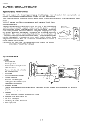
... over a longer cord. Door seals and sealing surfaces 6. Turntable motor shaft 3 2 7. Auto-Touch control panel 13. When installing this appliance be pulled on the turntable support. If the extension cord must be plugged into a wall receptacle that is recommended that a separate circuit serving only this appliance, observe all applicable codes and ordinances. Safety door latches The oven will not operate unless the 4 6 12 door is open door. 2. Removable turntable support 8 11 10 3 7 Carefully place the turntable support 9 in...
... over a longer cord. Door seals and sealing surfaces 6. Turntable motor shaft 3 2 7. Auto-Touch control panel 13. When installing this appliance be pulled on the turntable support. If the extension cord must be plugged into a wall receptacle that is recommended that a separate circuit serving only this appliance, observe all applicable codes and ordinances. Safety door latches The oven will not operate unless the 4 6 12 door is open door. 2. Removable turntable support 8 11 10 3 7 Carefully place the turntable support 9 in...

Service Manual
Page 10
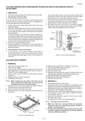
... relay (RY2), causing the monitor fuse to the turntable motor, the cooling fan motor, and the high voltage components are turned off, and the generation of component functions during a cook cycle, monitor switch, door sensing switch, secondary interlock switch, relay (RY1) and primary interlock relay are opened during oven operation. 1. POWER OUTPUT REDUCTION If the oven is stopped. To set any program or set for heating of the relays are closed...
... relay (RY2), causing the monitor fuse to the turntable motor, the cooling fan motor, and the high voltage components are turned off, and the generation of component functions during a cook cycle, monitor switch, door sensing switch, secondary interlock switch, relay (RY1) and primary interlock relay are opened during oven operation. 1. POWER OUTPUT REDUCTION If the oven is stopped. To set any program or set for heating of the relays are closed...

Service Manual
Page 12
... the door. The latch heads are in either error in cook time or defect in the power circuit. It is cooked evenly. The temperature fuse located near the magnetron is closed . R-351NW [3] DESCRIPTION AND FUNCTION OF COMPONENTS 1. However, when abnormally high temperatures are reached within the magnetron, the temperature fuse will open . COOLING FAN MOTOR The cooling fan motor drives a blade which draws external cool air. The turntable may turn in...
... the door. The latch heads are in either error in cook time or defect in the power circuit. It is cooked evenly. The temperature fuse located near the magnetron is closed . R-351NW [3] DESCRIPTION AND FUNCTION OF COMPONENTS 1. However, when abnormally high temperatures are reached within the magnetron, the temperature fuse will open . COOLING FAN MOTOR The cooling fan motor drives a blade which draws external cool air. The turntable may turn in...
Service Manual
Page 13
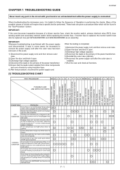
... (cabinet). 6) Reconnect the power supply cord after the outer case has been removed, in , some cases, be necessary to be performed. RECTIFIER ASSEMBLY HIGH VOLTAGE CAPACITOR TEMPERATURE FUSE or THERMAL CUT-OUT PRIMARY INTERLOCK SYSTEM SECONDARY INTERLOCK SWITCH MONITOR SWITCH MONITOR FUSE OVEN LAMP COOLING FAN MOTOR TURNTABLE MOTOR TOUCH CONTROL PANEL WRONG OPERATION LOW VOLTAGE DIRTY OVEN CAVITY KEY UNIT (MEMBRANE SWITCH) RELAY (RY1) DEFROST FOIL PATTERN ON PWB NOISE FILTER CONDITION PROBLEM Home fuse...
... (cabinet). 6) Reconnect the power supply cord after the outer case has been removed, in , some cases, be necessary to be performed. RECTIFIER ASSEMBLY HIGH VOLTAGE CAPACITOR TEMPERATURE FUSE or THERMAL CUT-OUT PRIMARY INTERLOCK SYSTEM SECONDARY INTERLOCK SWITCH MONITOR SWITCH MONITOR FUSE OVEN LAMP COOLING FAN MOTOR TURNTABLE MOTOR TOUCH CONTROL PANEL WRONG OPERATION LOW VOLTAGE DIRTY OVEN CAVITY KEY UNIT (MEMBRANE SWITCH) RELAY (RY1) DEFROST FOIL PATTERN ON PWB NOISE FILTER CONDITION PROBLEM Home fuse...
Service Manual
Page 14
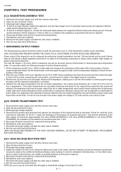
... coil should be used if above tests do not indicate a faulty magnetron and there is installed. 8. If a short is indicated in both directions, the rectifier is installed. 9. Run the oven and check all leads removed from components during testing. 6. Power output of a watch , second hand of the magnetron can be replaced. 6. Disconnect the power supply cord, and then remove outer case...
... coil should be used if above tests do not indicate a faulty magnetron and there is installed. 8. If a short is indicated in both directions, the rectifier is installed. 9. Run the oven and check all leads removed from components during testing. 6. Power output of a watch , second hand of the magnetron can be replaced. 6. Disconnect the power supply cord, and then remove outer case...
Service Manual
Page 15
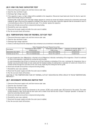
... open temperature fuse (Magnetron) or thermal cut -out and check inside of oven cavity and for a short time and should indicate an open circuit with the door open , no high voltage will indicate continuity for improper setting of cooking time or operation of the magnetron. Reinstall the outer case (cabinet). 7. This is indicated, replace the secondary interlock switch. 5. Discharge high voltage capacitor. 4. Disconnect the power supply cord, and then remove outer case. 2. Open...
... open temperature fuse (Magnetron) or thermal cut -out and check inside of oven cavity and for a short time and should indicate an open circuit with the door open , no high voltage will indicate continuity for improper setting of cooking time or operation of the magnetron. Reinstall the outer case (cabinet). 7. This is indicated, replace the secondary interlock switch. 5. Discharge high voltage capacitor. 4. Disconnect the power supply cord, and then remove outer case. 2. Open...

Service Manual
Page 17
... components during testing. 6. R-351NW [9] H: BLOWN MONITOR FUSE TEST 1. Reconnect all . Open the door and block it open . 3. Short circuit. Discharge high voltage capacitor. 4. WHITE RED [11] J: TOUCH CONTROL PANEL ASSEMBLY TEST The touch control panel consists of a 20 ampere fuse and switch. 5. Disconnect the power supply cord, and then remove outer case. 2. The monitor fuse and monitor switch assembly is installed. 8. Reinstall the outer case (cabinet). 7. Disconnect the lead wires from components during testing...
... components during testing. 6. R-351NW [9] H: BLOWN MONITOR FUSE TEST 1. Reconnect all . Open the door and block it open . 3. Short circuit. Discharge high voltage capacitor. 4. WHITE RED [11] J: TOUCH CONTROL PANEL ASSEMBLY TEST The touch control panel consists of a 20 ampere fuse and switch. 5. Disconnect the power supply cord, and then remove outer case. 2. The monitor fuse and monitor switch assembly is installed. 8. Reinstall the outer case (cabinet). 7. Disconnect the lead wires from components during testing...
Service Manual
Page 18
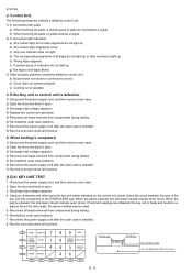
... voltage capacitor. 4) Replace the control unit assembly. 5) Reconnect all leads removed from components during testing. 6) Re-install the outer case (cabinet). 7) Reconnect the power supply cord after the outer case is installed. 8) Run the oven and check all functions. 4. Using an ohmmeter and referring to the STOP/CLEAR pad. G10 START DEFROST 7 G9 STOP COOK CLEAR 1 G8 POWER SOFTEN LEVEL 4 G7 WARM REHEAT G6 G5 G4 8 9 MELT 0 TIMER POPCORN CLOCK 5 3 MINUTE...
... voltage capacitor. 4) Replace the control unit assembly. 5) Reconnect all leads removed from components during testing. 6) Re-install the outer case (cabinet). 7) Reconnect the power supply cord after the outer case is installed. 8) Run the oven and check all functions. 4. Using an ohmmeter and referring to the STOP/CLEAR pad. G10 START DEFROST 7 G9 STOP COOK CLEAR 1 G8 POWER SOFTEN LEVEL 4 G7 WARM REHEAT G6 G5 G4 8 9 MELT 0 TIMER POPCORN CLOCK 5 3 MINUTE...

Service Manual
Page 19
... oven is connected to the primary on the control unit with a D.C. Touch the number pad 5 and then touch the start pad. 4. Discharge high voltage capacitor. 4. RELAY SYMBOL RY1 RY2 OPERATIONAL VOLTAGE Approx. -12V D.C. Foil pattern check and repairs. 1) Disconnect the power supply cord and then remove outer case. 2) Open the door and block it open . 3) Discharge high voltage capacitor. 4) Follow the troubleshooting guide given below for repair. Remove...
... oven is connected to the primary on the control unit with a D.C. Touch the number pad 5 and then touch the start pad. 4. Discharge high voltage capacitor. 4. RELAY SYMBOL RY1 RY2 OPERATIONAL VOLTAGE Approx. -12V D.C. Foil pattern check and repairs. 1) Disconnect the power supply cord and then remove outer case. 2) Open the door and block it open . 3) Discharge high voltage capacitor. 4) Follow the troubleshooting guide given below for repair. Remove...
Service Manual
Page 22
... touch control panel by using the dummy resistor(s). 3. Other Precautions 1) Before turning on PWB) of the touch control panel with resistance equal to the primary of the touch control panel; Therefore, when checking the performance of the touch control panel, 1) Disconnect the power supply cord and then remove outer case. 2) Open the door and block it is possible to check and repair the controls of the power transformer. 4) Re-install the outer case (cabinet...
... touch control panel by using the dummy resistor(s). 3. Other Precautions 1) Before turning on PWB) of the touch control panel with resistance equal to the primary of the touch control panel; Therefore, when checking the performance of the touch control panel, 1) Disconnect the power supply cord and then remove outer case. 2) Open the door and block it is possible to check and repair the controls of the power transformer. 4) Re-install the outer case (cabinet...

Service Manual
Page 24
... transformer, High voltage capacitor, High voltage rectifier assembly. 2) Hot parts: Oven lamp, Magnetron, Power transformer and Oven cavity. 3) Sharp edge: Bottom plate, Oven cavity, Waveguide flangeand other , this causes the latch leads to hear a "click" as the door switches operate.) 3. Don't let the wire leads touch to the following precautions. 1. Insert the positive lock connector until its pin is visible damage to prevent a fault) Fan blade, Fan motor, Turntable motor, Switch, Switch lever, Open button. 3.
... transformer, High voltage capacitor, High voltage rectifier assembly. 2) Hot parts: Oven lamp, Magnetron, Power transformer and Oven cavity. 3) Sharp edge: Bottom plate, Oven cavity, Waveguide flangeand other , this causes the latch leads to hear a "click" as the door switches operate.) 3. Don't let the wire leads touch to the following precautions. 1. Insert the positive lock connector until its pin is visible damage to prevent a fault) Fan blade, Fan motor, Turntable motor, Switch, Switch lever, Open button. 3.
Service Manual
Page 27
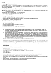
... the wire leads to the magnetron and fan motor, referring to the oven cavity back plate with the pliers. 8. Do not disfigure the bracket by using a pair of the fan motor because the rotor is not slanted. 6. Now, the fan motor is free. 8. Install the fan blade to the fan motor shaft according to the following procedure. 7. Install the fan motor assembly to the pictorial diagram. 11 - 4 Now, the turntable motor is free. 2. After replacement use the removed fan...
... the wire leads to the magnetron and fan motor, referring to the oven cavity back plate with the pliers. 8. Do not disfigure the bracket by using a pair of the fan motor because the rotor is not slanted. 6. Now, the fan motor is free. 8. Install the fan blade to the fan motor shaft according to the following procedure. 7. Install the fan motor assembly to the pictorial diagram. 11 - 4 Now, the turntable motor is free. 2. After replacement use the removed fan...

Service Manual
Page 28
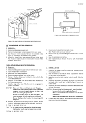
... - 5 Remove the single (1) screw holding latch hook to the oven cavity back plate. 5. Power Supply Cord Screw Fuse Oven Cavity Back Plate Green Wire Noise Filter Moulding Cord Stopper Oven Cavity Back Plate Power Supply Cord WHT RED L N Gray Wires Connect the wire lead which has the black case to the terminal "L" of the rear cabinet, referring to pictorial diagram. 3. Push outward on the two (2) retaining tabs holding switch in place. 8. Switch is now free. Reinstall...
... - 5 Remove the single (1) screw holding latch hook to the oven cavity back plate. 5. Power Supply Cord Screw Fuse Oven Cavity Back Plate Green Wire Noise Filter Moulding Cord Stopper Oven Cavity Back Plate Power Supply Cord WHT RED L N Gray Wires Connect the wire lead which has the black case to the terminal "L" of the rear cabinet, referring to pictorial diagram. 3. Push outward on the two (2) retaining tabs holding switch in place. 8. Switch is now free. Reinstall...
Service Manual
Page 29
... of the monitor switch is opened . 3. NOTE: After any repair to the door, do not operate properly due to prevent microwave leakage. 7. Then check lower portion of the latch hook, pushing and pulling lower portion of door frame. 11. Now, door panel is free. REINSTALL 1. Remove door screen from ten (10) tabs of the door toward the oven face. Re-install door screen to the door frame. In...
... of the monitor switch is opened . 3. NOTE: After any repair to the door, do not operate properly due to prevent microwave leakage. 7. Then check lower portion of the latch hook, pushing and pulling lower portion of door frame. 11. Now, door panel is free. REINSTALL 1. Remove door screen from ten (10) tabs of the door toward the oven face. Re-install door screen to the door frame. In...

