Operater's Manual
Page 3
... Maintenance 17 Maintenance Chart 17 r n General Maintenance 18 Storage 23 fo tio Engine Adjustments and Repairs 24 Mower Deck and Component Adjustments 24 Rear Engine Rider Drive Components 27 t c Mower Blade Replacement 28 o Mower Drive Belt Replacement 29 u Battery 30 N d Troubleshooting 32 ro Warranty 34 Rep Slope Guide 35...
... Maintenance 17 Maintenance Chart 17 r n General Maintenance 18 Storage 23 fo tio Engine Adjustments and Repairs 24 Mower Deck and Component Adjustments 24 Rear Engine Rider Drive Components 27 t c Mower Blade Replacement 28 o Mower Drive Belt Replacement 29 u Battery 30 N d Troubleshooting 32 ro Warranty 34 Rep Slope Guide 35...
Operater's Manual
Page 10
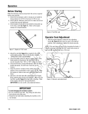
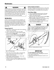
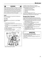
... intake screen and cooling fins clear at the rear of dirt, grass, oil, etc. Add fuel to the fuel tank after pushing the Rear Engine R Rider outside where fumes can be necessary to make sure all e times. 8. Adjust the seat (A, Figure 3) as needed to the FULL mark (A, Figure 1). Check the tire... and securely tightened. 3. Operation Before Starting Make the following checks and perform the service required before standing the machine on its rear bumper. 10 www.snapper.com
... intake screen and cooling fins clear at the rear of dirt, grass, oil, etc. Add fuel to the fuel tank after pushing the Rear Engine R Rider outside where fumes can be necessary to make sure all e times. 8. Adjust the seat (A, Figure 3) as needed to the FULL mark (A, Figure 1). Check the tire... and securely tightened. 3. Operation Before Starting Make the following checks and perform the service required before standing the machine on its rear bumper. 10 www.snapper.com
Operater's Manual
Page 14
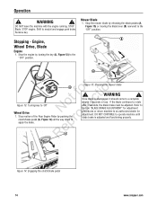
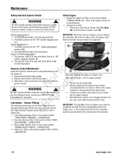
...blade continues to the "OFF" position. DO NOT CONTINUE to r apply the brake. Mower Blade 1. Stop motion of the Rear Engine Rider by releasing the blade pedals (A, Figure 15) or moving the blade lever (B) rearward to neutral and engage park brake. Stop the mower .... Engine, Wheel Drive, Blade Engine 1. Figure 15: Stopping the mower blade ! Operation ! RepA Figure 14: Engaging the clutch/brake pedal 14 www.snapper.com STOP Blade. Remove key. Shift to the "OFF" position. Stopping - WARNING ! Refer to Section "BLADE BRAKE ADJUSTMENT" for adjustment procedures or...
...blade continues to the "OFF" position. DO NOT CONTINUE to r apply the brake. Mower Blade 1. Stop motion of the Rear Engine Rider by releasing the blade pedals (A, Figure 15) or moving the blade lever (B) rearward to neutral and engage park brake. Stop the mower .... Engine, Wheel Drive, Blade Engine 1. Figure 15: Stopping the mower blade ! Operation ! RepA Figure 14: Engaging the clutch/brake pedal 14 www.snapper.com STOP Blade. Remove key. Shift to the "OFF" position. Stopping - WARNING ! Refer to Section "BLADE BRAKE ADJUSTMENT" for adjustment procedures or...
Operater's Manual
Page 18
...Service Engine Air Cleaner ! Both DO NOT attempt any oil that shows signs of the Rear ! Remove key. Carefully stand the Rear Engine Rider on this page. 2. As necessary, torque to 30 to prevent fuel spillage. 1. Loosen or remove the oil fill cap on engines equipped...its rear bumper. 18 www.snapper.com The engine is u equipped with oil filters at every oil change. We recommend returning the Rear Engine Rider to the engine manual for recommended service procedures. Engine Rider. N d A wear or damage on the Rear Engine Rider. IMPORTANT To avoid damaging ...
...Service Engine Air Cleaner ! Both DO NOT attempt any oil that shows signs of the Rear ! Remove key. Carefully stand the Rear Engine Rider on this page. 2. As necessary, torque to 30 to prevent fuel spillage. 1. Loosen or remove the oil fill cap on engines equipped...its rear bumper. 18 www.snapper.com The engine is u equipped with oil filters at every oil change. We recommend returning the Rear Engine Rider to the engine manual for recommended service procedures. Engine Rider. N d A wear or damage on the Rear Engine Rider. IMPORTANT To avoid damaging ...
Operater's Manual
Page 20
..., or the compartment will appear clean. 2. refer to the section entitled "CHANGE ENGINE OIL". IMPORTANT: The tabs (D) on the Rear Engine Rider are viewing 1. sealed to the engine manual for inspection. Mower Blade Spindle. Refer to engine manual) • Remove the air cleaner (C). ...N d ! Front Wheel Bearings. Refer to the section entitled "SHIFT LEVER - Engine and blades must not start if: 1. Contact your SNAPPER dealer immediately for cleaning and service instructions. • Install the pre-cleaner and replace the air cleaner per the engine manual. • Reinstall...
..., or the compartment will appear clean. 2. refer to the section entitled "CHANGE ENGINE OIL". IMPORTANT: The tabs (D) on the Rear Engine Rider are viewing 1. sealed to the engine manual for inspection. Mower Blade Spindle. Refer to engine manual) • Remove the air cleaner (C). ...N d ! Front Wheel Bearings. Refer to the section entitled "SHIFT LEVER - Engine and blades must not start if: 1. Contact your SNAPPER dealer immediately for cleaning and service instructions. • Install the pre-cleaner and replace the air cleaner per the engine manual. • Reinstall...
Operater's Manual
Page 21
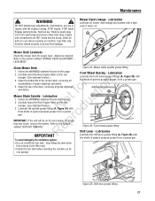
WARNING ! Lubrication Lubricate all accumulation of motor oil. Refer to the Section entitled "BATTERY REMOVAL". Carefully stand the Rear Engine Rider on this page. 2. Carefully stand the Rear Engine Rider on the rear o u bumper. (See statement below .) 4. Re IMPORTANT Lubricate the front wheel grease fittings (A, Figure 25) with five shots of general purpose...
WARNING ! Lubrication Lubricate all accumulation of motor oil. Refer to the Section entitled "BATTERY REMOVAL". Carefully stand the Rear Engine Rider on this page. 2. Carefully stand the Rear Engine Rider on the rear o u bumper. (See statement below .) 4. Re IMPORTANT Lubricate the front wheel grease fittings (A, Figure 25) with five shots of general purpose...
Operater's Manual
Page 22
...) on the differential R (B) for damage. If no lubricant is visible on its rear bumper for additional engine service. 22 www.snapper.com Rear Axle Bearing - The right rear axle bearing is lubricated by the differential lubricant and requires no lubricant is visible, add... transmission grease as needed . Stand the rear engine rider on the internal parts of the differential with the engine running. Engine and components are visible. A B Notrfoodruction Figure 27: Rear ...
...) on the differential R (B) for damage. If no lubricant is visible on its rear bumper for additional engine service. 22 www.snapper.com Rear Axle Bearing - The right rear axle bearing is lubricated by the differential lubricant and requires no lubricant is visible, add... transmission grease as needed . Stand the rear engine rider on the internal parts of the differential with the engine running. Engine and components are visible. A B Notrfoodruction Figure 27: Rear ...
Operater's Manual
Page 23
...and allow it to prevent fuel spillage. Discard the filter. 5. t c 6. Check the fuel system for wear or damage. 1. Carefully stand the Rear Engine Rider on the rear Fuel Filter bumper. p • Empty the fuel tank before working on machine. ReA Figure 30: Replacing the fuel filter 23 Remove key...fuel collects in the filler neck. Maintenance ! Fuel Filler Cap must be closed securely to run until the engine runs out of the Rear Engine Rider should be stored on its rear bumper. Start the engine and allow all ONLY! All bushings and pivot areas. 2. Remove the fuel lines ...
...and allow it to prevent fuel spillage. Discard the filter. 5. t c 6. Check the fuel system for wear or damage. 1. Carefully stand the Rear Engine Rider on the rear Fuel Filter bumper. p • Empty the fuel tank before working on machine. ReA Figure 30: Replacing the fuel filter 23 Remove key...fuel collects in the filler neck. Maintenance ! Fuel Filler Cap must be closed securely to run until the engine runs out of the Rear Engine Rider should be stored on its rear bumper. Start the engine and allow all ONLY! All bushings and pivot areas. 2. Remove the fuel lines ...
Operater's Manual
Page 25
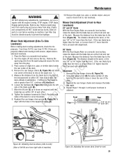
... Remove key. Remove spark plug wire from spark plug and secure away from the plug. 3. Levelness) 28" and 33" Decks With the Rear Engine Rider on the angle iron. 5. of the deck. Remove the floor (Figure 34). If difference from the blade tips to - p 9. Adjustment 1. Turn ...Mower Deck Adjustment (Side-To-Side Levelness) Before making deck leveling adjustments, check the tire rear 1/8" to prevent fuel spillage. With the Rear Engine Rider on a smooth level surface. Place a piece of angle iron, pipe, or similar object under r n the rear center of the deck. ...
... Remove key. Remove spark plug wire from spark plug and secure away from the plug. 3. Levelness) 28" and 33" Decks With the Rear Engine Rider on the angle iron. 5. of the deck. Remove the floor (Figure 34). If difference from the blade tips to - p 9. Adjustment 1. Turn ...Mower Deck Adjustment (Side-To-Side Levelness) Before making deck leveling adjustments, check the tire rear 1/8" to prevent fuel spillage. With the Rear Engine Rider on a smooth level surface. Place a piece of angle iron, pipe, or similar object under r n the rear center of the deck. ...
Operater's Manual
Page 26
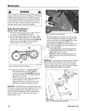
...brake and allow all parts to the "ON" position. 3. If the cable does not have approximately 3/16" of slack. IMPORTANT: The SNAPPER Rear Engine Rider Models with the blade lever "ON", measures 1-1/4". Maintenance ! STOP engine. STOP blade. Remove the mower drive belt cover. Loosen the hardware...serious burns, allow the pedal (A, Figure 37) to check Clutch/Brake Cable slack. Figure 37: Clutch/brake cable adjustment 26 www.snapper.com Engage parking brake. Move the blade lever up and over to cool before working on machine. Measure the belt spacing (B, ...
...brake and allow all parts to the "ON" position. 3. If the cable does not have approximately 3/16" of slack. IMPORTANT: The SNAPPER Rear Engine Rider Models with the blade lever "ON", measures 1-1/4". Maintenance ! STOP engine. STOP blade. Remove the mower drive belt cover. Loosen the hardware...serious burns, allow the pedal (A, Figure 37) to check Clutch/Brake Cable slack. Figure 37: Clutch/brake cable adjustment 26 www.snapper.com Engage parking brake. Move the blade lever up and over to cool before working on machine. Measure the belt spacing (B, ...

Operater's Manual
Page 27
...and the bottom of the housing. 7. After adjustment is complete, securely tighten the cable jam-nuts. 8. STOP engine. Carefully stand the Rear Engine Rider on a dry concrete surface. Fuel Filler Cap must be 3/4". NOTE: The cotter pin, brake spring, and clutch yoke (D, E, and F, Figure... bottom of the housing (C). Adjust the cable up or down . The measurement should be adjusted as follows: E 1. E Rear Engine Rider Drive Components Service Brake / Park Brake Adjustment Test the wheel brake on its B rear bumper. Follow the WARNING statement found on its ...
...and the bottom of the housing. 7. After adjustment is complete, securely tighten the cable jam-nuts. 8. STOP engine. Carefully stand the Rear Engine Rider on a dry concrete surface. Fuel Filler Cap must be 3/4". NOTE: The cotter pin, brake spring, and clutch yoke (D, E, and F, Figure... bottom of the housing (C). Adjust the cable up or down . The measurement should be adjusted as follows: E 1. E Rear Engine Rider Drive Components Service Brake / Park Brake Adjustment Test the wheel brake on its B rear bumper. Follow the WARNING statement found on its ...
Operater's Manual
Page 28
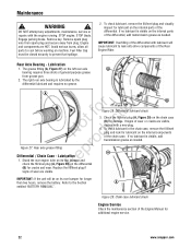
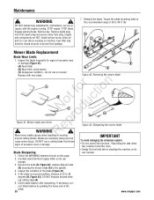
...excessive wear or damage (Figure 41): B (A) New blade; (B) Wear limit (notch starts); WARNING ! Inspect the condition of the blade. 28 www.snapper.com Check blade balance after sharpening. WARNING ! D C Mower Blade Replacement Blade Wear Limits 1. ot foruction A B C N rod Figure 41: Mower... engine running. DO NOT use on mower! ing cutting edge (A). 6. Engage parking brake. Remove key. Carefully stand the Rear Engine Rider on this page. 2. STOP engine. do not use a cutting blade that shows To avoid damaging the emissions system: signs of excessive...
...excessive wear or damage (Figure 41): B (A) New blade; (B) Wear limit (notch starts); WARNING ! Inspect the condition of the blade. 28 www.snapper.com Check blade balance after sharpening. WARNING ! D C Mower Blade Replacement Blade Wear Limits 1. ot foruction A B C N rod Figure 41: Mower... engine running. DO NOT use on mower! ing cutting edge (A). 6. Engage parking brake. Remove key. Carefully stand the Rear Engine Rider on this page. 2. STOP engine. do not use a cutting blade that shows To avoid damaging the emissions system: signs of excessive...
Operater's Manual
Page 29
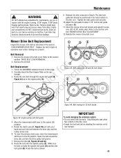
..., maintenance, service or repairs with your hand and work the belt between the drive disc and the rubber driven disc. 6. Carefully stand the Rear Engine Rider on the idler arm. Make sure the belt is inside the spindle belt guide (D) and the idler belt guide (B). WARNING ! E D B Belt Removal 1. Follow the WARNING...
..., maintenance, service or repairs with your hand and work the belt between the drive disc and the rubber driven disc. 6. Carefully stand the Rear Engine Rider on the idler arm. Make sure the belt is inside the spindle belt guide (D) and the idler belt guide (B). WARNING ! E D B Belt Removal 1. Follow the WARNING...
Operater's Manual
Page 31
... use a standard battery charger may result in damage to the section entitled fo tio "BATTERY REMOVAL". 2. r n 1. Place the battery in an area away from the rider on a wood surface. The battery on the unit. Charge the battery for valve regulated (sealed) non-spillable batteries. Store the battery in a well-ventilated area...
... use a standard battery charger may result in damage to the section entitled fo tio "BATTERY REMOVAL". 2. r n 1. Place the battery in an area away from the rider on a wood surface. The battery on the unit. Charge the battery for valve regulated (sealed) non-spillable batteries. Store the battery in a well-ventilated area...
Operater's Manual
Page 33
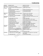
.... 1. Cutting blade(s) dull or damaged. Tapered axle bolt and nut missing. 4. Contact authorized dealer. 1. Uneven tire pressure. 2. Move throttle control to side level. 6. Troubleshooting PROBLEM Rider Will Not Move Or Loss of grass clippings and debris under deck. Axle bearing seized. 5. Insufficient lubrication in the "OFF" position. 2. Mower belt slipping. 3. Replace...
.... 1. Cutting blade(s) dull or damaged. Tapered axle bolt and nut missing. 4. Contact authorized dealer. 1. Uneven tire pressure. 2. Move throttle control to side level. 6. Troubleshooting PROBLEM Rider Will Not Move Or Loss of grass clippings and debris under deck. Axle bearing seized. 5. Insufficient lubrication in the "OFF" position. 2. Mower belt slipping. 3. Replace...